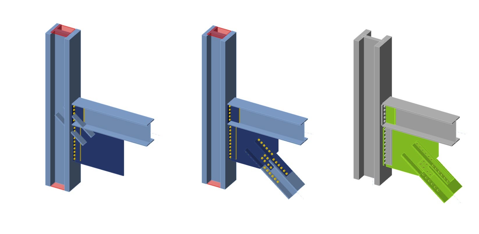
Claw angle on WF bracing connection (AISC)
1 Open project
Claw angle connection file
To begin, download and open the attached IDEA StatiCa file above. The model has been started for this tutorial, the main members and gusset plate have been connected to each other, except for the WF brace. The material properties and bolt type have been selected in advance.

Since this project follows the AISC code, let's ensure that imperial units are set in the model (see How to change the system of units).
2 Design
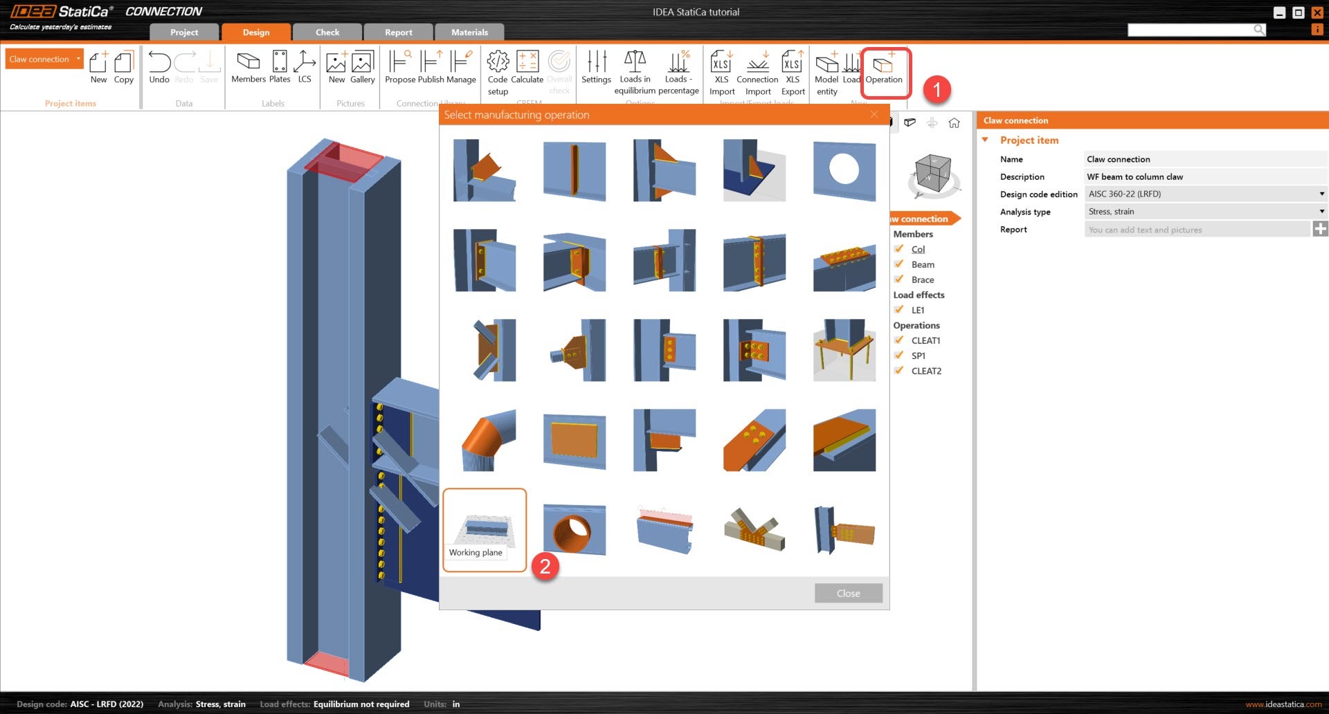
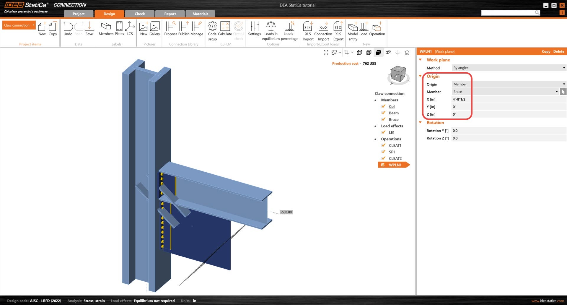
First thing to edit in this model is to extend the bracing system by its x-axis. In order to do so, start by adding the working plane operation. This working plane with be defined in reference to the local coordinate system of the Brace member. See below for the details of the operation.
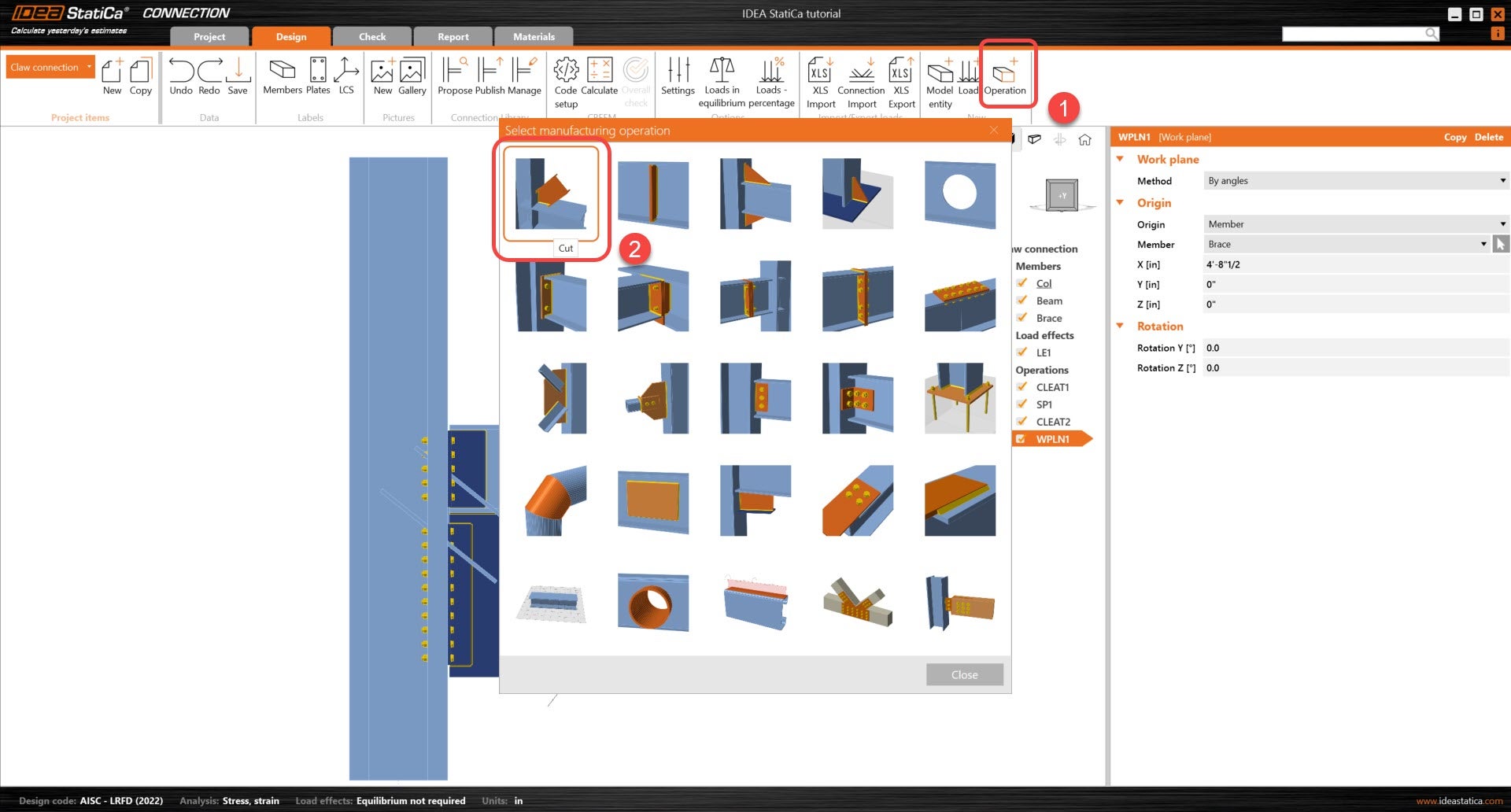
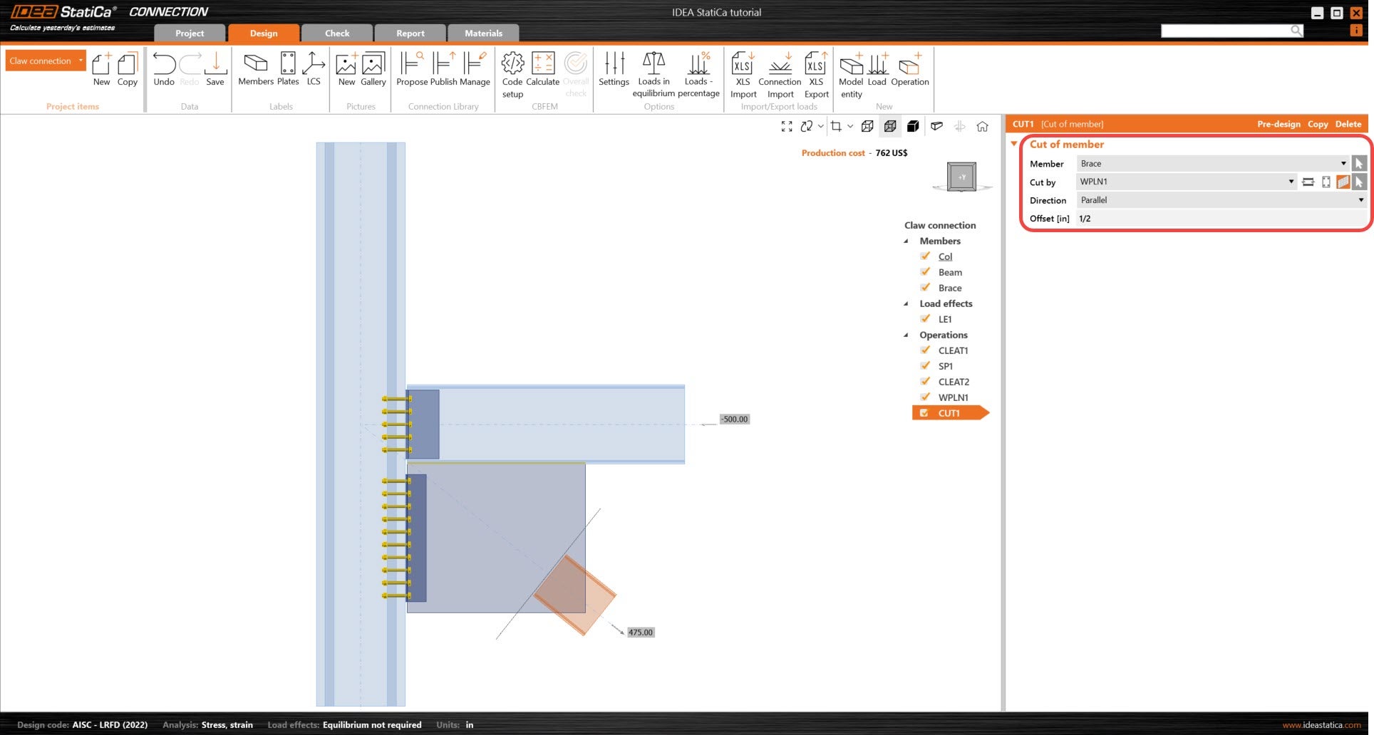
Using the Cut of member operation, the Brace member will be cut by the working plane allowing the member to be offset at the required length from the working point. A Cut of member operation will only cut members and stiffening members only.
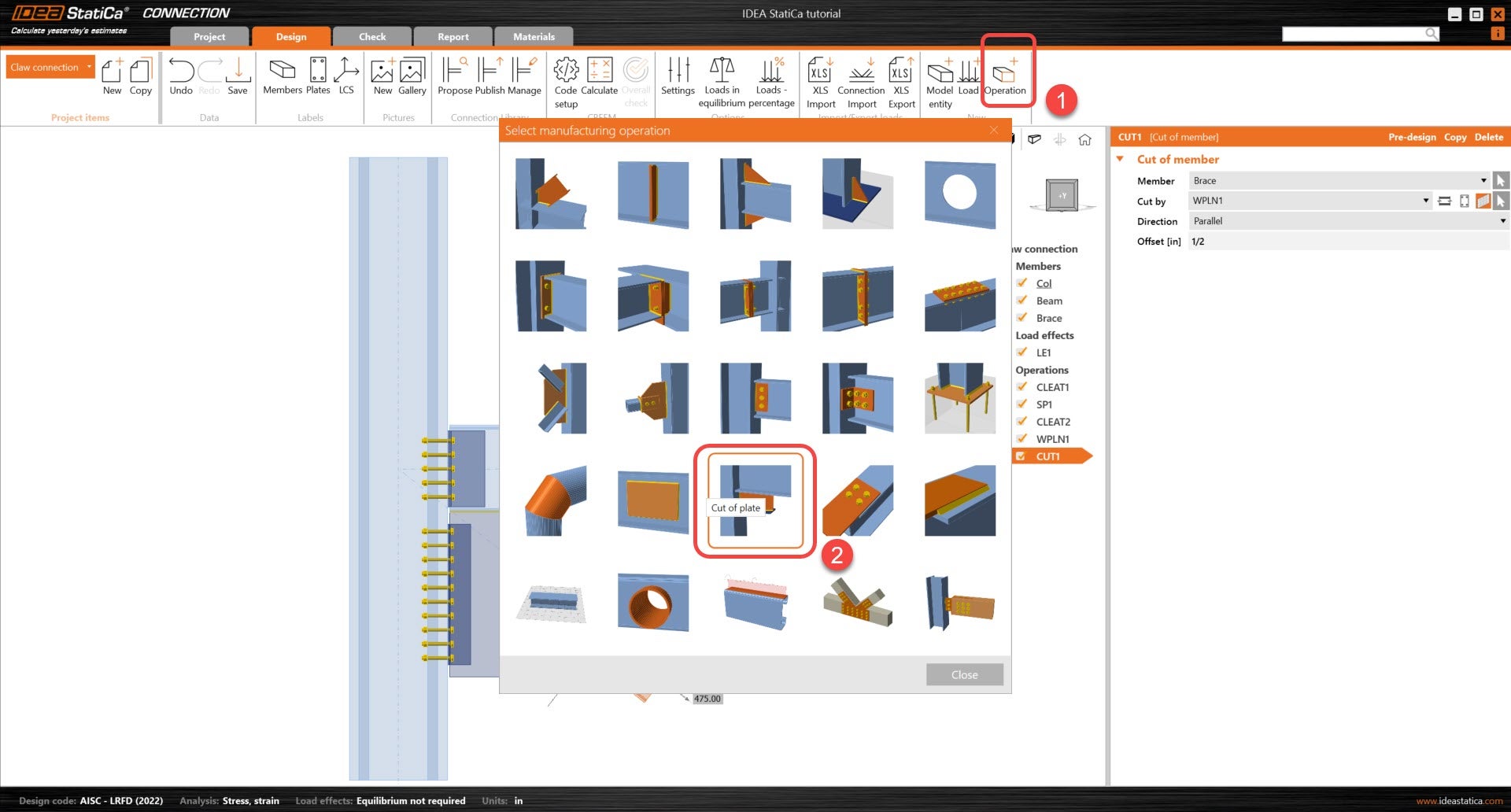
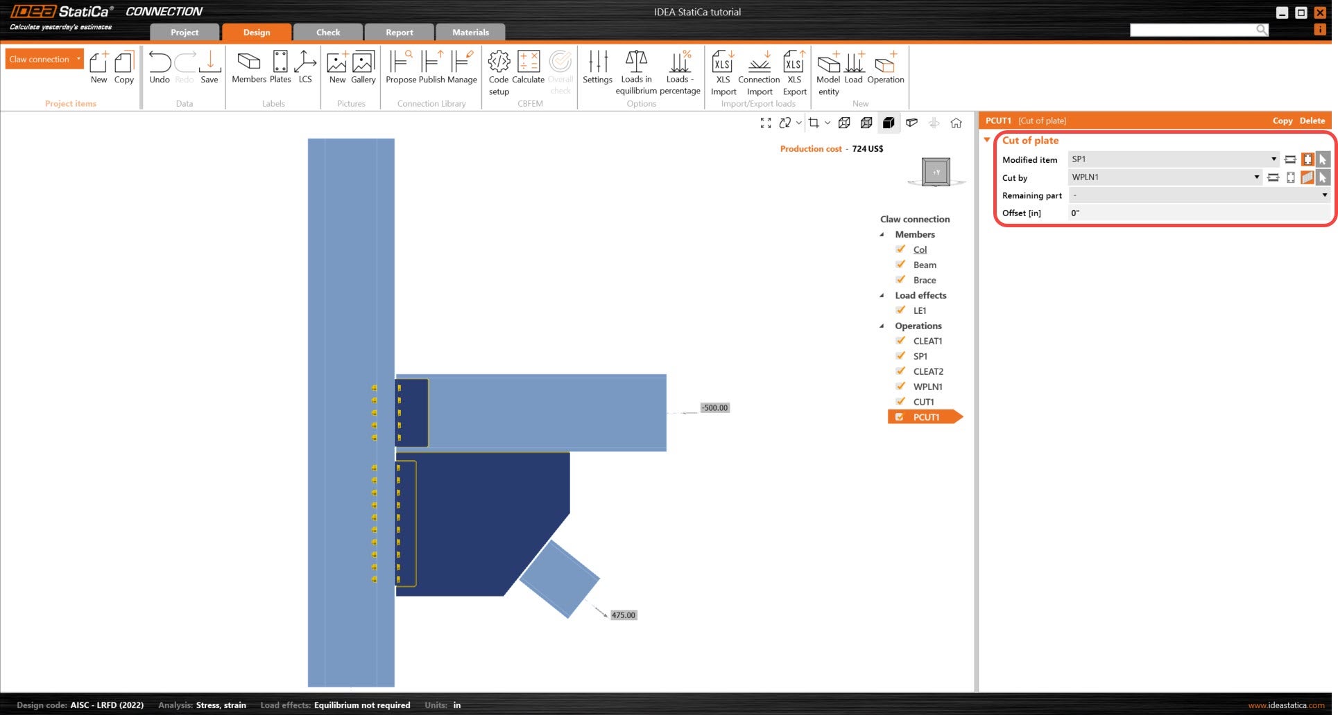
Adding a Cut of plate will help take advantage of the working plane operation so that the intersecting corner of the plate SP1 can be cut on the same plane. This will ensure that the plate's new angled cut is parallel with the Brace member. A Cut of plate operation will cut all plates and plates that take part in a member or stiffening member. Only one plate can be cut per operation.
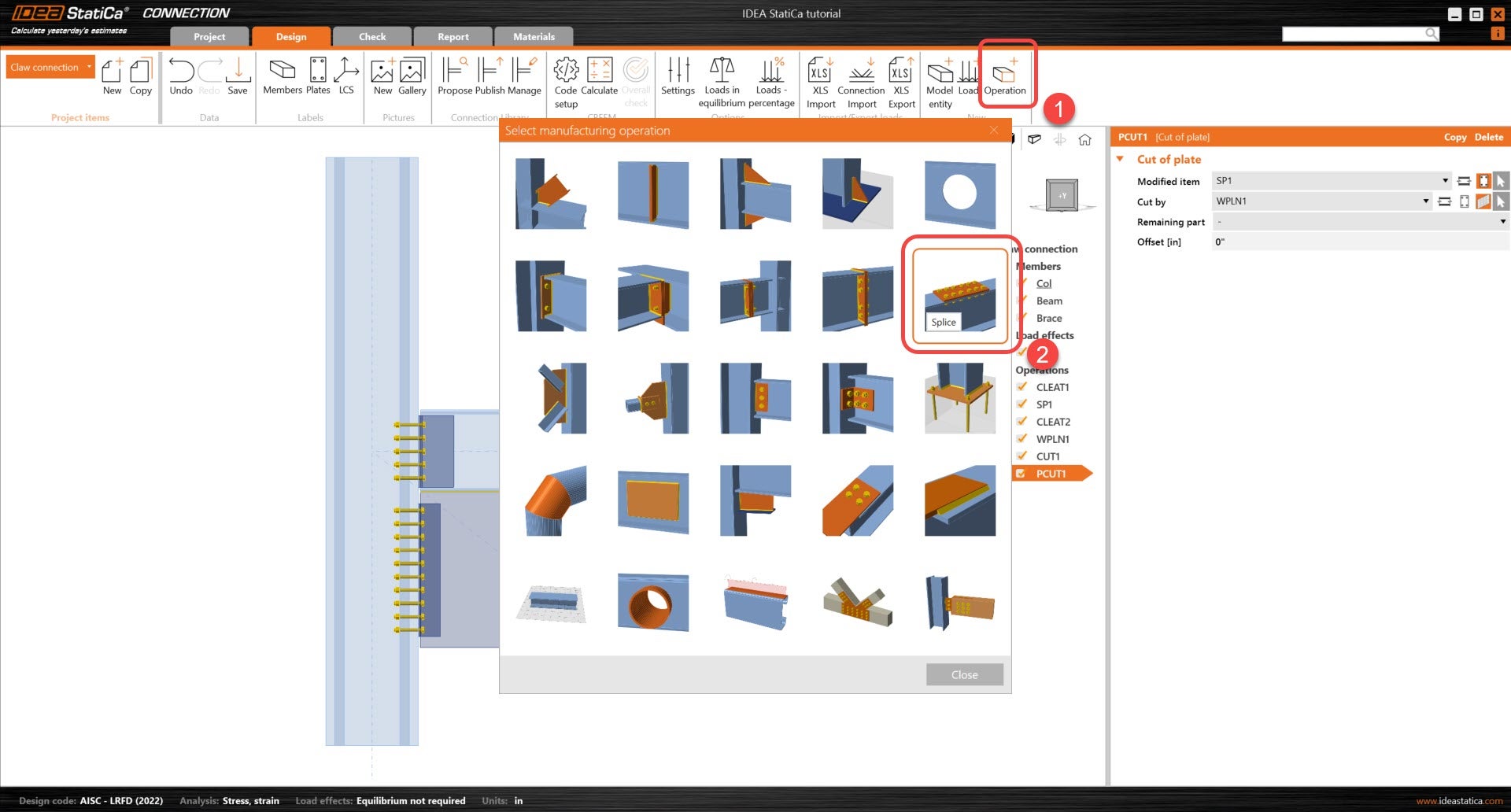
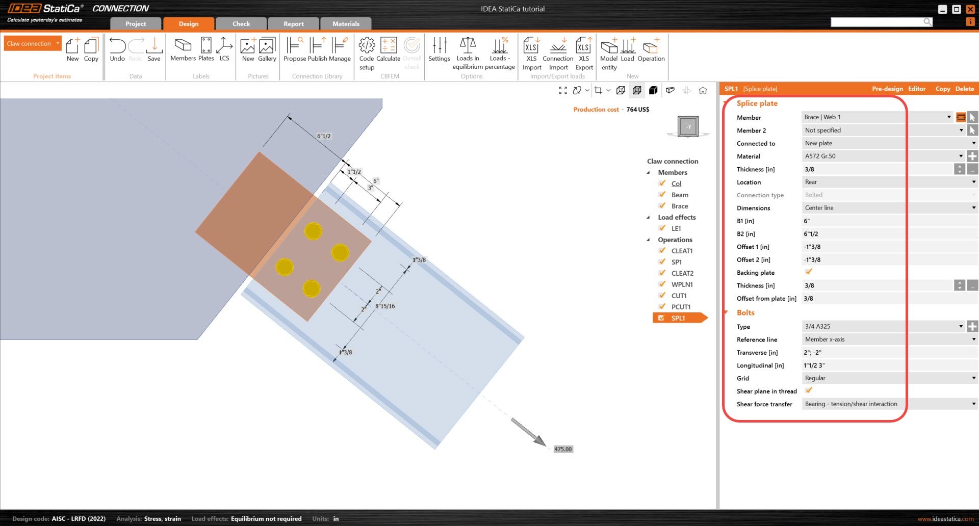
Now, we will focus on the claw connection. To start, lets add a Splice operation to connect the Brace Web to the stiffening plate, SP1. The Splice operation allows for the editing of the plate and bolt placement onto the Brace member. In the bolts section and in other bolt operations, the bolt position can be defined in three different ways.
Absolute delimiter ";" (a semi-colon) - distance measured from the outline of the cross-section (reference line)
Relative delimiter " " (space) - distance measured from the previous bolt row/column.
asterisk " * " - number of bolts placed at equal distances from each other.
E.g., the input of "40; 80; 120; 160; 200" is equal to "40 40 40 40 40" and also "4*40". You can also combine all delimiters, e.g., input "40; 80; 120 40 40".
See the details below for the Splice operation.
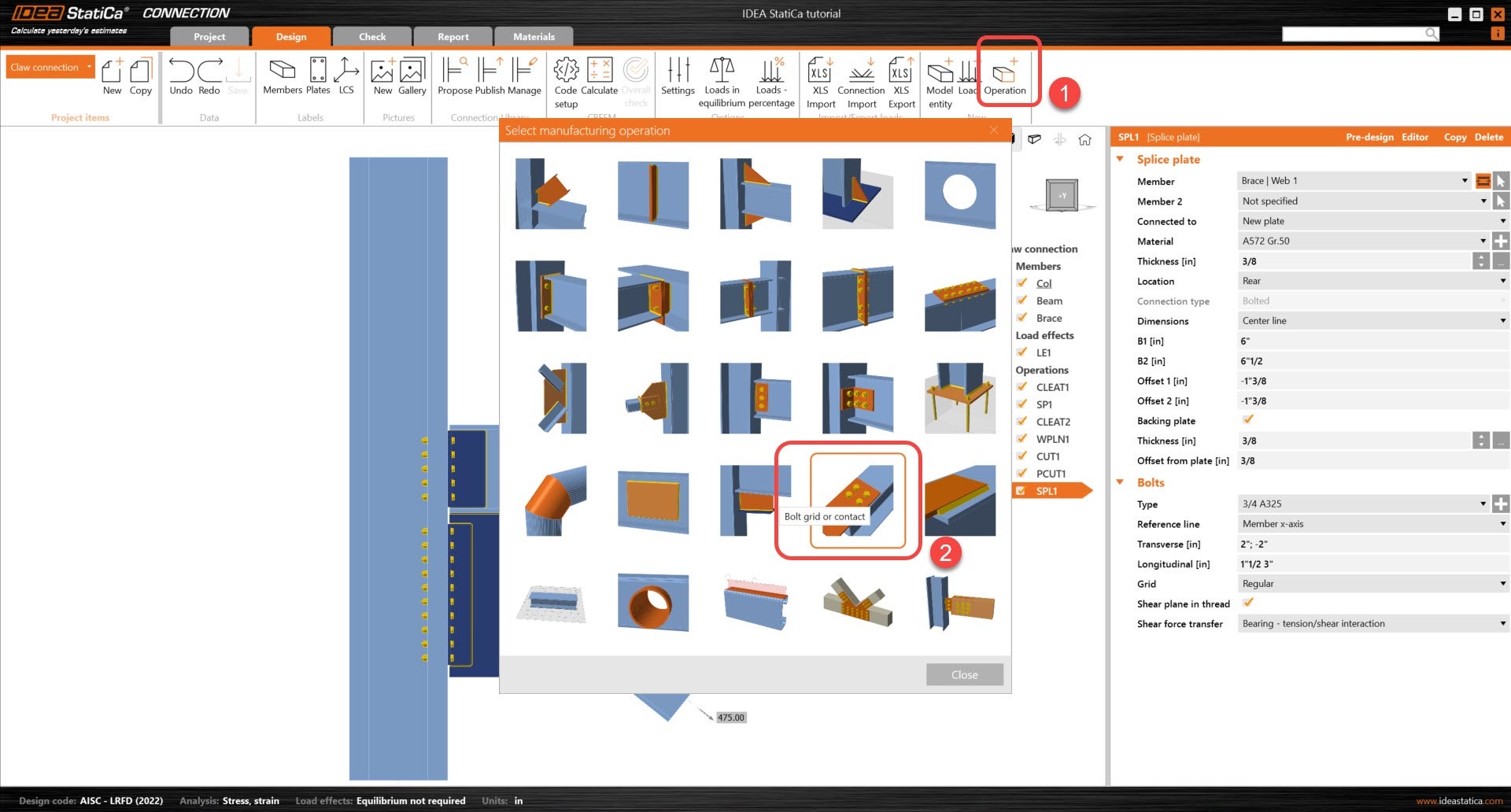
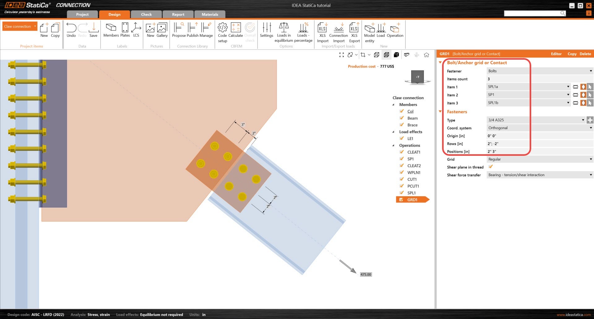
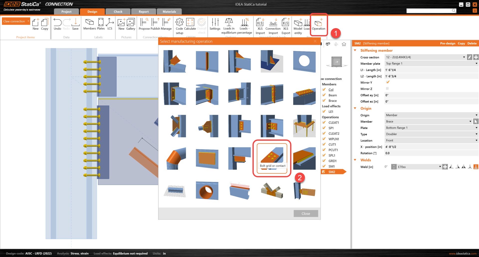
The bolts connecting the Splice plates and stiffening plate, SP1, will need to be added through the Bolt grid or contact operation. The first plate item selected will be used as reference to the position of the bolts.
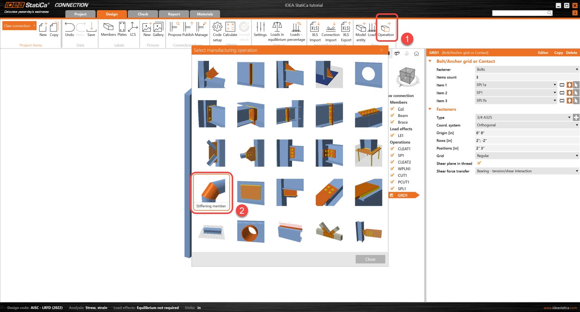
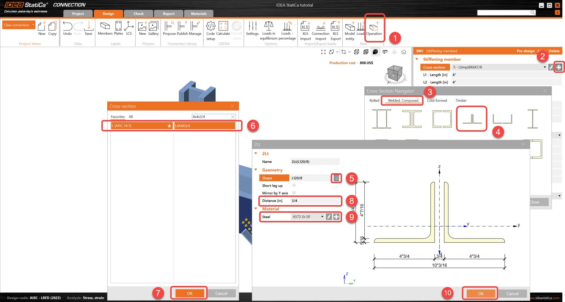
Next, angle sections will be added to connect the top & bottom flange to the stiffening plate, SP1. Since the sections will be used as part of the connection, they can be added through the Stiffening member operation.
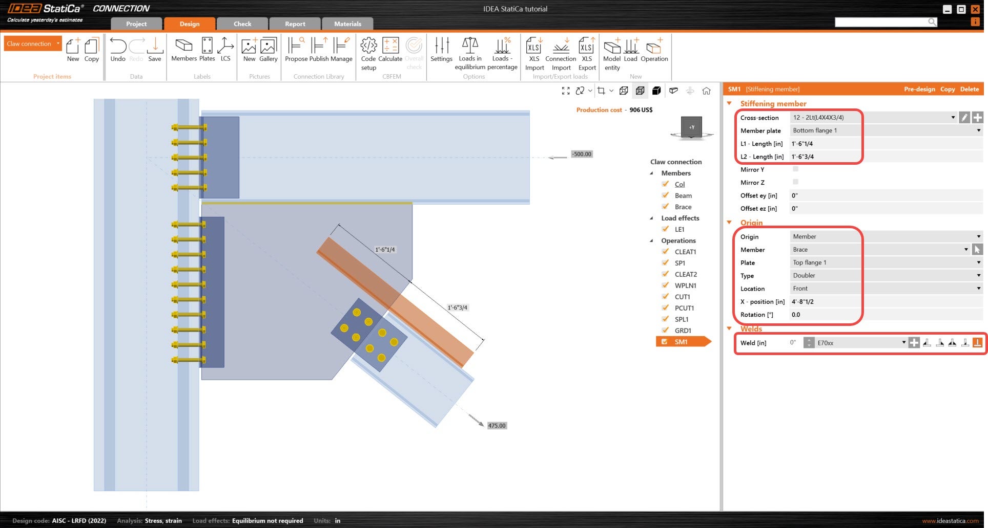
Add a Stiffening member operation and adjust the cross-section type. This stiffening member will be placed on the top flange of the Brace member.
Right click on the operation SM1, and select copy.
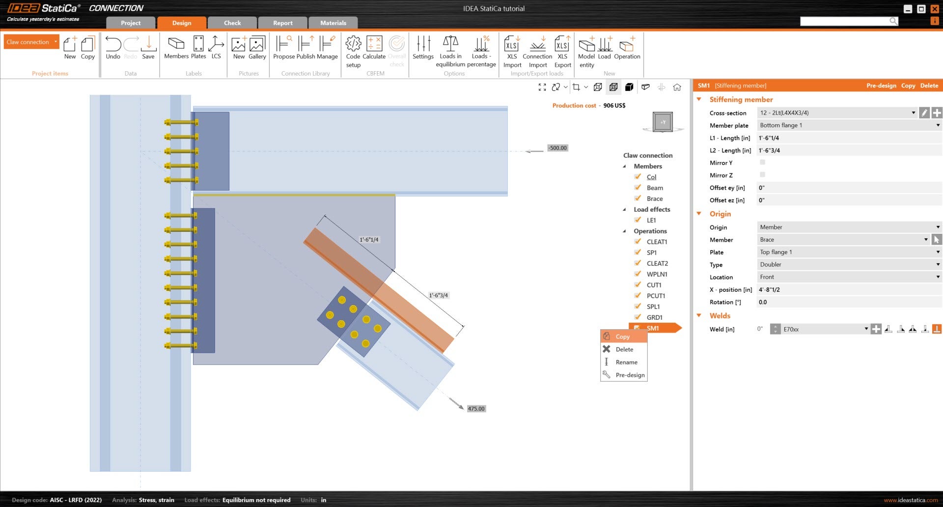
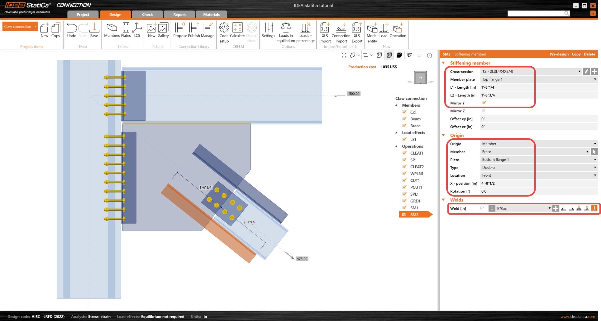
Adjust the following parameters of the new stiffening member so that it is referencing the Brace bottom flange.
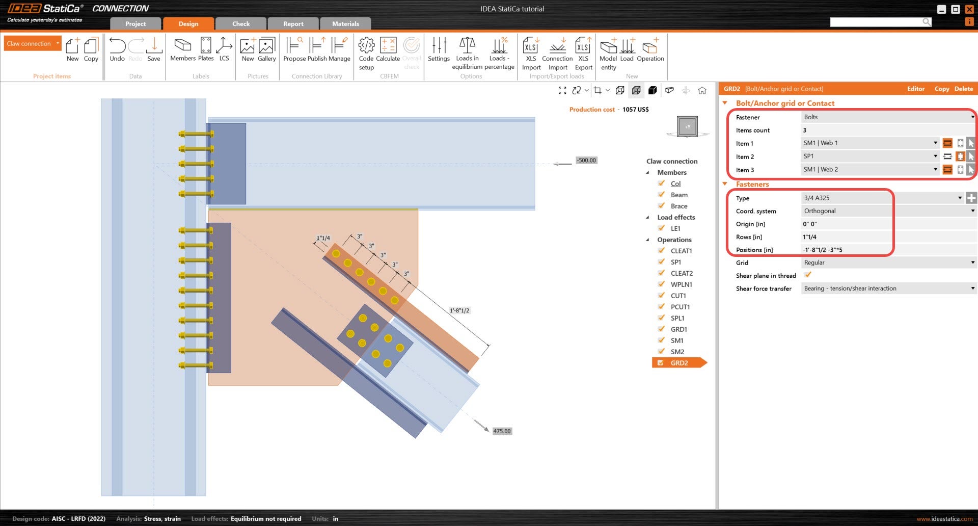
Bolts are now needed to connect the stiffening members. Begin by adding a new Bolt operation and adjust the following parameters so that it connects SM1 and SP1.
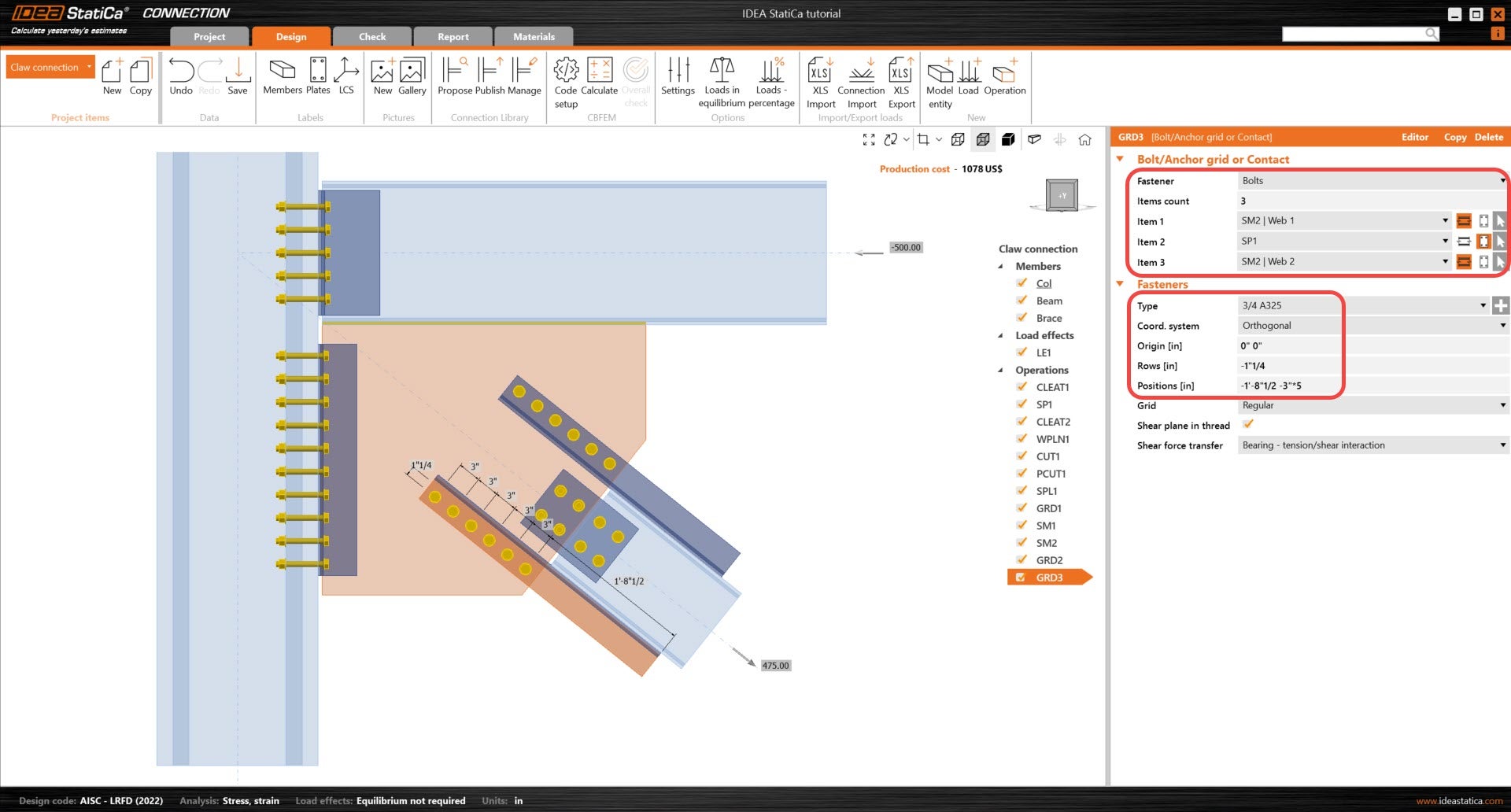
Copy the operation GRD2 and adjust the following parameters of GRD3 so that it connects SM2 and SP1. You will notice that there are very few parameters to adjust in the copied operation.
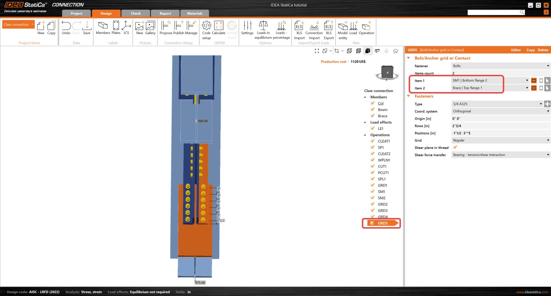
Add a new Grid operation and adjust the following parameters so that it is referencing SM1 and the Brace top flange.
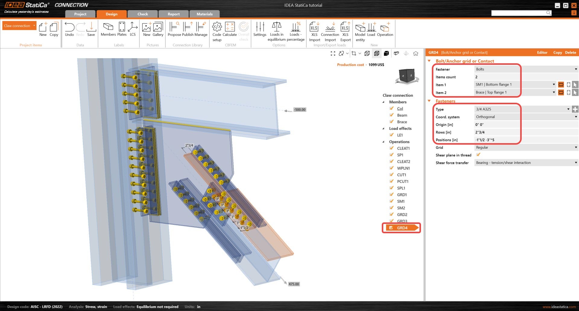
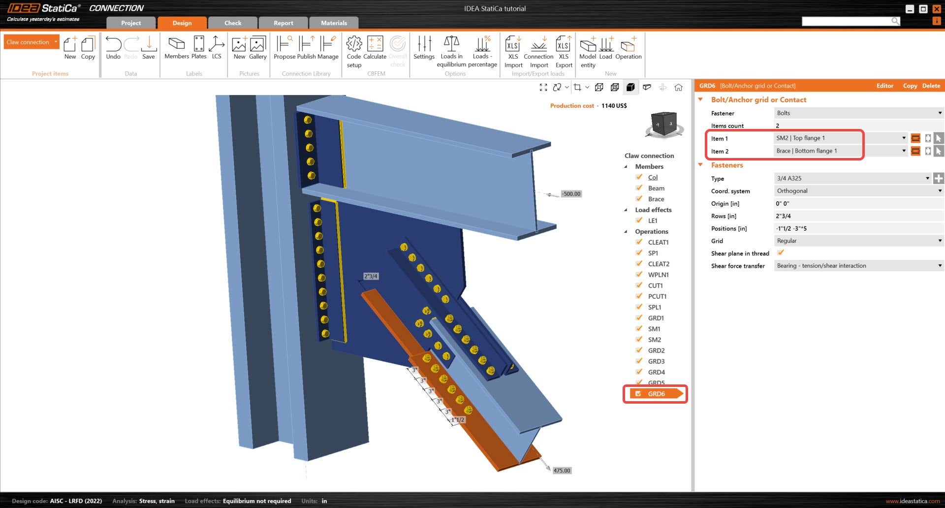
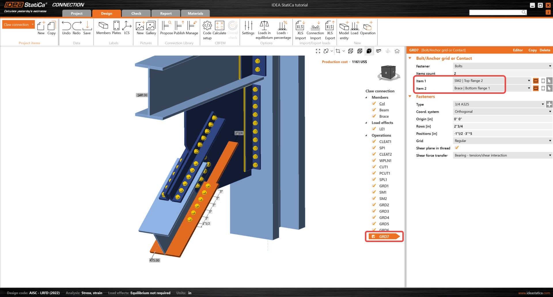
Copy the previous Grid operation three times and adjust the following parameters to finalize the connection model.
3 Calculation and Check
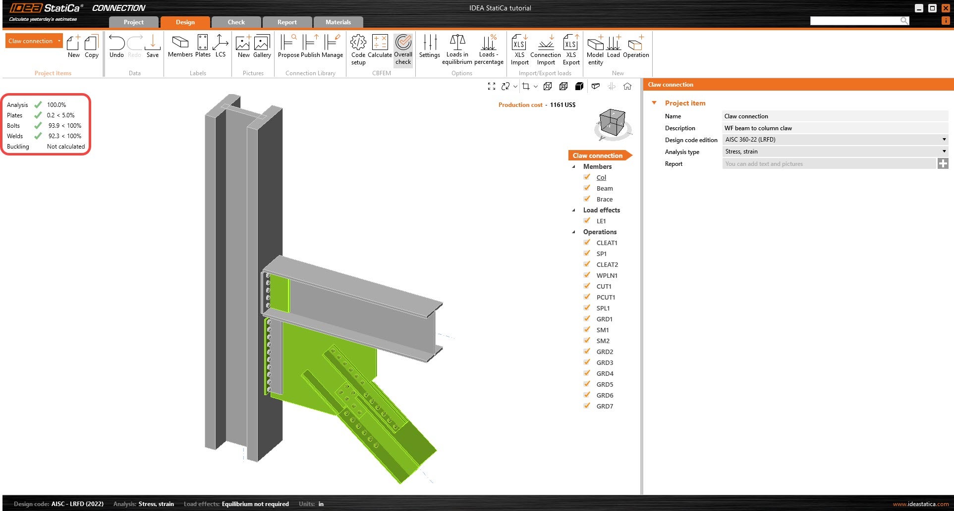
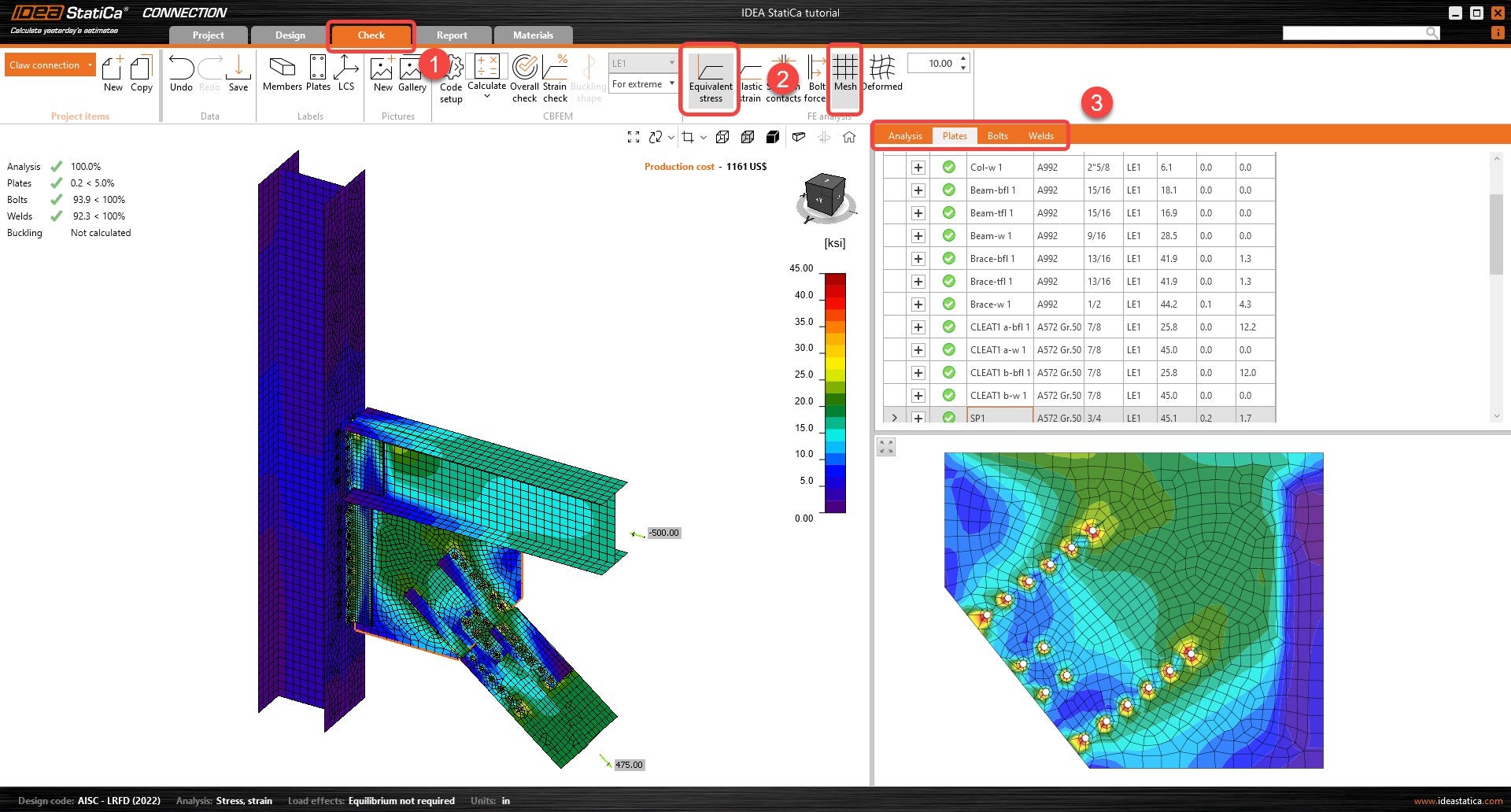
Start the analysis by clicking Calculate in the ribbon. The calculation based on CBFEM is performed, and the Overall check is displayed together with the fundamental values of check results.
Go to the Check tab and activate Equivalent stress and Mesh from the ribbon to observe the stress flow in the connection. The different results for all components (Plates, bolts & welds) are displayed on the right.
4 Report
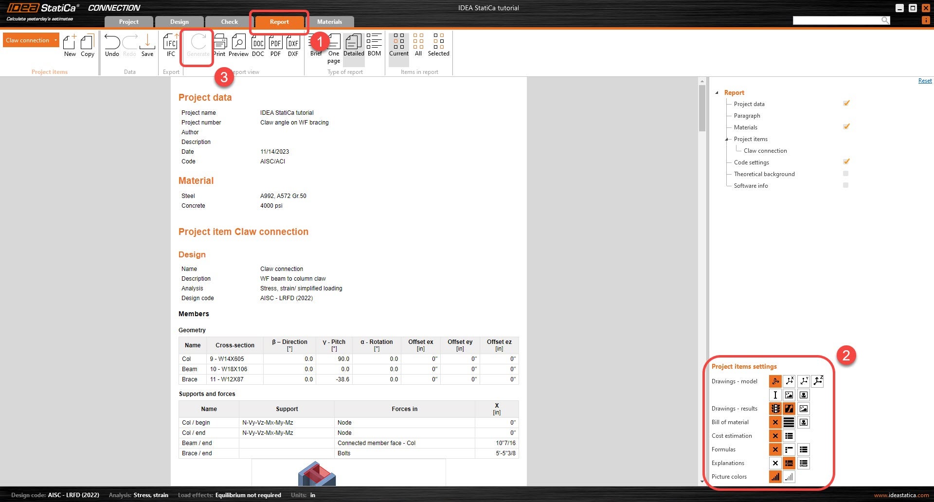
At last, go to the tab Report. IDEA StatiCa offers a fully customizable report where you can add or remove as much detail as needed. Once done, click Generate and the report will be generated with the parameters it was given.
You have modeled, designed, and code-checked a structural steel joint according to AISC.