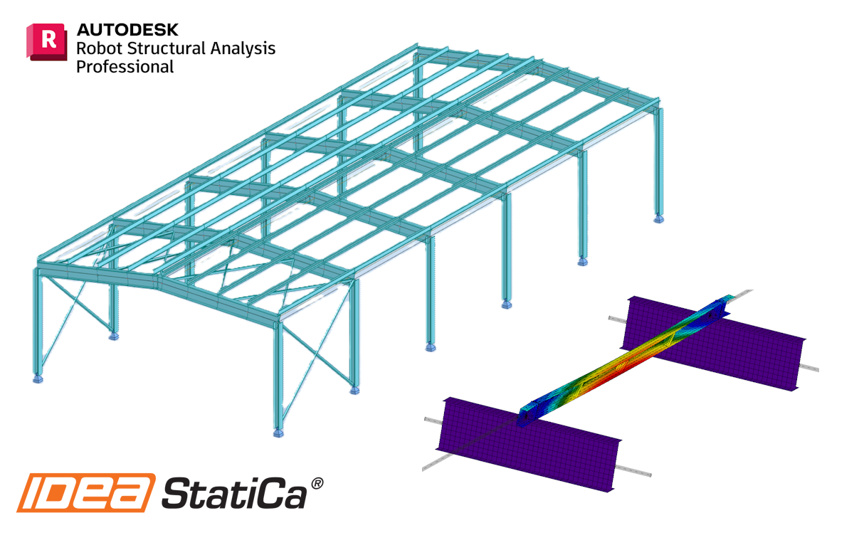
Lien BIM Robot Structural Analysis pour le calcul des éléments acier (EN)
Comment activer le lien
- Téléchargez et installez la dernière version de IDEA StatiCa
- Vérifiez que vous utilisez une version autorisée de votre solution MEF/BIM
IDEA StatiCa intègre les liens BIM dans vos solutions MEF/BIM lors de l'installation. Vous pouvez voir le statut et activer autres liens BIM pour des logiciels installés aussi plus tard dans l'outil d'installation des liens BIM.
Veuillez noter qu'il faut des étapes supplémentaires pour activer des liens BIM de quelques solutions MEF avec IDEA StatiCa.
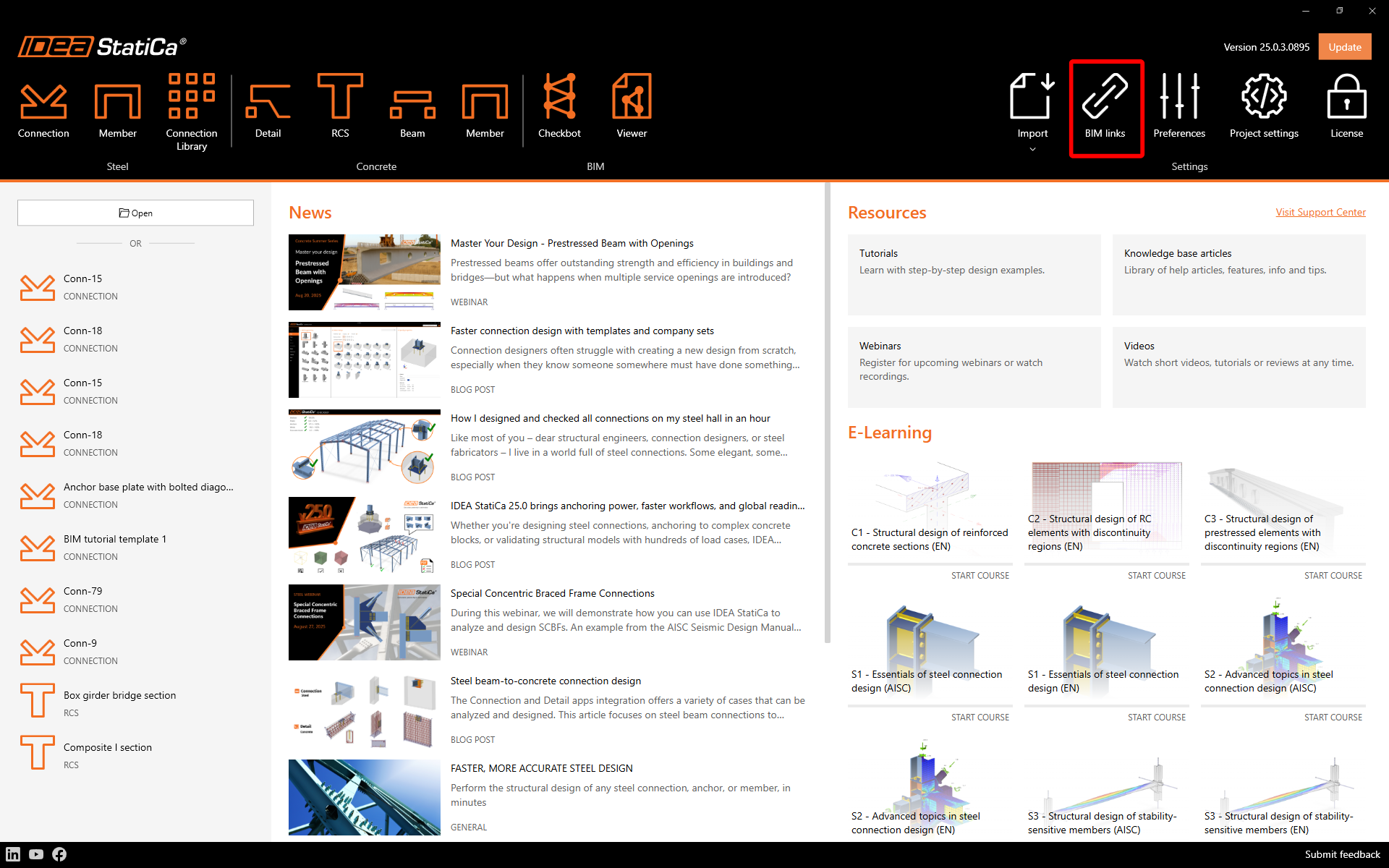
Ouvrez IDEA StatiCa et allez à l'onglet BIM et ouvrez l'outil d'installation des liens BIM (Activation du lien BIM...).
Une notification avec le texte « Voulez-vous autoriser cette application à apporter des modifications à votre appareil ? » peut apparaître. Dans ce cas, veuillez confirmer avec le bouton Oui.
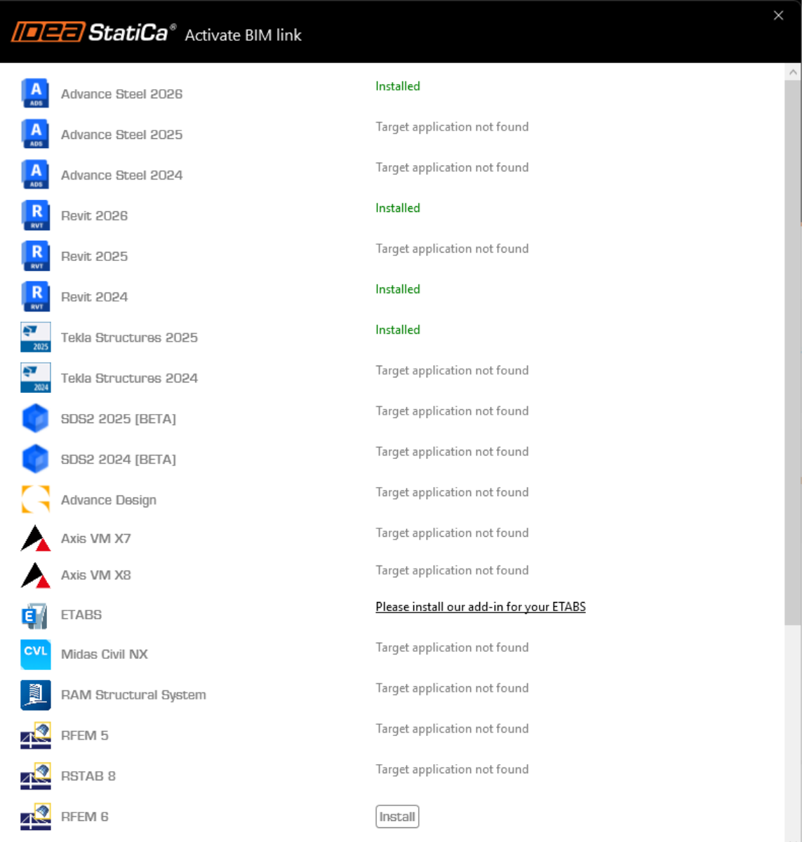
Le lien BIM pour le logiciel sélectionné (si trouvé) sera installé. L'écran vous montrera aussi le statut d'autres liens BIM qui peuvent être déjà installés.
Comment utiliser le lien
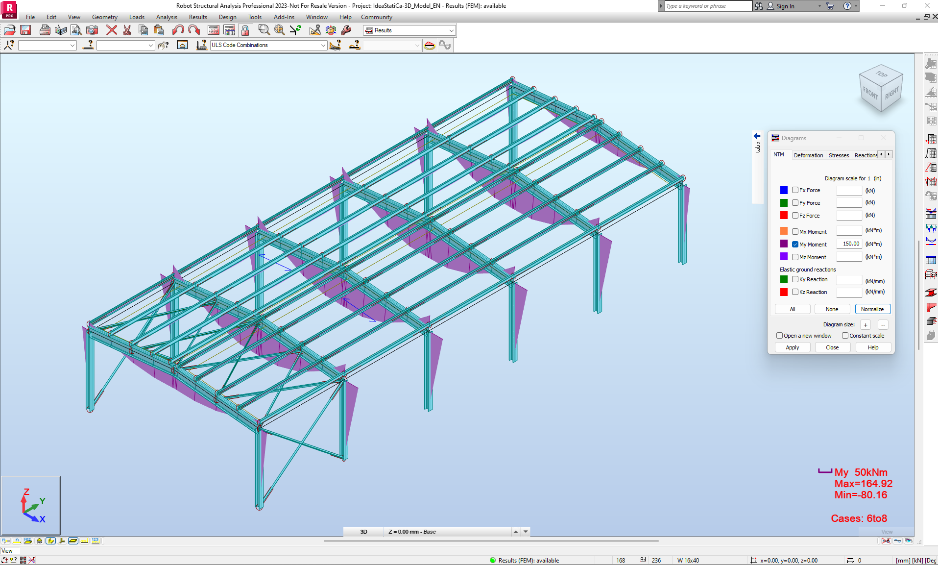
Téléchargez le projet joint, ouvrez-le dans Robot Structural Analysis et lancez le calcul pour obtenir les efforts internes sur la structure.
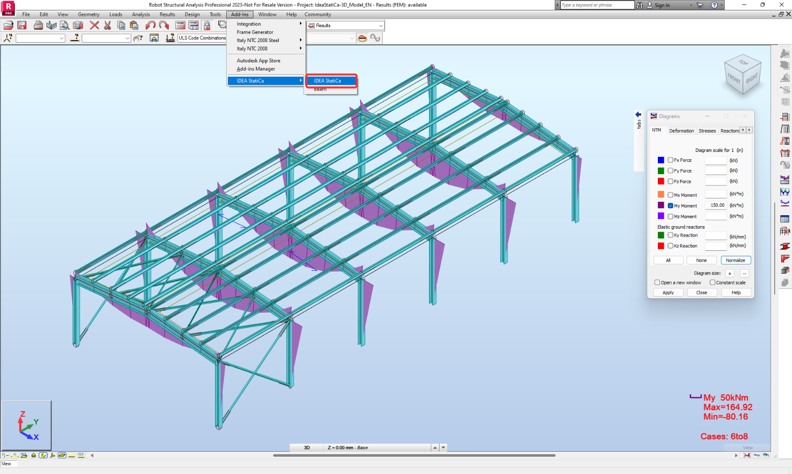
Pour lancer le Checkbot, utilisez le bouton Add-Ins et trouvez l'icône IDEA StatiCa.
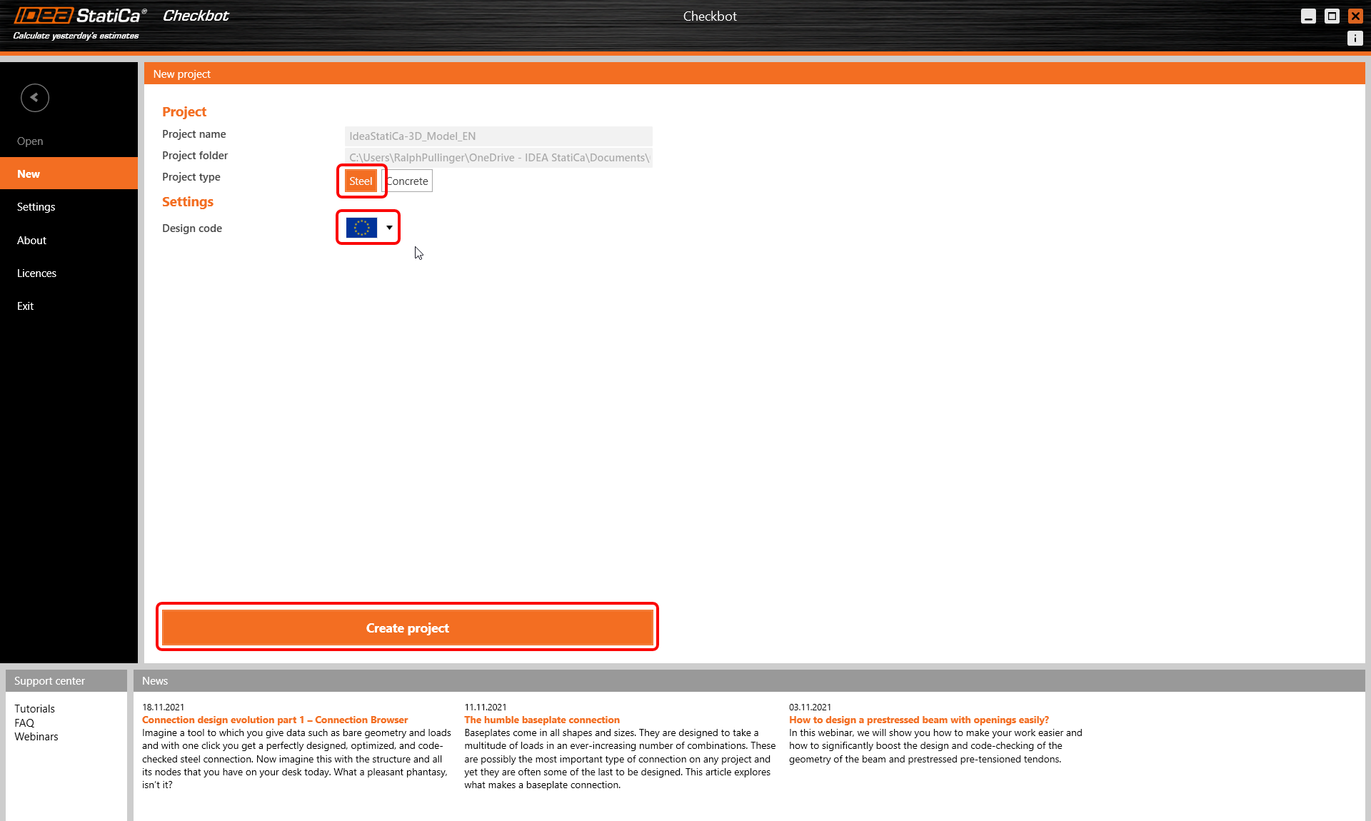
Après avoir lancé l'application Checkbot, sélectionnez Nouveau avec le type de projet Acier et le code de calcul EN. Cliquez ensuite sur Créer le projet.
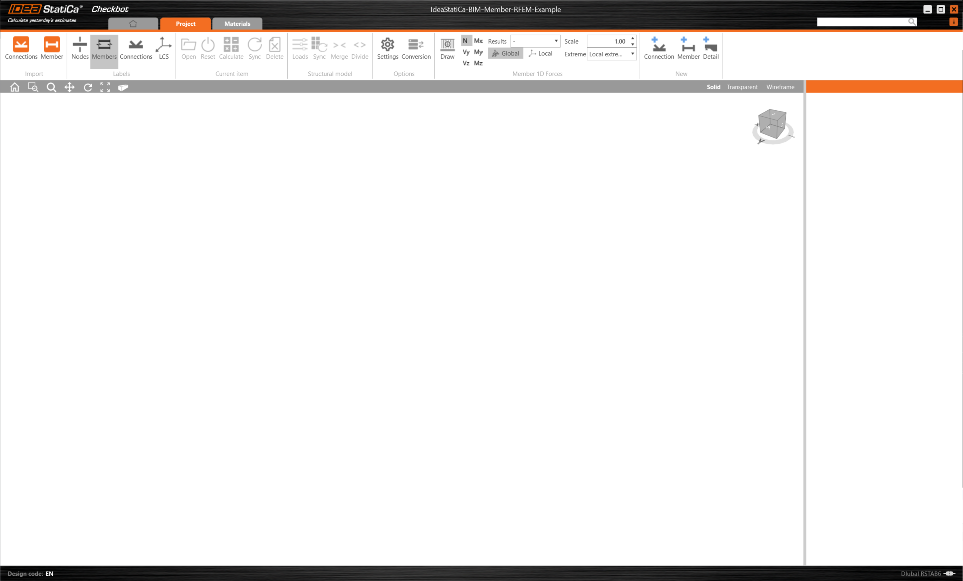
Importation
Le nouveau projet Checkbot est prêt à importer les assemblages et les éléments depuis Robot Structural Analysis.
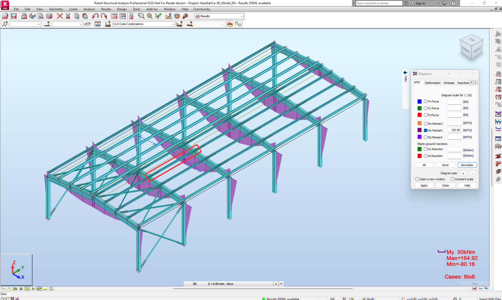
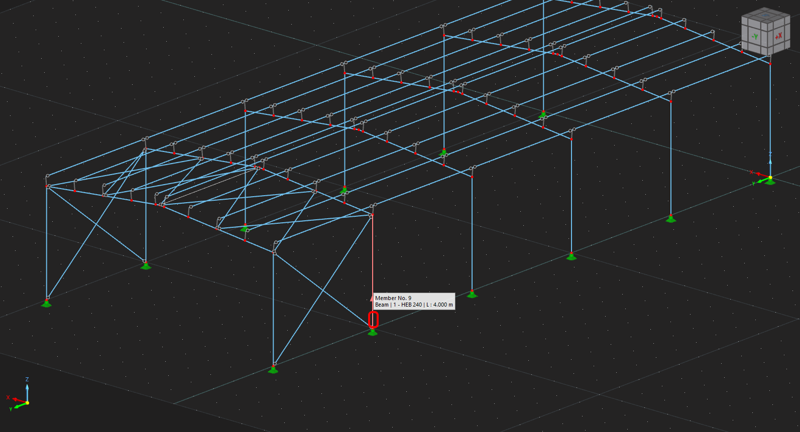
Dans Robot Structural Analysis, sélectionnez l'un des éléments intérieurs, comme indiqué sur l'image suivante.
Géométrie
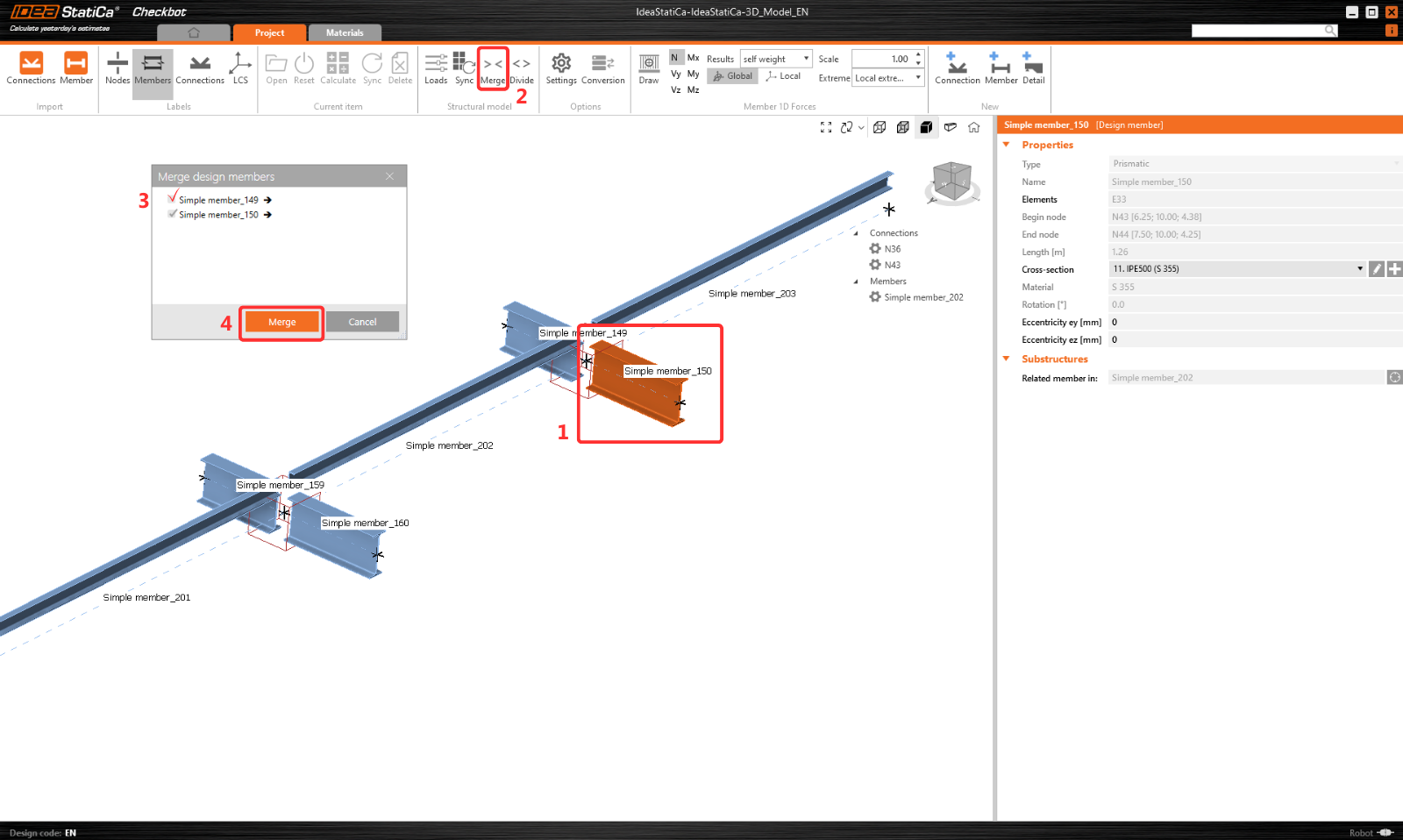
Dans Checkbot, vous pouvez fusionner des éléments séparés en un élément continu. Fusionnez les deux poutres porteuses. Sélectionnez l'élément associé 150, cliquez sur la commande Fusionner.
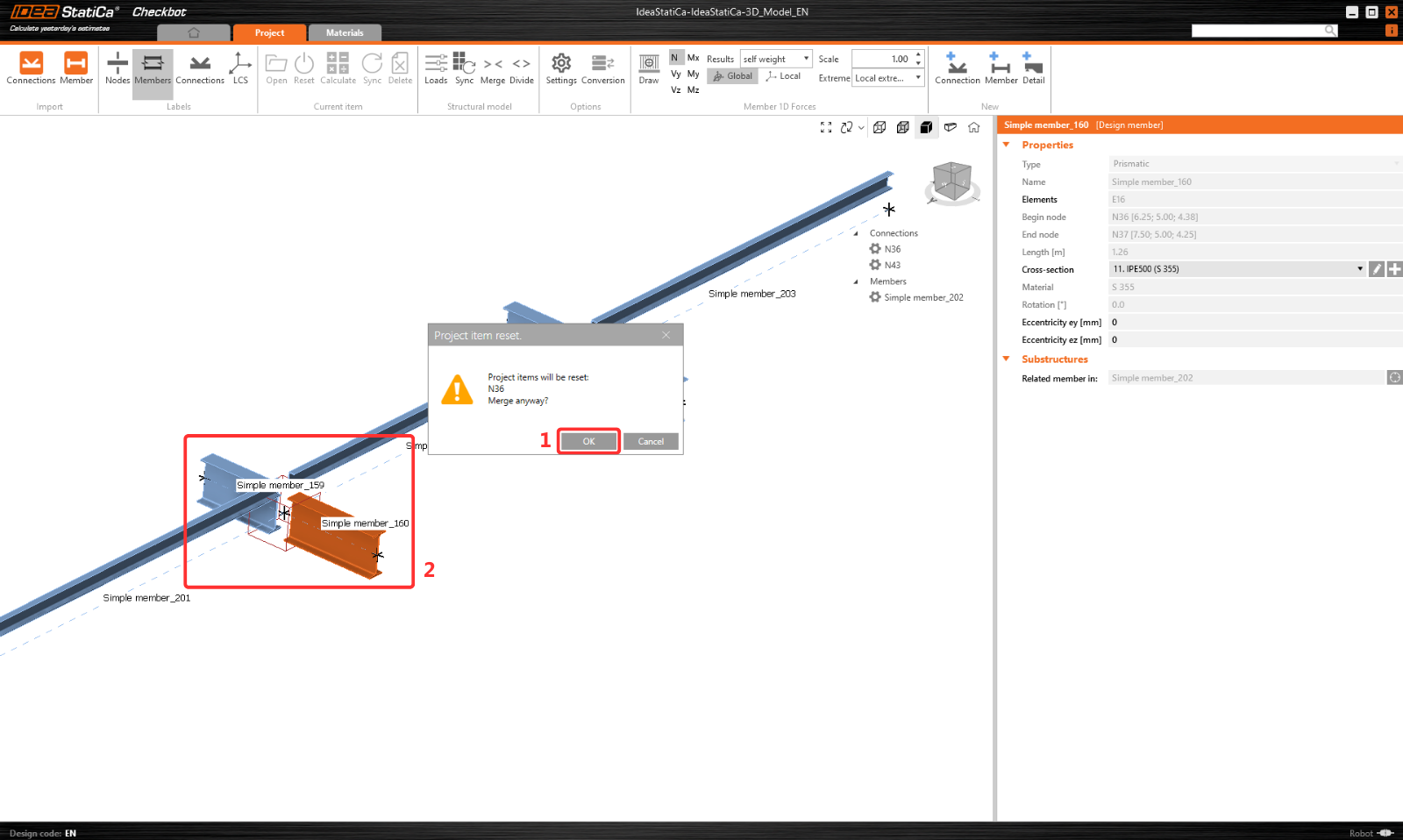
Même opération de fusion que précédemment pour l'élément associé 160.
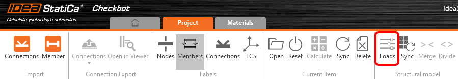
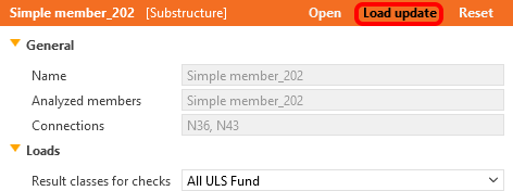
Vous pouvez contrôler les cas de charge et les combinaisons qui seront utilisés pour l'analyse dans l'application Checkbot en cliquant sur Charges et en gérant la colonne Classes de résultats pour les vérifications.
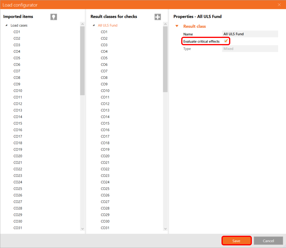
Remarque : Par défaut, la fonction Évaluer les résultats critiques est activée, ce qui filtre les cas de charge et combinaisons non déterminants afin d'accélérer le calcul. Vous pouvez la désactiver, et toutes les combinaisons seront incluses dans le calcul. Vous pouvez supprimer ou ajouter des éléments via un clic droit ou par glisser-déposer entre les colonnes.
En savoir plus sur cette fonctionnalité et l'algorithme sous-jacent.
Pour appliquer les modifications, vous devez également cliquer sur le bouton Mise à jour des charges.
Calcul
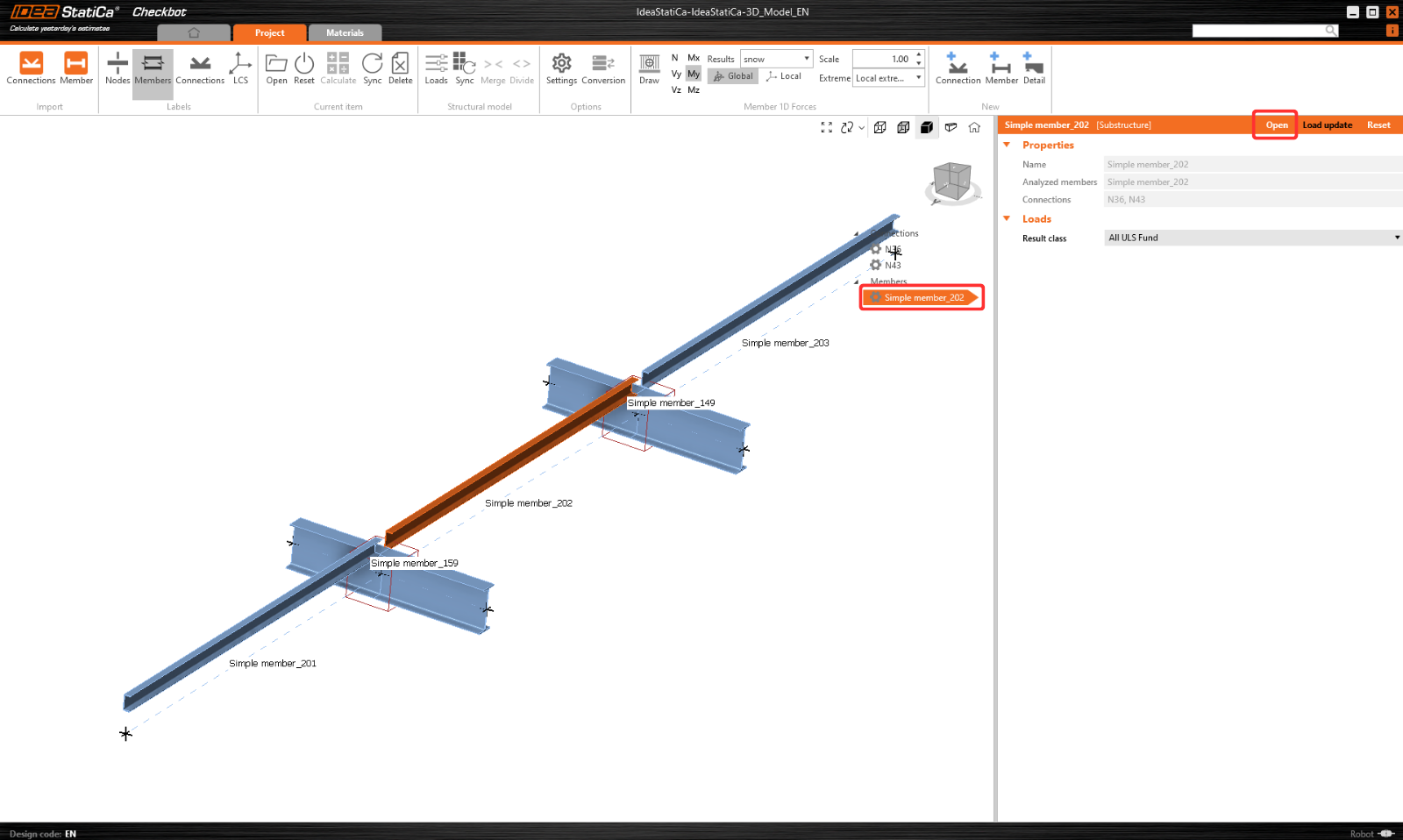
Sélectionnez maintenant l'élément 202 et cliquez sur Ouvrir pour démarrer le calcul.
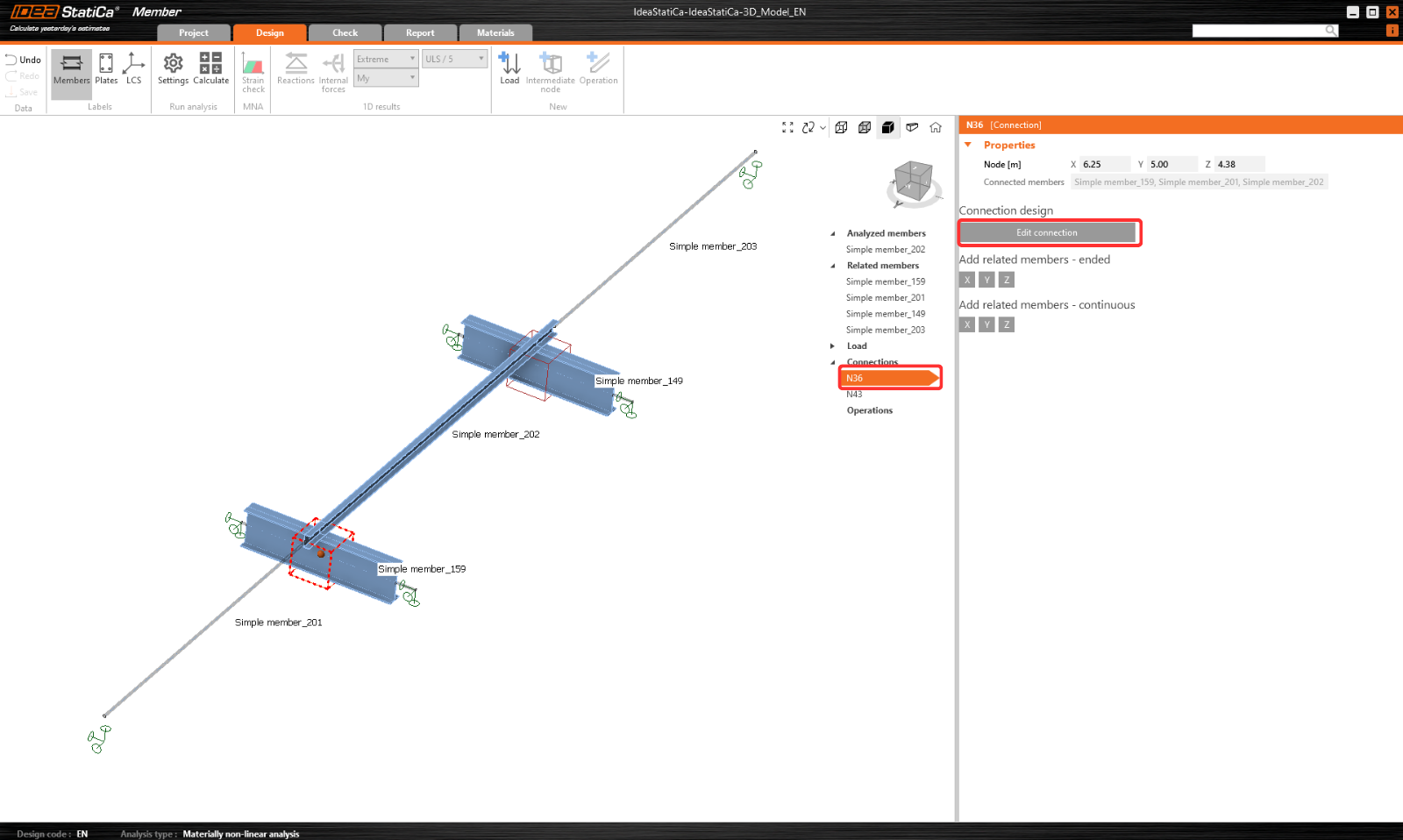
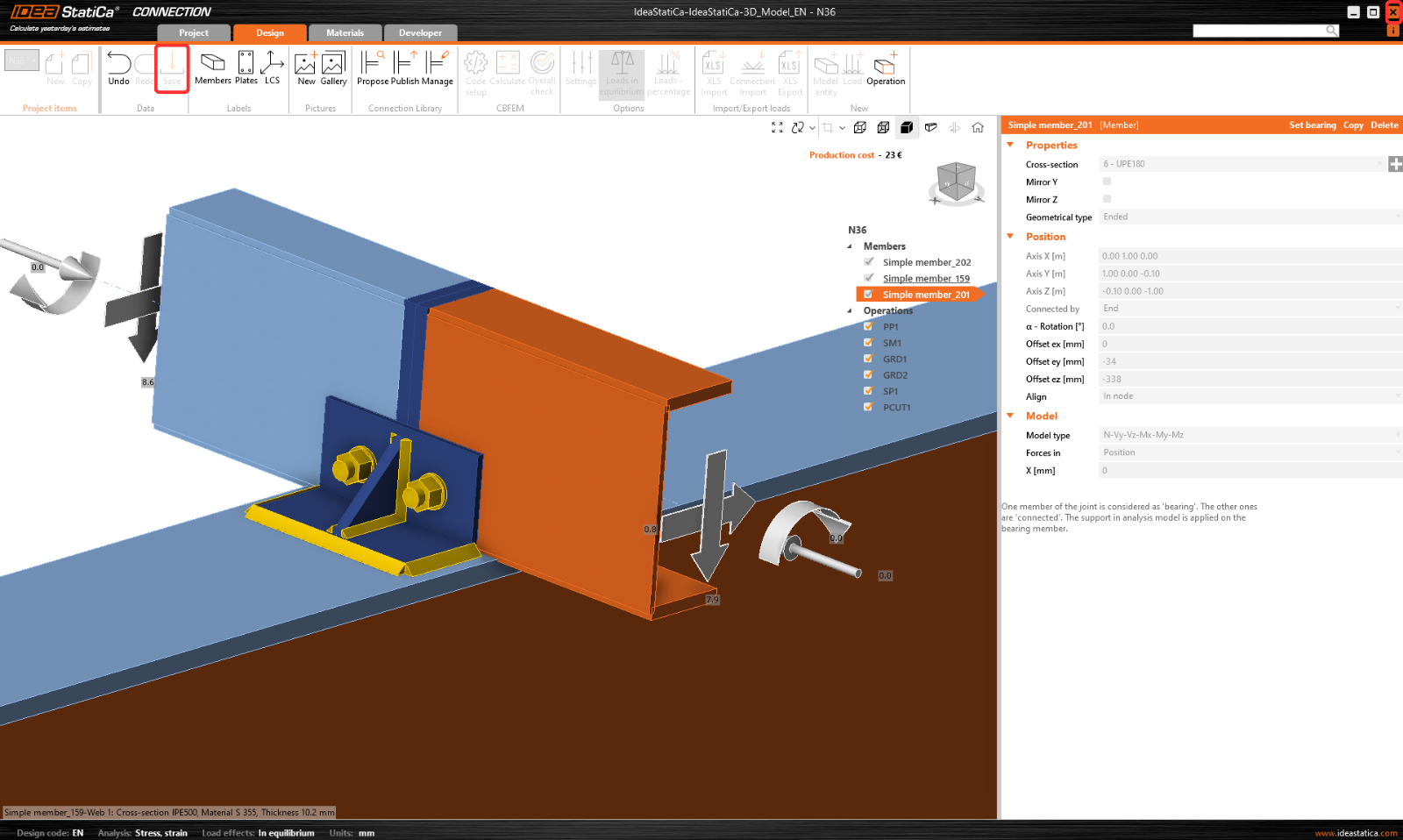
Calculez d'abord l'assemblage N36. Sélectionnez-le et cliquez sur Modifier l'assemblage pour ouvrir l'application Connection.
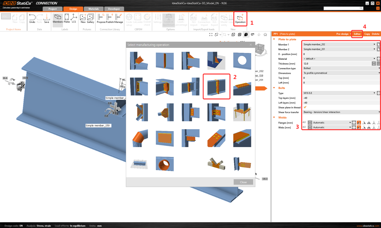
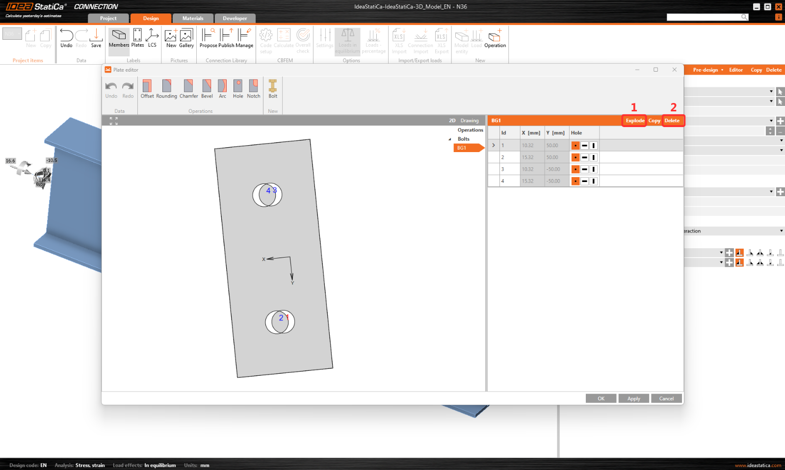
Cliquez sur Opération et sélectionnez Plaque à plaque. Définissez les valeurs conformément à l'image. Cliquez ensuite sur Éditeur.
Cliquez sur Éclater et supprimez les boulons 1 et 3.
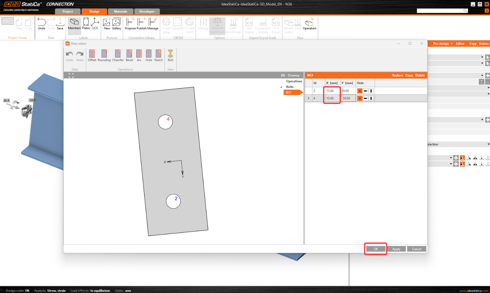
Et définissez les coordonnées des boulons 2 et 4 conformément à l'image. Confirmez les modifications en cliquant sur OK.
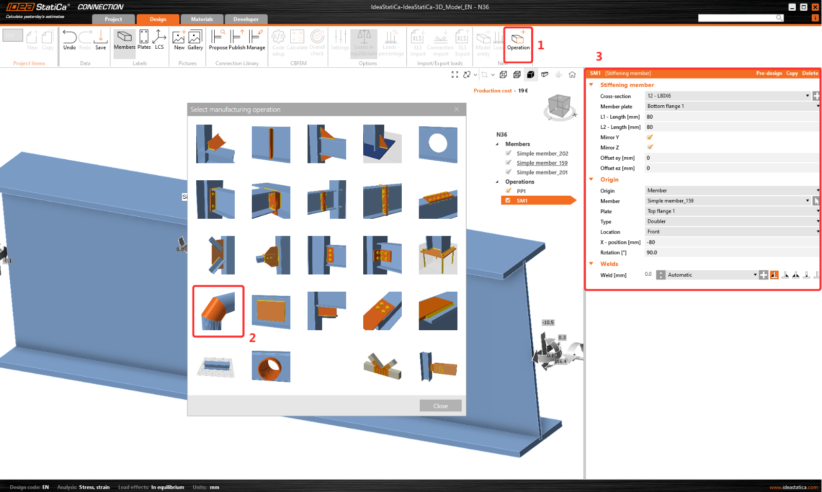
L'opération suivante est l'élément de raidissement, définissez le profilé en L L80x6 avec les valeurs suivantes.
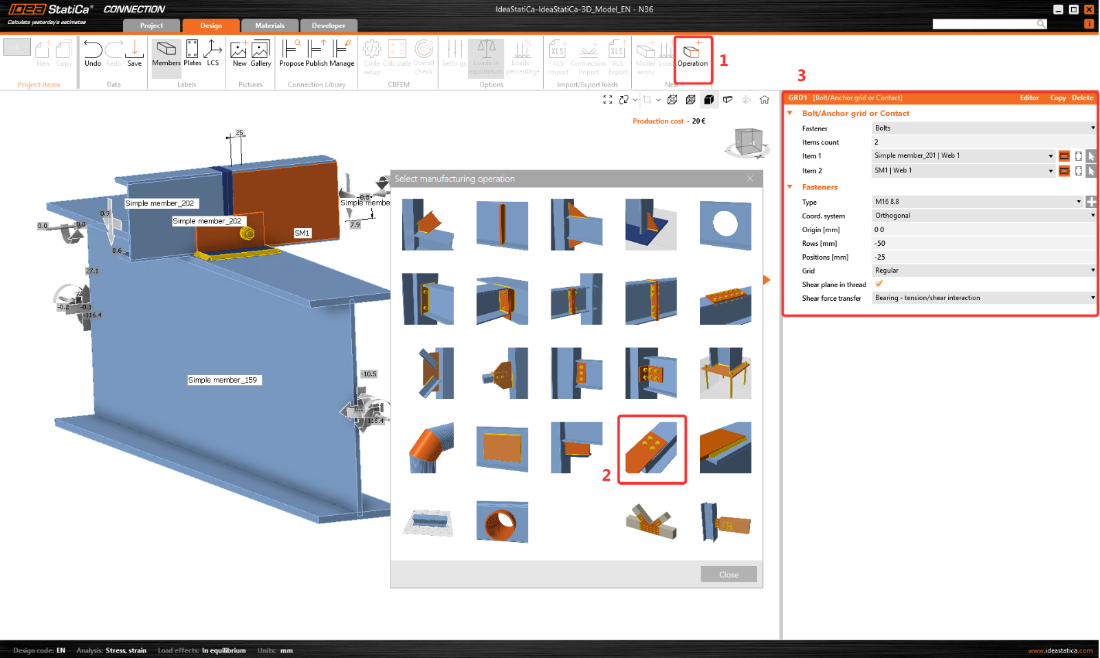
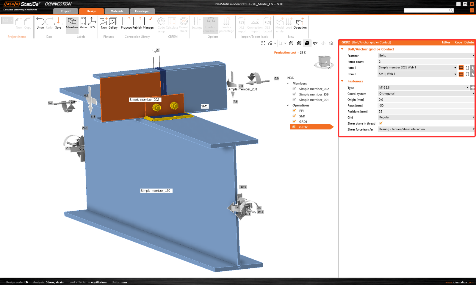
Ajoutez l'opération Grille de boulons/ancrages et modifiez les paramètres.
Copiez cette opération et modifiez les valeurs sélectionnées.
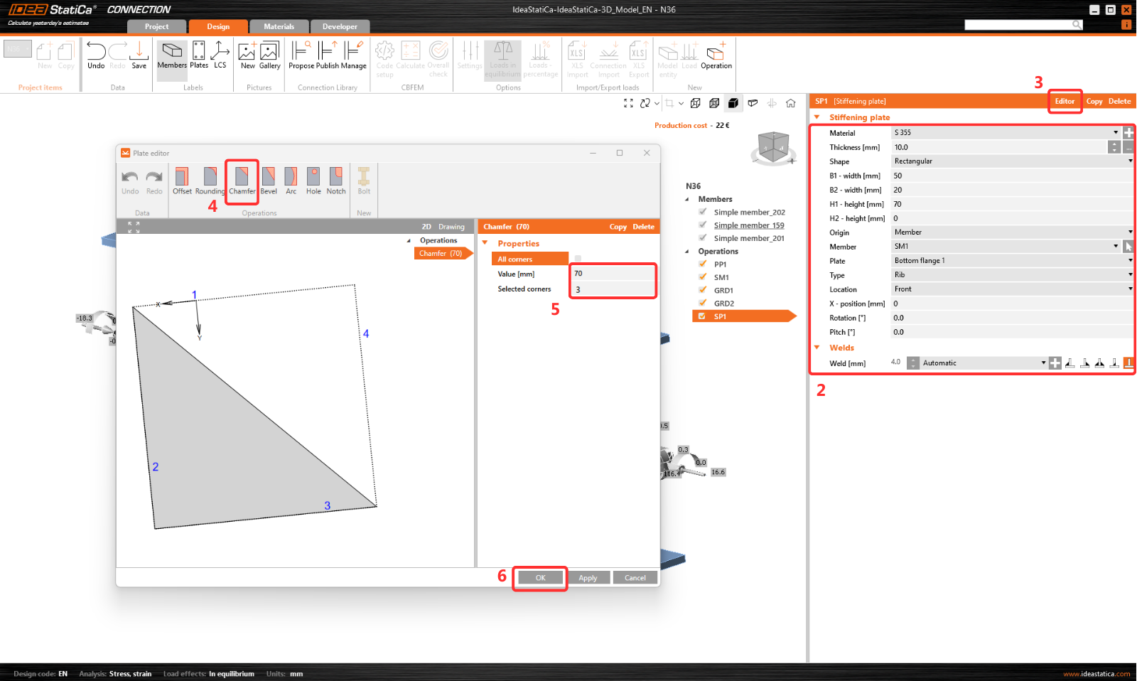
Ajoutez maintenant une Plaque de raidissement à l'assemblage.
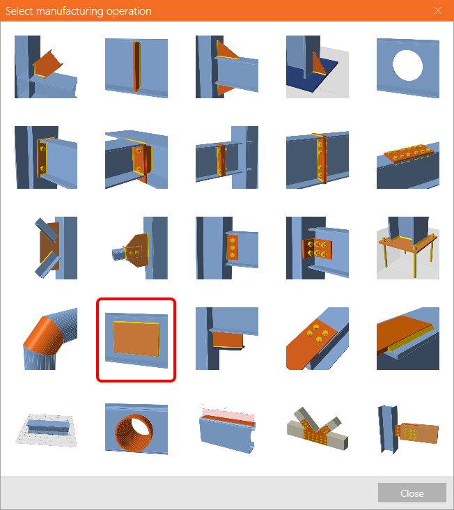
Et modifiez sa forme dans l'Éditeur de plaque. Ici, ajoutez l'opération Chanfrein pour découper la plaque.
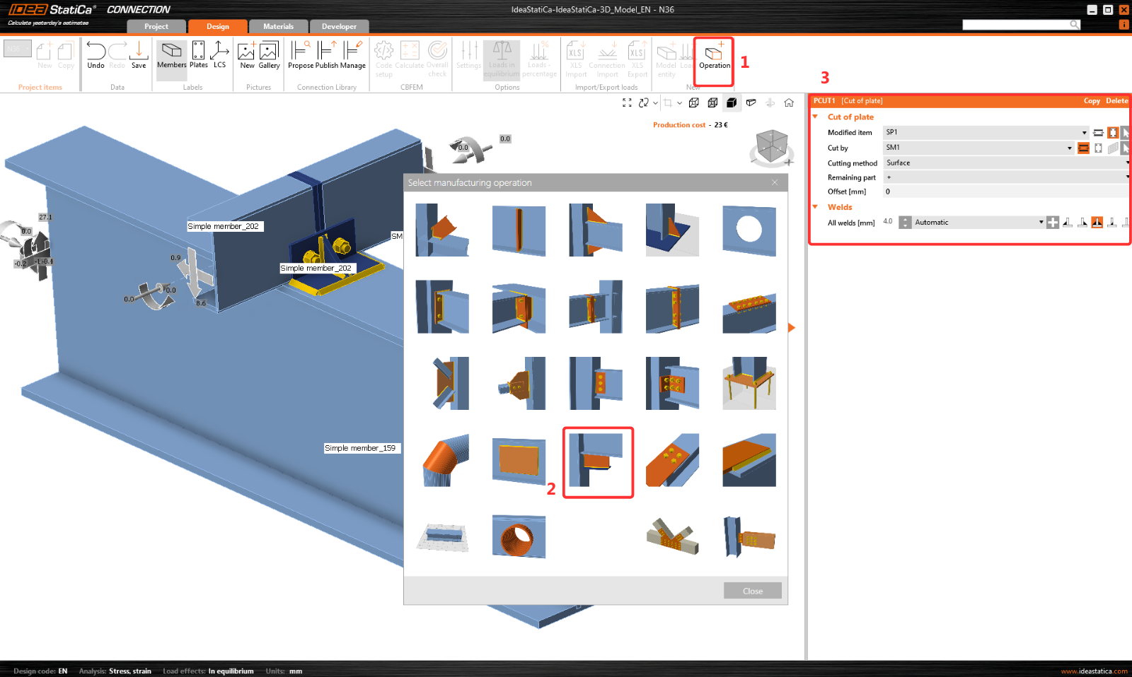
La dernière opération est la Coupe de plaque.
Cliquez maintenant sur Enregistrer et fermez le module Connection.
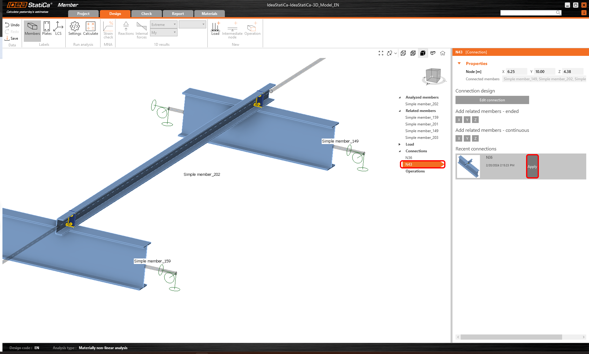
Comme nous avons un assemblage similaire dans les deux nœuds, vous pouvez copier le calcul terminé vers le nœud N43 en cliquant sur Appliquer.
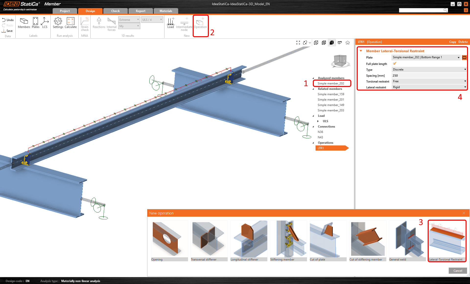
Étant donné que des panneaux de toiture stabilisent la panne analysée, ajoutez l'opération Retenue au déversement latéral pour la simuler et définissez les paramètres.
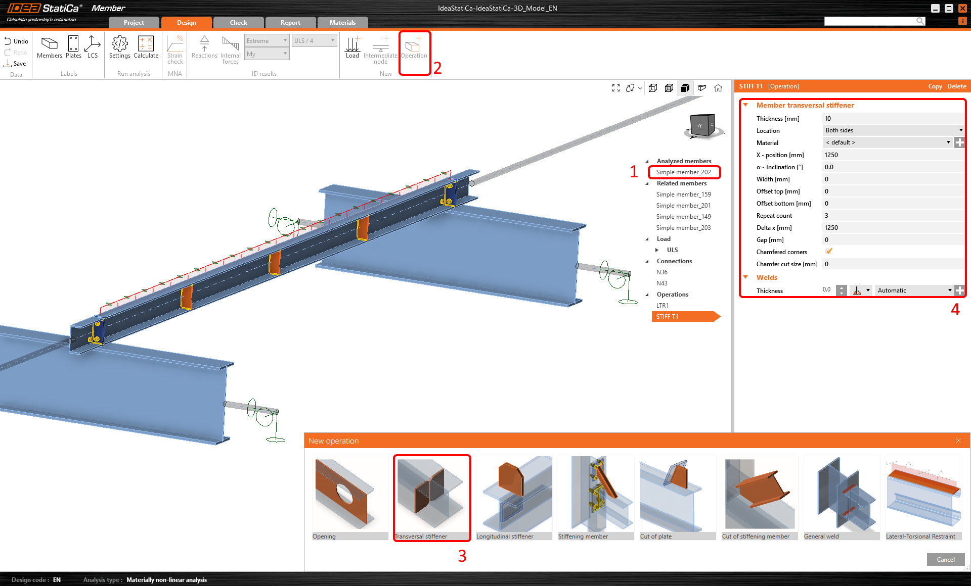
Ajoutez ensuite l'opération Raidisseur transversal.
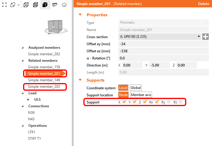
Pour assurer le comportement structurel correct des éléments associés, définissez les appuis des pannes de raccordement 201 et 203 sur X, Y, Z et Rx.
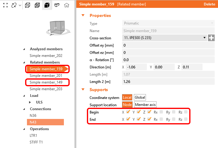
De même, pour les éléments porteurs 149 et 159, définissez les appuis sur X, Y, Z.
Vérification normative
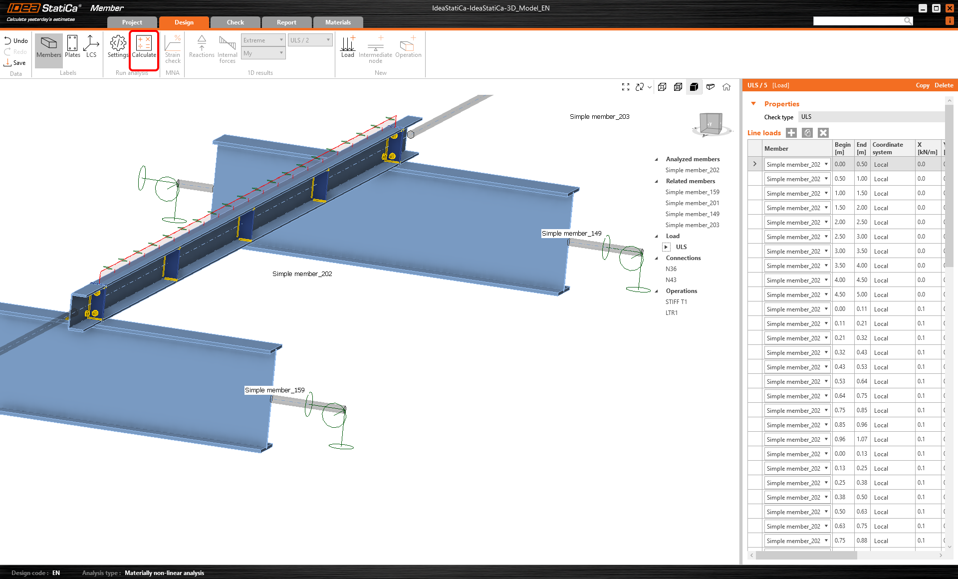
Le modèle d'élément est maintenant prêt pour l'analyse.
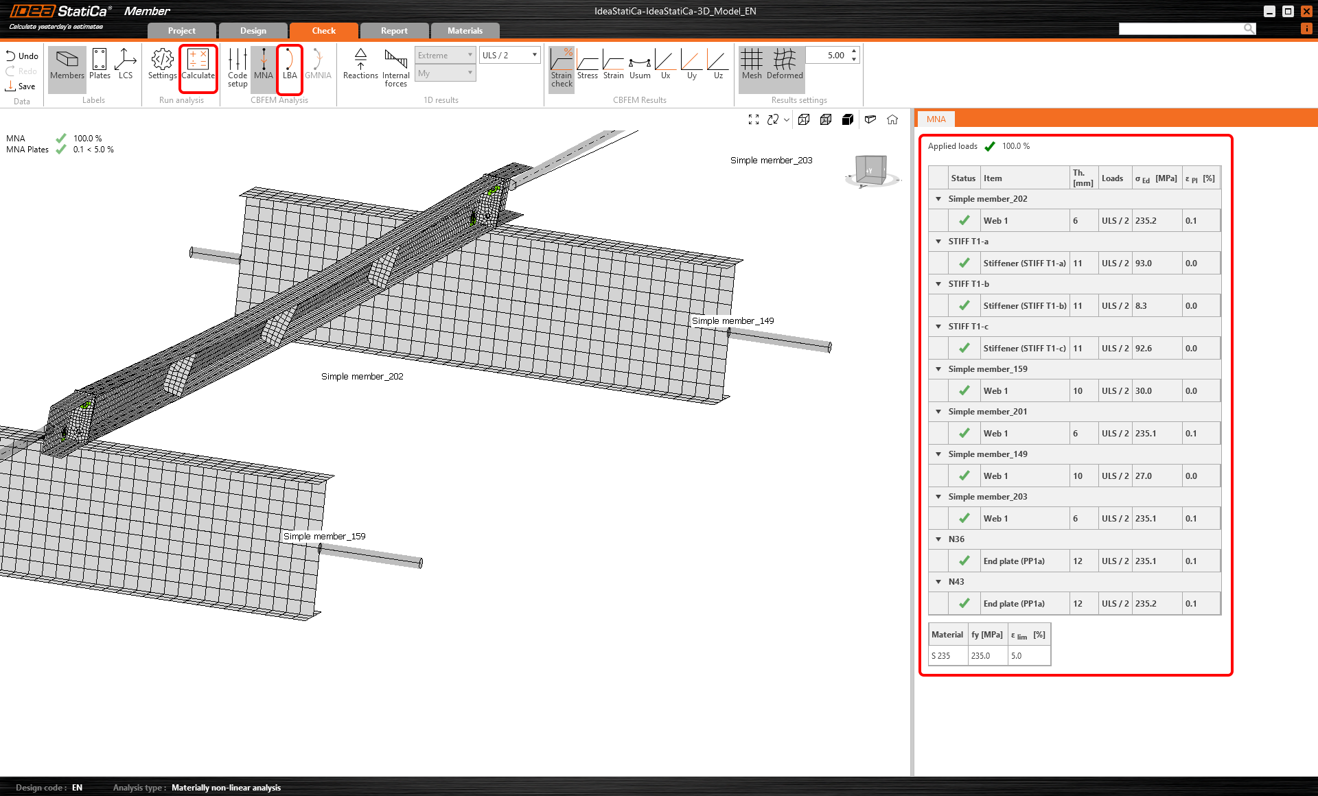
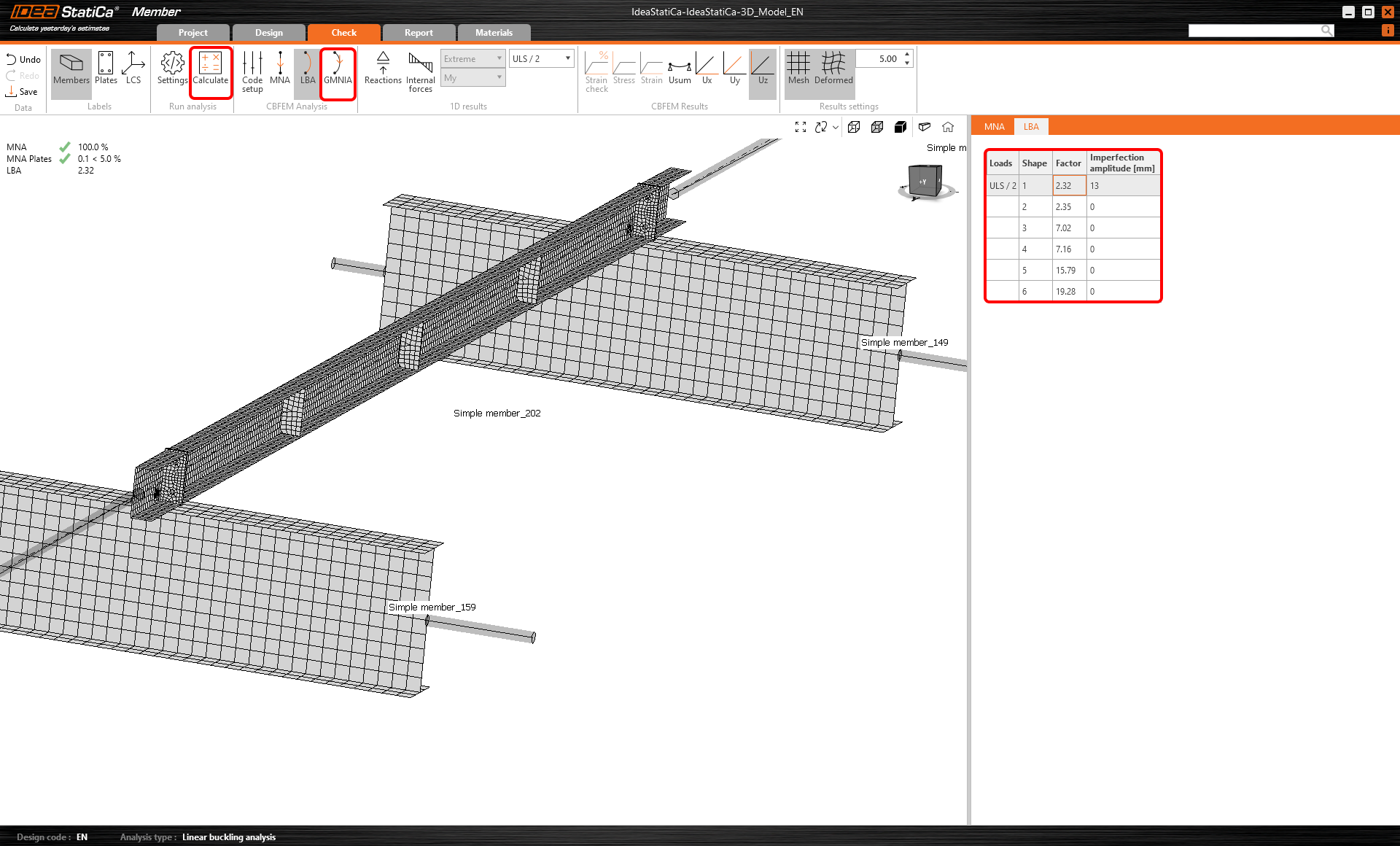
Lancez l'analyse MNA (matériellement non linéaire) avec le bouton Calculer.
La deuxième analyse est l'LBA (analyse de flambement latéral), où nous obtenons un facteur critique inférieur à 15. Ce résultat montre la nécessité de réaliser l'analyse GMNIA (analyse géométriquement et matériellement non linéaire).
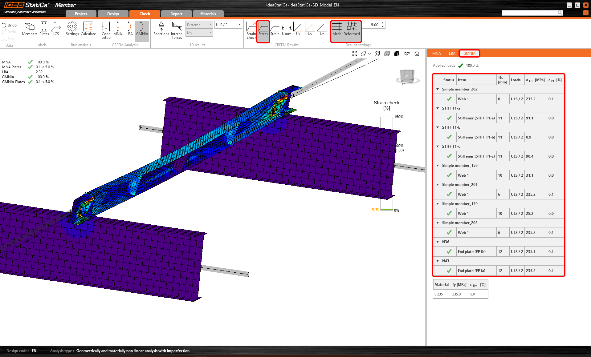
Avant de lancer l'analyse GMNIA (géométriquement et matériellement non linéaire), renseignez la valeur de l'amplitude d'imperfection. Étant donné que le déversement est étudié ici, le facteur k0 = 0,5 peut être utilisé. Une amplitude de 0,5x5000/200 = 12,5 mm peut être appliquée au premier mode de flambement.
En savoir plus sur :
- Comment saisir les imperfections dans Member
- Stabilité des éléments dans IDEA StatiCa Member.
- Déversement
Une fois l'analyse terminée, vous pouvez consulter les vérifications normatives finales, y compris les imperfections.
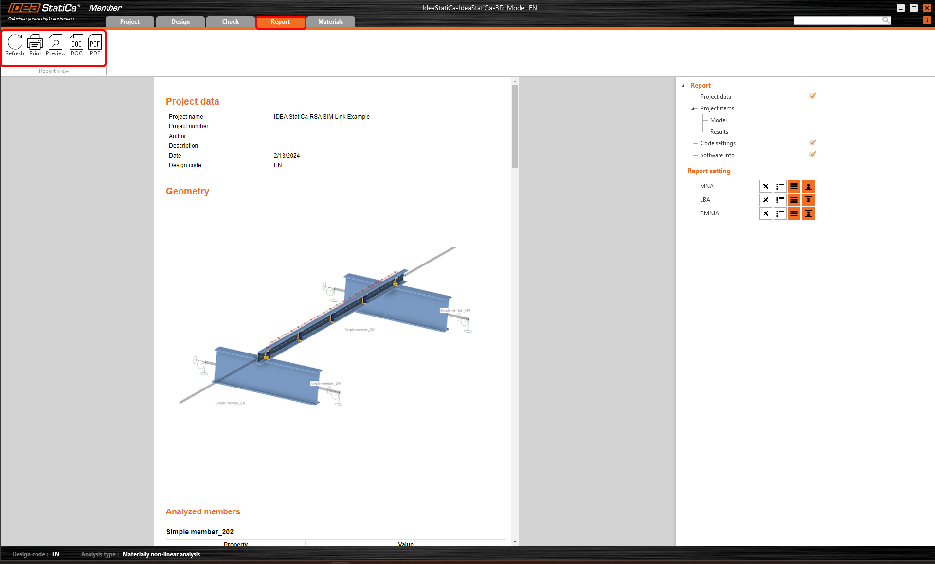
Rapport
Enfin, accédez à l'onglet Rapport. IDEA StatiCa propose un rapport entièrement personnalisable, pouvant être imprimé ou enregistré au format .doc modifiable.
Synchroniser les éléments
Parfois, des modifications sont apportées à votre modèle EF/BIM, comme une section d'élément différente ou des charges modifiées. Ces modifications peuvent être synchronisées entre Checkbot et le modèle EF/BIM.
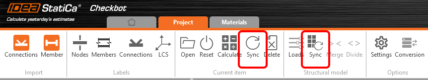
Deux alternatives sont possibles :
- Synchroniser l'élément courant (si un ou plusieurs assemblages sont sélectionnés)
- Synchroniser l'ensemble du modèle structurel importé
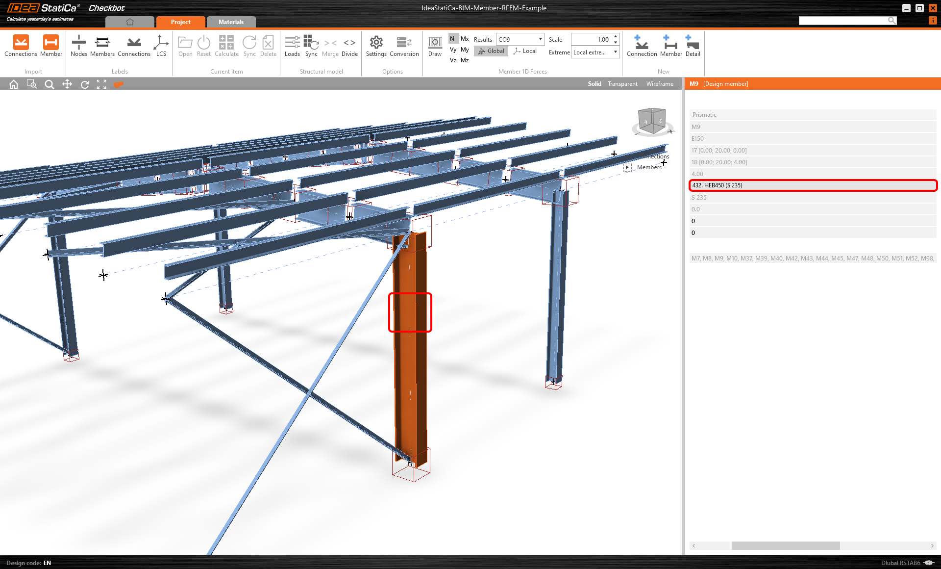
Pour tester cette fonctionnalité, vous pouvez modifier la taille ou la forme de la section d'un élément dans votre application EF/BIM, ou modifier un cas de charge ou une combinaison, etc. : remplacez les poteaux par une section plus grande. N'oubliez pas de relancer l'analyse du modèle EF.
Dans Checkbot, sélectionnez les éléments modifiés (il peut y en avoir plusieurs) et, depuis le panneau Élément courant, sélectionnez Sync.
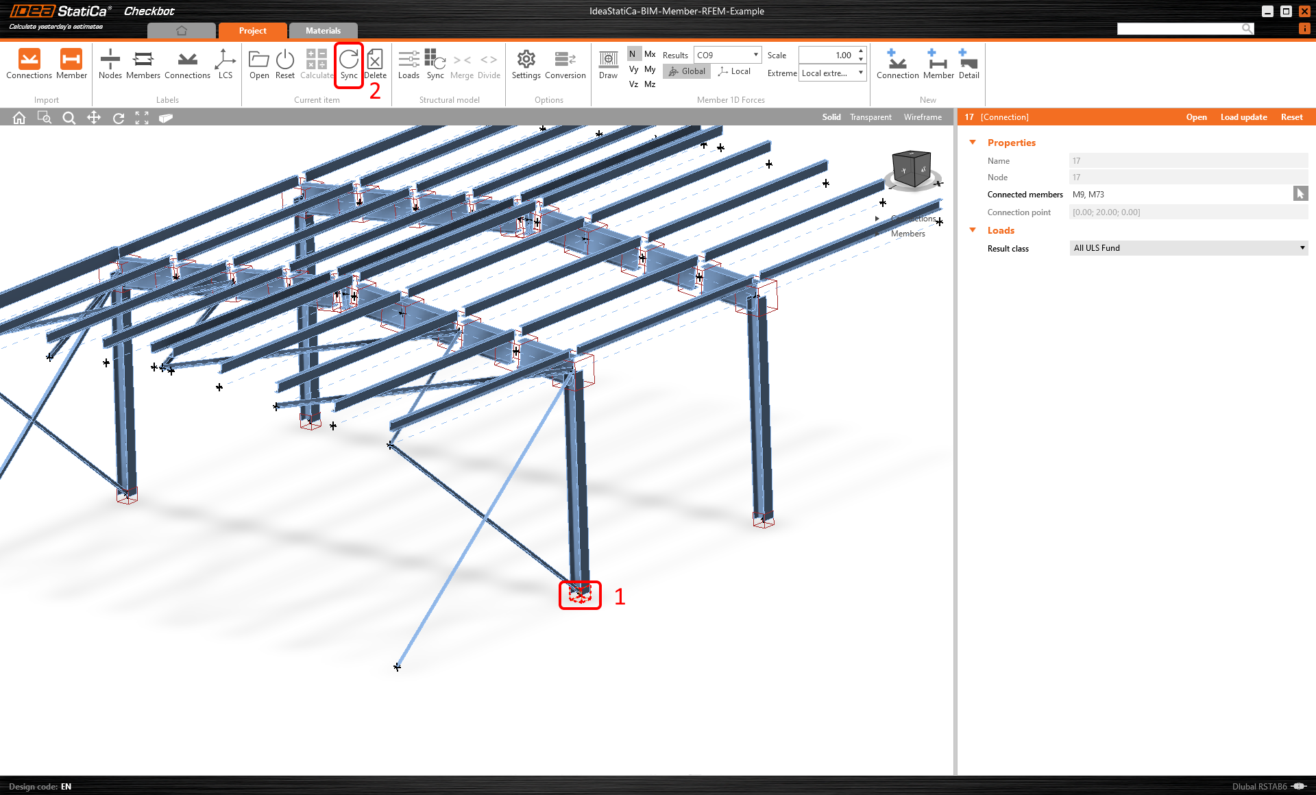
Le projet Checkbot sera mis à jour, la conception des éléments (et des assemblages) est conservée, mais les résultats seront invalidés. Vous pouvez constater que le poteau est maintenant mis à jour, conformément à la modification apportée dans le modèle EF.
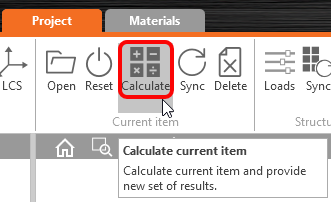
Effectuez simplement à nouveau la vérification normative de l'élément mis en évidence en sélectionnant Calculer dans le panneau Élément courant. N'oubliez pas que des modifications importantes du modèle peuvent nécessiter des étapes de validation supplémentaires pour les éléments concernés (comme indiqué ci-dessus).
Si les éléments ne donnent pas les résultats souhaités, vous pouvez les rouvrir pour optimiser la conception (c'est-à-dire renforcer si la vérification normative n'est pas satisfaite, ou alléger si le taux de travail est trop faible).
Vous avez réussi à lier Robot Structural Analysis avec IDEA StatiCa Member via Checkbot.
En savoir plus sur les limitations connues du lien BIM Robot Structural Analysis.