Vérification des composants d'assemblage acier (AS)
Les boulons, boulons précontraints et soudures sont vérifiés selon AS 4100–2020, Chapitre 9. La surface d'appui en béton selon AS3600:2018 – Chapitre 12.6. La vérification des ancrages est effectuée selon AS 5216:2018. Le dimensionnement de la bêche et le transfert de l'effort tranchant à la base du poteau par frottement sont conformes à la publication : Gianluca Ranzi, Peter Kneen: Design of Pinned Column Base Plates, Journal of the Australian Steel Institute, vol. 36, no. 2, septembre 2002.
Vérification normative des plaques acier selon les normes australiennes
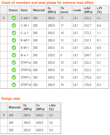
La vérification des déformations est effectuée sur les éléments finis de coque simulant les plaques. La limite d'élasticité est réduite par le facteur de capacité.
La contrainte équivalente résultante (HMH, von Mises) et la déformation principale plastique sont calculées sur les plaques. Lorsque la limite d'élasticité (multipliée par le facteur de capacité ϕ = 0,9, modifiable dans la configuration du code) est atteinte sur le diagramme bilinéaire du matériau, la vérification de la déformation plastique équivalente est effectuée. La valeur limite de 5 % est suggérée dans l'Eurocode (EN1993-1-5 Ann. C, Par. C8, Note 1). Cette valeur peut être modifiée dans la configuration du code, mais les études de vérification ont été réalisées pour cette valeur recommandée.
L'élément de plaque est divisé en cinq couches, et le comportement élastique/plastique est étudié dans chacune d'elles. Le programme affiche le résultat le plus défavorable parmi toutes les couches.
La méthode CBFEM peut fournir une contrainte légèrement supérieure à la limite d'élasticité. La raison en est la légère inclinaison de la branche plastique du diagramme contrainte-déformation, utilisée dans l'analyse pour améliorer la stabilité du calcul d'interaction. Cela ne pose pas de problème pour la conception pratique. La déformation plastique équivalente est dépassée à une contrainte plus élevée, et l'assemblage ne satisfait de toute façon pas aux exigences.
Vérification normative des boulons et boulons précontraints selon les normes australiennes
Les forces dans les boulons, y compris les efforts de levier, sont déterminées par analyse par éléments finis. Les résistances des boulons sont vérifiées selon les dispositions normatives.
Boulons
Les boulons sont vérifiés conformément au Chapitre 9.2 Design of bolts. L'effort de traction et l'effort de cisaillement dans chaque boulon sont déterminés par analyse par éléments finis. Les efforts de levier sont pris en compte conformément à la Clause 9.1.8. Les efforts de levier sont déterminés par analyse par éléments finis. Chaque plan de cisaillement est vérifié individuellement. L'appui de la pièce est vérifié par rapport à la somme des efforts de cisaillement dans les plans voisins.
Boulon en cisaillement
Un boulon soumis à un effort de cisaillement de calcul est dimensionné conformément à la Cl. 9.2.2.1 et doit satisfaire :
\[ V_f^* \le \phi V_f \]
où :
- Vf* – effort de cisaillement de calcul
- ϕ = 0,8 – facteur de capacité (Tableau 3.4) modifiable dans la configuration normative
- Vf = 0,62 fuf A – résistance nominale au cisaillement d'un boulon
- fuf – résistance minimale à la traction du boulon telle que spécifiée dans le Tableau 9.2.1
- A – aire d'un boulon égale soit à Ac soit à Ao, qui sont respectivement l'aire au diamètre minimal du boulon telle que définie dans AS 1275 ou l'aire nominale de la tige lisse du boulon. Chaque plan de cisaillement est vérifié individuellement.
La valeur de Ac est approximée dans le logiciel par la fonction :
Ac = 0,0000163 · As2 + 0,91682 · As − 0,85375
La différence maximale est de 0,8 mm2 ou 0,5 %.
Le facteur de réduction donné dans le Tableau 9.2.2.1 pour tenir compte de la longueur d'un assemblage à recouvrement boulonné est égal à 1,0. La réduction est appliquée automatiquement en vérifiant chaque boulon individuellement.
Conformément à la Cl. 9.2.2.5, pour les assemblages dans lesquels les plaques de remplissage dépassent 6 mm d'épaisseur, la résistance nominale au cisaillement d'un boulon doit être réduite de 15 %. Pour un assemblage à plans de cisaillement multiples, la réduction est appliquée à tous les plans de cisaillement.
Boulon en traction
Un boulon soumis à un effort de traction de calcul est dimensionné conformément à la Cl. 9.2.2.2 et doit satisfaire :
\[ N_{tf}^* \le \phi N_{tf} \]
où :
- Ntf* – effort de traction de calcul
- ϕ = 0,8 – facteur de capacité (Tableau 3.4) modifiable dans la configuration normative
- Ntf = As fuf – résistance nominale à la traction d'un boulon
- As – aire de contrainte en traction d'un boulon telle que spécifiée dans AS 1275
- fuf – résistance minimale à la traction du boulon telle que spécifiée dans le Tableau 9.2.1
Boulon soumis à une combinaison de cisaillement et de traction
Un boulon devant résister simultanément à un effort de cisaillement de calcul et à un effort de traction de calcul est dimensionné conformément à la Cl. 9.2.2.3 et doit satisfaire :
\[ \left ( \frac{V_f^*}{\phi V_f} \right ) ^2 + \left ( \frac{N_{tf}^*}{\phi N_{tf}} \right ) ^2 \le 1.0 \]
où :
- ϕ = 0,8 – facteur de capacité (Tableau 3.4) modifiable dans la configuration normative
Pièce en appui
Une pièce soumise à un effort d'appui de calcul dû à un boulon en cisaillement est dimensionnée conformément à la Cl. 9.2.2.4 et doit satisfaire :
\[ V_b^* \le ϕ V_b \]
où :
- ϕ = 0,9 – facteur de capacité (Tableau 3.4) modifiable dans la configuration normative
- \( V_b = 3.2 d_f t_p f_{up} \le a_e t_p f_{up} \) – résistance nominale à l'appui d'une pièce
- df – diamètre du boulon
- tp – épaisseur de la pièce
- fup – résistance à la traction de la pièce
- ae – distance minimale entre le bord d'un trou et le bord d'une pièce, mesurée dans la direction de la composante de la force, plus la moitié du diamètre du boulon. Le bord d'une pièce est réputé inclure le bord d'un trou de boulon adjacent
Assemblages par friction
Pour les assemblages par friction, le glissement à l'état limite de service doit être limité et dimensionné conformément à la Cl. 9.2.3. Ces boulons doivent également être vérifiés en tant qu'assemblages par appui à l'état limite ultime. Un boulon soumis à un effort de cisaillement doit satisfaire :
\[ V_{sf}^* \le ϕ V_{sf} \]
où :
- ϕ = 0,7 – facteur de capacité (Chapitre 3.5.5) modifiable dans la configuration normative
- Vsf = μ Nti kh – résistance nominale au cisaillement d'un boulon
- μ = 0,35 – facteur de glissement tel que spécifié à la Clause 9.2.3.2, modifiable dans la configuration normative
- Nti – tension minimale du boulon à la mise en œuvre telle que spécifiée à la Clause 15.2.2.2
| Diamètre nominal du boulon | Précontrainte minimale du boulon [kN] |
| M16 | 95 |
| M20 | 145 |
| M24 | 210 |
| M30 | 335 |
| M36 | 490 |
| Autre | \(A_s \cdot 600\) MPa |
- k h – facteur pour différents types de trous, tel que spécifié aux Clauses 9.2.3.1 et 14.3.2
- k h = 1 pour les trous standard (+2 mm pour d f ≤ 24 mm, +3 mm sinon)
- k h = 0,85 pour les trous oblongs courts (longueur du trou ≤ max(1,33 d f, d f + 10 mm)) et les trous surdimensionnés
- k h = 0,70 pour les trous oblongs longs
Le nombre d'interfaces efficaces, nei, est toujours égal à 1, car chaque interface est vérifiée séparément.
Les boulons dans des assemblages par friction soumis à une combinaison de cisaillement et de traction doivent satisfaire :
\[ \left ( \frac{V_{sf}^*}{ϕ V_{sf}} \right ) + \left ( \frac{N_{tf}^*}{ϕ N_{tf}} \right ) \le 1.0 \]
où :
- Vsf* – effort de cisaillement de calcul sur le boulon dans le plan des interfaces
- Ntf* – effort de traction de calcul sur le boulon
- ϕ = 0,7 – facteur de capacité (Chapitre 3.5.5) modifiable dans la configuration normative
- Vsf – résistance nominale au cisaillement du boulon
- Ntf = Nti – résistance nominale à la traction du boulon égale à la tension minimale du boulon à la mise en œuvre
Les assemblages par friction doivent également être vérifiés à l'état limite ultime. Le type de boulon doit être modifié en appui – interaction traction/cisaillement, les charges augmentées en conséquence et l'assemblage doit être vérifié à nouveau.
Vérification normative des soudures selon les normes australiennes
Les soudures d'angle sont vérifiées conformément à AS 4100 - Chapitre 9.6. La résistance des soudures en bout à pleine pénétration (CJP) est supposée identique à celle du métal de base et n'est pas vérifiée.
Il est possible de définir des soudures bout à bout ou des soudures d'angle sur toute la longueur du bord, des soudures partielles ou des soudures intermittentes. Les soudures bout à bout sont supposées avoir la même résistance que l'élément soudé et ne sont pas vérifiées. Dans le cas des soudures d'angle, l'élément de soudure est inséré entre des liaisons d'interpolation reliant les platines entre elles. L'élément de soudure possède un diagramme de matériau élasto-plastique défini afin de redistribuer la contrainte sur la longueur de la soudure, de sorte que les soudures longues, les soudures multi-orientations ou le soudage sur une semelle non raidie présentent une résistance similaire à celle obtenue par calcul manuel. L'élément de soudure le plus sollicité est déterminant pour la vérification normative de la soudure.
Une soudure d'angle soumise à une force de calcul par unité de longueur de soudure, vw*, est dimensionnée conformément à l'article 9.6.3.10 et doit satisfaire :
\[ v_w^* \le ϕ v_w \]
où :
- ϕ = 0,8 – facteur de capacité (Chapitre 3.4) modifiable dans la configuration du code
- vw = 0,6 fuw tt – capacité nominale d'une soudure d'angle par unité de longueur
- fuw – résistance nominale à la traction du métal d'apport (Tableau 9.6.3.10 (A))
- tt – épaisseur de gorge de calcul
Le facteur de réduction, kr, est supposé égal à 1 (soudure de longueur inférieure à 1,7 m).
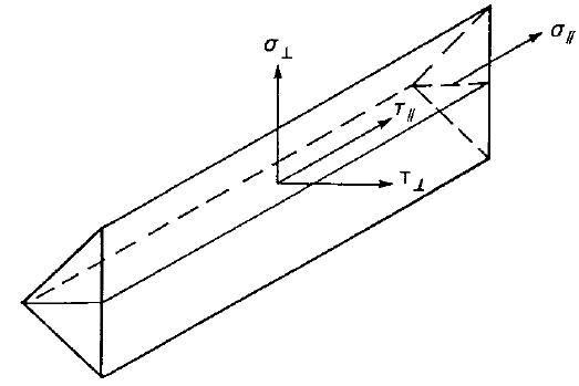
Les diagrammes de soudure affichent la contrainte selon la formule suivante :
\[ \sigma = \sqrt{ \sigma_{\perp}^2 + \tau_{\perp}^2 + \tau_{\parallel}^2 } \]
Vérification normative du bloc de béton selon les normes australiennes
Le béton sous la platine de base est simulé par un sol de Winkler à rigidité uniforme, qui fournit les contraintes de contact. La contrainte moyenne sur la zone chargée en contact avec la platine de base est utilisée pour la vérification en compression.
Surface d'appui du béton
La surface d'appui du béton est vérifiée conformément à AS3600 : 2018 – Cl. 12.6. La contrainte d'appui de calcul sur une surface en béton ne doit pas dépasser :
\[ ϕ f_b = ϕ 0.9 f'_c \sqrt{\frac{A_2}{A_1}} \le ϕ 1.8 f'_c \]
où :
- ϕ = 0,6 – facteur de capacité (Tableau 2.2) modifiable dans la configuration normative
- f'c – résistance caractéristique à la compression sur cylindre du béton à 28 jours
- A1 – aire d'appui
- A2 – plus grande aire de la surface d'appui géométriquement similaire et concentrique à A1. Les pentes latérales du tronc de pyramide sont de 1 longitudinalement et 2 transversalement par rapport à la direction de la charge.
La contrainte d'appui de calcul, σ, est égale à la contrainte moyenne sous la platine de base sur la zone en contact avec le béton.
Transfert de l'effort tranchant
L'effort tranchant au niveau de la platine de base est supposé être transféré du poteau à la fondation en béton par :
- Frottement entre la platine de base et le béton / le mortier de scellement
- Bêche
- Boulons d'ancrage
Transfert de l'effort tranchant par frottement
La capacité au cisaillement est calculée conformément à Gianluca Ranzi, Peter Kneen : Design of Pinned Column Base Plates, Journal of the Australian Steel Institute, vol. 36, n° 2, septembre 2002 – Chapitre 6.5.3, comme suit :
\[ ϕ V_f = ϕ μ N_c^* \]
où :
- ϕ = 0,8 – facteur de capacité
- μ = 0,55 – coefficient de frottement modifiable dans la configuration normative
- Nc* – effort axial de compression de calcul du poteau
Transfert de l'effort tranchant par bêche
Si l'effort tranchant est transféré par la bêche, celle-ci est modélisée par éléments finis, et ses plaques et soudures sont vérifiées par la Méthode des Éléments Finis et les composants de soudure. Des vérifications supplémentaires sont requises – résistance à l'appui du béton ; résistance du béton en rive.
Résistance à l'appui du béton
La résistance à l'appui du béton est vérifiée conformément à Gianluca Ranzi, Peter Kneen : Design of Pinned Column Base Plates, Journal of the Australian Steel Institute, vol. 36, n° 2, septembre 2002 – Chapitre 6.5.5 :
\[ ϕ_c V_b = 0.85 ϕ_c f'_c A_{sl} \]
où :
- ϕc = 0,6 – facteur de capacité pour le béton en appui, modifiable dans la configuration normative
- f'c – résistance caractéristique à la compression sur cylindre du béton à 28 jours
- Asl – aire projetée de la bêche encastrée dans la direction de la force, à l'exclusion de la partie de la bêche en contact avec le mortier de scellement au-dessus de l'élément en béton
Résistance du béton en rive
Si un effort tranchant agit vers un bord libre du béton, il convient de vérifier que le béton est capable de reprendre l'effort tranchant appliqué. La résistance du béton en rive est vérifiée conformément à Gianluca Ranzi, Peter Kneen : Design of Pinned Column Base Plates, Journal of the Australian Steel Institute, vol. 36, n° 2, septembre 2002 – Chapitre 6.5.5 :
\[ ϕ V_{ce} = ϕ 0.33 \sqrt{f'_c} A_{Vc} \]
où :
- ϕ = 0,85 – facteur de capacité
- f'c – résistance caractéristique à la compression sur cylindre du béton à 28 jours
- AVc – aire de contrainte effective définie par la projection d'un plan à 45° depuis les bords d'appui de la bêche jusqu'à la surface libre dans la direction de l'effort tranchant. L'aire d'appui de la bêche est exclue de l'aire projetée
Transfert de l'effort tranchant par ancrages
L'effort tranchant est supposé être transféré par les ancrages. L'effort dans chaque ancrage est déterminé par la Méthode des Éléments Finis. Chaque ancrage ou groupe d'ancrages est vérifié pour la rupture de l'acier en cisaillement, la rupture du béton en rive, la rupture du béton par effet de levier, et la combinaison traction-cisaillement si une traction est également présente.
Vérification normative des ancrages selon les normes australiennes
Les forces dans les ancrages, y compris les efforts de levier, sont déterminées par analyse par éléments finis, mais les résistances sont vérifiées à l'aide des dispositions normatives de l'AS 5216.
La vérification des ancrages est effectuée conformément à l'AS 5216:2018. Bien que la norme ne fournisse pas spécifiquement certaines formules pour les ancrages coulés en place, les formules sont identiques à celles de la SA TS 101:2015 où les ancrages coulés en place sont explicitement mentionnés. Le béton fissuré ou non fissuré peut être sélectionné dans la configuration normative. Le béton fissuré est supposé par défaut de manière conservative. La vérification de l'éclatement du cône de béton en traction et en cisaillement peut être ignorée dans la configuration normative, ce qui signifie que la force est supposée être transmise par le ferraillage. L'utilisateur dispose de la valeur de cette force. En raison de l'utilisation de la résistance à l'éclatement du cône de béton dans la formule de vérification de la rupture par poinçonnement du béton, cette vérification est également ignorée.
Les vérifications suivantes des ancrages sollicités en traction ne sont pas fournies et doivent être vérifiées à l'aide des informations contenues dans la Spécification Technique de Produit pertinente (essais conformément à l'AS 5216:2018 : Annexe A) :
- Rupture par arrachement de l'élément de fixation (pour les ancrages mécaniques post-installés) – AS 5216:2018 : 6.2.4,
- Rupture combinée par arrachement et cône de béton (pour les ancrages scellés post-installés) – AS 5216:2018 : 6.2.5,
- Rupture par fendage du béton – AS 5216:2018 : 6.2.6.
La rupture par éclatement latéral du béton n'est fournie que pour les ancrages avec rondelles.
Rupture de l'acier en traction
La rupture de l'acier en traction est vérifiée conformément à l'article 6.2.2 :
\[ ϕ_{Ms} N_{tf} = ϕ_{Ms} A_s f_{uf} \]
où :
- \( ϕ_{Ms} = \frac{5 f_{yf}}{6 f_{uf}} \le 1/1.4 \) – facteur de capacité pour la rupture de l'acier en traction (Tableau 3.2.4)
- As – aire de la section résistante en traction d'un boulon telle que spécifiée dans l'AS 1275
- fuf – résistance minimale à la traction du boulon telle que spécifiée dans l'AS 4100 – Tableau 9.3.1
Rupture par cône de béton
La rupture par cône de béton est vérifiée conformément à l'article 6.2.3 et est fournie pour le groupe d'ancrages (le cas échéant). La résistance caractéristique des éléments de fixation tendus dans un groupe ou d'un élément de fixation isolé est :
\[ ϕ_{Mc} N_{Rk,c} = ϕ_{Mc} N_{Rk,c}^0 \left ( \frac{A_{c,N}}{A^0_{c,N}} \right ) \psi_{s,N} \psi_{re,N} \psi_{ec,N} \psi_{M,N} \]
où :
- ϕMc – facteur de capacité pour les modes de rupture des ancrages liés au béton, modifiable dans la configuration normative ; la valeur recommandée est 1/1,5 (Tableau 3.2.4)
- \( N_{Rk,c}^0 = k_1 \sqrt{f'_c} h_{ef}^{1.5} \) – résistance caractéristique d'un élément de fixation, éloigné des effets des éléments de fixation adjacents ou des bords de l'élément en béton – Art. 6.2.3.2
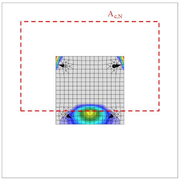
- Ac,N – aire projetée réelle du cône de rupture de l'élément de fixation, limitée par les éléments de fixation adjacents et les bords de l'élément en béton – Art. 6.2.3.3
- Ac,N0 = scr,N2 – aire projetée de référence d'un élément de fixation isolé avec une distance au bord au moins égale à 1,5 hef – Art. 6.2.3.3
- \( \psi_{s,N} = 0.7 + 0.3 \frac{c}{c_{cr,N}} \le 1 \) – paramètre lié à la distribution des contraintes dans le béton en raison de la proximité de l'élément de fixation avec un bord de l'élément en béton – Art. 6.2.3.4
- \( \psi_{re,N} = 0.5 + \frac{h_{ef}}{200} \le 1 \)– paramètre tenant compte de l'effet d'écaillage de la surface – Art. 6.2.3.5
- \( \psi_{ec,N} = \frac{1}{1+2 e_N / s_{cr,N}} \le 1 \) – paramètre tenant compte de l'excentricité de la résultante des charges dans un groupe d'éléments de fixation – Art. 6.2.3.6
- \( \psi_{M,N} = 2- \frac{2 z}{3 h_{ef}} \ge 1 \) – paramètre tenant compte de l'effet d'un effort de compression entre la platine et le béton – Art. 6.2.3.7 ; ce paramètre est égal à 1 si c < 1,5 hef ou si le rapport de l'effort de compression (y compris la compression due à la flexion) à la somme des efforts de traction dans les ancrages est inférieur à 0,8
- \item k1 – paramètre ; pour les ancrages coulés en place (type d'ancrage – rondelles) k1 = kcr,N = 8,9 pour le béton fissuré et k1 = kucr,N = 12,7 pour le béton non fissuré ; pour les ancrages post-installés (type d'ancrage – droit) k1 = kcr,N = 7,7 pour le béton fissuré et k1 = kucr,N = 11,0 pour le béton non fissuré
- scr,N = 2 ccr,N = 3 hef – entraxe des éléments de fixation
- ccr,N = 1,5 hef – distance au bord caractéristique
- hef – profondeur d'encastrement effective de l'élément de fixation ; dans le cas d'un élément en béton de faible largeur, l'Art. 6.2.3.8 s'applique et\( h'_{ef} = \max \left ( \frac{c_{max}}{c_{cr,N}}h_{ef}; \, \frac{s_{max}}{s_{cr,N}}h_{ef} \right ) \)
- z – bras de levier interne
- c – distance minimale au bord
L'aire du cône d'éclatement du béton pour un groupe d'ancrages sollicités en traction formant un cône de béton commun, Ac,N, est représentée par un trait pointillé rouge.
Conformément à l'Art. 6.2.8, l'armature complémentaire peut être utilisée pour transmettre les forces provoquant la rupture par cône de béton. Ce ferraillage doit être dimensionné conformément à l'AS 3600.
Rupture par arrachement
La rupture par arrachement est vérifiée pour les éléments de fixation à tête coulés en place (type d'ancrage – rondelle) conformément à la SA TS 101:2015 – Art. 6.2.3 :
\[ ϕ_{Mc} N_{Rk,p} = k_1 A_h f'_c \]
- ϕMc – facteur de capacité pour les modes de rupture des ancrages liés au béton, modifiable dans la configuration normative ; la valeur recommandée est 1/1,5 (Tableau 3.2.4)
- k1 – paramètre lié à l'état du béton ; pour le béton fissuré k1 = 8,0, pour le béton non fissuré k1 = 11,2
- Ah – aire de la tête portante de l'élément de fixation ; pour une rondelle circulaire \( A_h = \frac{\pi}{4} \left ( d_h^2 - d^2 \right \)$, pour une rondelle rectangulaire \( A_h = a_{wp}^2 - \frac{\pi}{4} d^2 \)
- dh ≤ 6 th + d – diamètre de la tête de l'élément de fixation
- th – épaisseur de la tête de l'élément de fixation à tête
- d – diamètre de la tige de l'élément de fixation
- awp – longueur du côté de la rondelle rectangulaire
- f'c – résistance caractéristique à la compression du béton
La rupture par arrachement pour les ancrages autres que les ancrages à tête coulés en place n'est pas calculée et la résistance doit être garantie par un fabricant ou déterminée par des essais et une évaluation conformément à l'Annexe A.
Ni la résistance à la rupture par fendage lors de la mise en œuvre (Art. 6.2.6.1) ni celle due aux charges (Art. 6.2.6.2) n'est fournie et doit être garantie par un fabricant ou déterminée par des essais et une évaluation conformément à l'Annexe A.
Rupture par éclatement latéral
La rupture par éclatement latéral est vérifiée pour les ancrages à tête (type d'ancrage – rondelle) avec une distance au bord c ≤ 0,5 hef conformément à l'Art. 6.2.7. Les ancrages sont traités comme un groupe si leur entraxe près du bord est s ≤ 4 c1. Les ancrages à contre-dépouille peuvent être vérifiés de la même manière, mais la valeur de Ah est inconnue dans le logiciel. La rupture par éclatement latéral des ancrages à contre-dépouille peut être déterminée en sélectionnant une rondelle avec la dimension correspondante.
\[ ϕ_{Mc} N_{Rk,cb} = ϕ_{Mc} N_{Rk,cb}^0 \frac{A_{c,Nb}}{A_{c,Nb}^0} \psi_{s,Nb} \psi_{g,Nb} \psi_{ec,Nb} \]
où :
- ϕMc – facteur de capacité pour les modes de rupture des ancrages liés au béton, modifiable dans la configuration normative ; la valeur recommandée est 1/1,5 (Tableau 3.2.4)
- \( N_{Rk,cb}^0 = k_5 c_1 \sqrt{A_h} \sqrt{f'_c} \) – résistance caractéristique d'un élément de fixation isolé, éloigné des effets des éléments de fixation adjacents et des bords de l'élément en béton – Art. 6.2.7.2
- Ac,Nb – aire projetée réelle pour l'élément de fixation, limitée par les bords de l'élément en béton (c2 ≤ 2 c1), la présence d'éléments de fixation adjacents (s ≤ 4 c1) ou l'épaisseur de l'élément – Art. 6.2.7.3
- Ac,Nb0 = (4 c1)2 – aire projetée de référence d'un élément de fixation isolé avec une distance au bord égale à c1 – Art. 6.2.7.3
- \( \psi_{s,Nb} = 0.7+0.3 \frac{c_2}{2 c_1} \le 1 \) – paramètre tenant compte de la perturbation des contraintes dans le béton due à la proximité de l'élément de fixation avec un angle de l'élément en béton – Art. 6.2.7.4
- \( \psi_{g,Nb} = \sqrt{n} + (1-\sqrt{n}) \frac{s_2}{4c_1} \ge 1 \) – paramètre tenant compte de l'effet de groupe – Art. 6.2.7.5
- \( \psi_{ec,Nb} = \frac{1}{1+2 e_N / s_{cr,Nb}} \le 1 \) – paramètre tenant compte de l'excentricité du chargement sur un groupe d'éléments de fixation – Art. 6.2.7.6
- k5 – paramètre lié à l'état du béton ; pour le béton fissuré k5 = 8,7, pour le béton non fissuré k5 = 12,2
- c1 – distance au bord de l'élément de fixation dans la direction 1 vers le bord le plus proche
- c2 – distance au bord de l'élément de fixation perpendiculairement à la direction 1, qui est la plus petite distance au bord dans un élément étroit avec plusieurs distances au bord
- Ah – aire de la tête portante de l'élément de fixation ; pour une rondelle circulaire \( A_h = \frac{\pi}{4} \left ( d_h^2 - d^2 \right \), pour une rondelle rectangulaire \( A_h = a_{wp}^2 - \frac{\pi}{4} d^2 \)
- f'c – résistance caractéristique à la compression du béton
- n – nombre d'éléments de fixation dans une rangée parallèle au bord de l'élément en béton
- s2 – entraxe des éléments de fixation dans un groupe perpendiculairement à la direction 1
- scr,Nb = 4 c1 – entraxe requis pour qu'un élément de fixation développe sa résistance caractéristique en traction vis-à-vis de la rupture par éclatement latéral
Rupture de l'acier en cisaillement
La rupture de l'acier en cisaillement est déterminée conformément à l'Art. 7.2.2. On suppose que l'ancrage est constitué d'une tige filetée avec les mêmes propriétés matérielles que les boulons.
Effort tranchant sans bras de levier
L'effort tranchant sans bras de levier est supposé lorsque l'option déport – direct est sélectionnée. On suppose que les éléments de fixation sont en acier ductile et que le facteur k7 = 1. Chaque élément de fixation est vérifié séparément. La résistance est déterminée conformément à l'AS 5216 – Art. 7.2.2.2 et à l'AS 4100 – Art. 9.2.2.1 :
\[ ϕ_{Ms} V_{Rk,s} = ϕ_{Ms} 0.62 f_{uf} A \]
où :
- \( ϕ_{Ms} = f_{yf} / f_{uf} \le 0.8 \) lorsque fuf ≤ 800 MPa et fyf / fuf ≤ 0,8 ; ϕMs = 2/3 sinon – facteur de capacité pour la rupture de l'acier en cisaillement (Tableau 3.2.4)
- fuf – résistance minimale à la traction du boulon telle que spécifiée dans l'AS 4100 Tableau 9.2.1
- A – aire d'un boulon égale soit à Ac soit à Ao, qui sont respectivement l'aire de la section au diamètre minimal du boulon telle que définie dans l'AS 1275 ou l'aire nominale de la tige lisse du boulon
Pour les éléments de fixation avec hef / d < 5 dans un béton ayant f'c < 20 MPa, VRk,s est multiplié par un facteur égal à 0,8.
Effort tranchant avec bras de levier
La résistance au cisaillement de l'acier avec bras de levier est calculée conformément à l'Art. 7.2.2.3 :
\[ ϕ_{Ms} V_{Rk,s,M} = ϕ_{Ms} \frac{\alpha_M M_{Rk,s}}{l_a} \]
où :
- \( ϕ_{Ms} = f_{yf} / f_{uf} \le 0.8 \) lorsque fuf ≤ 800 MPa et fyf / fuf ≤ 0,8 ; ϕMs = 2/3 sinon – facteur de capacité pour la rupture de l'acier en cisaillement (Tableau 3.2.4)
- αM = 2 – paramètre tenant compte du degré d'encastrement ; la platine est supposée empêchée de tourner – Art. 4.2.2.4
- \( M_{Rk,s} = M_{Rk,s}^0 \left ( 1- \frac{N^*}{ϕ_{Ms} N_{Rk,s}} \right ) \) – résistance caractéristique à la flexion de l'élément de fixation influencée par l'effort axial
- la = a3 + e1 – longueur du bras de levier
- a3 = 0,5 d – distance entre le point supposé d'encastrement de l'élément de fixation sollicité en cisaillement et la surface du béton
- e1 = tg + tfix / 2 – excentricité de l'effort tranchant appliqué par rapport à la surface du béton, en négligeant l'épaisseur d'un calage ou d'un mortier de nivellement
- tg – épaisseur de la couche de mortier
- tfix – épaisseur de la platine de base
- d – diamètre nominal de l'élément de fixation
- N* – effort de traction de calcul
- ϕMs NRk,s – résistance en traction d'un élément de fixation à la rupture de l'acier
- MRk,s0 = 1,2 Wel fuf – résistance caractéristique à la flexion de l'élément de fixation – ETAG 001 – Annexe C
- Wel = π d3 / 32 – module d'inertie élastique de l'élément de fixation ; le diamètre réduit au niveau des filets, \( d_s = \sqrt{\frac{4 A_s}{\pi}} \), est utilisé à la place du diamètre nominal, d, si le plan de cisaillement dans le filet est sélectionné
Rupture du béton en bord
La rupture du béton en bord est vérifiée conformément à l'Art. 7.2.3. Si les cônes de béton des éléments de fixation se recoupent, ils sont vérifiés en tant que groupe. Les bords dans la direction de l'effort tranchant sont vérifiés. L'ensemble des charges sur une platine de base est supposé être transmis par un élément de fixation proche du bord vérifié.
\[ ϕ_{Mc} V_{Rk,c} = ϕ_{Mc} V_{Rk,c}^0 \frac{A_{c,V}}{A_{c,V}^0} \psi_{s,V} \psi_{h,V} \psi_{ec,V} \psi_{\alpha,V} \psi_{re,V} \]
où :
- ϕMc – facteur de capacité pour les modes de rupture des ancrages liés au béton, modifiable dans la configuration normative ; la valeur recommandée est 1/1,5 (Tableau 3.2.4)
- \( V_{Rk,c}^0 = k_9 d^{\alpha} l_f^{\beta} \sqrt{f'_c} c_1^{1.5} \) – valeur initiale de la résistance caractéristique au cisaillement de l'élément de fixation – Art. 7.2.3.2
- Ac,V – aire réelle du corps d'éclatement idéalisé du béton – Art. 7.2.3.3
- Ac,V0 = 4,5 c12 – aire projetée de référence du cône de rupture – Art. 7.2.3.3
- \( psi_{s,V} = 0.7 + 0.3 \frac{c_2}{1.5 c_1} \le 1 \) – paramètre tenant compte de la perturbation de la distribution des contraintes dans l'élément en béton – Art. 7.2.3.4
- \( \psi_{h,V} = \left ( \frac{1.5 c_1}{h} \right ) ^{0.5} \ge 1 \) – paramètre tenant compte de l'influence de l'épaisseur de l'élément – Art. 7.2.3.5
- \( \psi_{ec,V} = \frac{1}{1+2 e_V / (3c_1)} \le 1 \) – paramètre tenant compte de l'excentricité de la résultante des charges dans un groupe d'éléments de fixation – Art. 7.2.3.6
- \( \psi_{\alpha,V} = \sqrt{\frac{1}{(\cos \alpha_V)^2 + (0.5 \sin \alpha_V)^2}} \ge 1 \) – paramètre tenant compte de l'angle de la charge appliquée – Art. 7.2.3.7
- ψre,V = 1 – paramètre tenant compte de l'effet d'écaillage de la surface – Art. 7.2.3.8 ; aucun ferraillage de bord ni étrier n'est supposé
- k9 – paramètre tenant compte de l'état du béton ; pour le béton fissuré k9 = 1,7, pour le béton non fissuré k9 = 2,4
- d – diamètre nominal de l'élément de fixation
- \( \alpha = 0.1 \left ( \frac{l_f}{c_1} \right ) ^{0.5} \)
- \( \beta = 0.1 \left ( \frac{d}{c_1} \right ) ^{0.2} \)
- lf = hef ≤ 12 d où d ≤ 24 mm ; lf = hef ≤ max (8 d, 300 mm) où d > 24 mm – paramètre lié à la longueur de l'élément de fixation
- f'c – résistance caractéristique à la compression sur cylindre du béton à 28 jours
- c1 – distance au bord de l'élément de fixation vers le bord étudié ; conformément à l'Art. 7.2.3.9, pour un élément étroit, c2,max < 1,5 c1 également considéré comme mince, h < 1,5 c1, c'1 est utilisé dans les équations précédentes à la place de c1 ; la valeur réduite c'1 = max (c2,max / 1,5, h/ 1,5, sc,max / 3)
- c2 – la plus petite distance au bord de l'élément de fixation dans la direction perpendiculaire au bord étudié
- h – épaisseur de l'élément en béton
- eV – excentricité de la résultante de l'effort tranchant agissant sur un groupe d'éléments de fixation par rapport au centre de gravité des éléments de fixation sollicités en cisaillement
- αV – angle entre la charge appliquée à l'élément de fixation ou au groupe d'éléments de fixation et la direction perpendiculaire au bord libre considéré, 0° < αV < 90°
- hef – profondeur d'encastrement effective de l'élément de fixation
Conformément à l'Art. 6.2.8, l'armature complémentaire peut être utilisée pour transmettre les forces provoquant la rupture du béton en bord et/ou la rupture par poinçonnement du béton. Ce ferraillage doit être dimensionné conformément à l'AS 3600.
Rupture par poinçonnement du béton
La rupture par poinçonnement du béton est vérifiée conformément à l'Art. 7.2.4. Tous les ancrages d'une platine de base sont supposés sollicités en cisaillement et la résistance à l'éclatement du béton, NRk,c, utilisée dans le calcul, est calculée en supposant que tous les ancrages sont sollicités en traction sans excentricité. Aucune armature complémentaire n'est supposée.
\[ ϕ_{Mc} V_{Rk,cp} = ϕ_{Mc} k_8 N_{Rk,c} \]
où :
- ϕMc – facteur de capacité pour les modes de rupture des ancrages liés au béton, modifiable dans la configuration normative ; la valeur recommandée est 1/1,5 (Tableau 3.2.4)
- k8 – paramètre publié dans le Rapport d'Évaluation, conformément à l'ETAG 001 – Annexe C ; pour hef < 60 mm, k8 = 1 et pour hef ≥ 60 mm, k8 = 2
- NRk,c – résistance caractéristique du cône de béton pour un élément de fixation isolé ou un élément de fixation dans un groupe
Chargement combiné traction et cisaillement
La résistance d'un élément de fixation sollicité par un chargement combiné de traction et de cisaillement est déterminée conformément au Chapitre 8.
Rupture de l'acier
L'évaluation du comportement sous chargement combiné de traction et de cisaillement de l'élément de fixation est basée sur l'AS 4100 :
\[ \left ( \frac{N^*}{ϕ_{Ms} N_{Rk,s}} \right ) ^2 + \left ( \frac{V^*}{ϕ_{Ms} V_{Rk,s}} \right ) ^2 \le 1.0 \]
Rupture du béton
Les modes de rupture autres que la rupture de l'acier sont vérifiés conformément à l'Art. 8.2.1 :
\[ \left ( \frac{N^*}{ϕ_{Mc} N_{Rk,i}} \right ) ^{1.5} + \left ( \frac{V^*}{ϕ_{Mc} V_{Rk,i}} \right ) ^{1.5} \le 1.0 \]
où :
- N* – effort de traction de calcul appliqué à un élément de fixation isolé ou à un groupe
- V* – effort tranchant de calcul appliqué à un élément de fixation isolé ou à un groupe
- NRk,i – résistance caractéristique en traction de l'élément de fixation ou du groupe pour le mode de rupture « i »
- VRk,i – résistance caractéristique au cisaillement de l'élément de fixation ou du groupe pour le mode de rupture « i »
- \( ϕ_{Ms} = \frac{5 f_{yf}}{6 f_{uf}} \) – facteur de capacité pour la rupture de l'acier en traction (Tableau 3.2.4)
- ϕMs = fyf / fuf ≤ 0,8 lorsque fuf ≤ 800 MPa et fyf / fuf ≤ 0,8 ; ϕMs = 2/3 sinon – facteur de capacité pour la rupture de l'acier en cisaillement (Tableau 3.2.4)
- ϕMc – facteur de capacité pour les modes de rupture des ancrages liés au béton, modifiable dans la configuration normative ; la valeur recommandée est 1/1,5 (Tableau 3.2.4)
Ancrages avec déport
Les ancrages avec déport sont dimensionnés comme des éléments de type poutre conformément à l'AS 4100 avec les facteurs de capacité des boulons. La longueur supposée de l'élément est la somme de la hauteur du jeu, de la moitié du diamètre nominal et de la moitié de l'épaisseur de la platine de base. Les ancrages avec déport sont généralement vérifiés comme une phase de construction avant le scellement.
Résistance à la flexion
La résistance à la flexion est déterminée conformément à l'AS 4100, Art. 5.1.
M* ≤ ϕ Ms
où :
- M* – moment fléchissant agissant sur l'ancrage déterminé par la méthode des éléments finis
- ϕ = 0,8 – facteur de capacité pour les boulons
- Ms = fy Ze – résistance de la section à la flexion
- fy – limite d'élasticité de l'ancrage
- Ze = min {S, 1,5 · Z} – module d'inertie effectif – Art. 5.2.3
- \( S = \frac{d^3}{6} \) – module d'inertie plastique ; si le plan de cisaillement dans le filet est sélectionné, le diamètre nominal d est remplacé par le diamètre réduit au niveau des filets, ds
- \( Z = \frac{1}{32} \pi d^3 \) – module d'inertie élastique ; si le plan de cisaillement dans le filet est sélectionné, le diamètre nominal d est remplacé par le diamètre réduit au niveau des filets, ds
Résistance au cisaillement
La résistance au cisaillement est déterminée conformément à l'AS 4100, Art. 5.11.
V* ≤ ϕ Vw
où :
- V* – effort tranchant de calcul
- ϕ = 0,8 – facteur de capacité pour les boulons
- Vw = 0,6 fy Aw – résistance nominale au cisaillement par plastification – Art. 5.11.4
- fy – limite d'élasticité de l'ancrage
- Aw = 0,844 As – aire de cisaillement
- As – aire de la section résistante en traction d'un boulon telle que définie dans l'AS 1275
Résistance à la compression axiale
La résistance à la compression axiale est déterminée conformément à l'AS 4100, Art. 6. Le flambement est pris en compte conformément à l'Art. 6.3 :
N* ≤ ϕ Nc
où :
- N* – effort de compression de calcul
- ϕ = 0,8 – facteur de capacité pour les boulons
- Nc = αc Ns ≤ Ns – résistance nominale de l'élément – Art. 6.3.3
- Ns = kf As fy – résistance nominale de la section – Art. 6.2
- fy – limite d'élasticité de l'ancrage
- le = ke l – longueur efficace – Art. 6.3.2
- ke = 2 – facteur de longueur efficace de l'élément ; on suppose de manière conservative que l'ancrage est encastré en bas et articulé en haut en tant qu'élément à déversement libre
- l = lgap + d / 2 + tp / 2 – longueur supposée de l'élément
- lgap – hauteur du jeu
- d – diamètre nominal du boulon
- tp – épaisseur de la platine de base
- \( \alpha_c = \xi \left \{ 1 - \sqrt{1- \left ( \frac{90}{\xi \lambda} \right )^2 } \right \} \) – facteur de réduction d'élancement de l'élément comprimé – Art. 6.3.3
- \( \xi = \frac{\left( \frac{\lambda}{90} \right)^2 + 1 + \eta}{2 \left( \frac{\lambda}{90} \right)^2} \) – facteur de l'élément comprimé – Art. 6.3.3
- \( \lambda = \lambda_n + \alpha_a \alpha_b \) – élancement – Art. 6.3.3
- \( \eta = 0.00326 (\lambda-13.5) \) – facteur d'imperfection de l'élément comprimé – Art. 6.3.3
- \( \lambda_n = \frac{l_e}{r} \sqrt{k_f} \sqrt{\frac{f_y}{250}} \) – élancement modifié de l'élément comprimé – Art. 6.3.3
- kf = 1 – facteur de forme – Art. 6.2.2
- \( r = \sqrt{\frac{I_s}{A_s}} \) – rayon de giration
- \( I_s = \frac{1}{64} \pi d_s^4 \) – moment d'inertie
- As – aire de la section résistante en traction d'un boulon telle que définie dans l'AS 1275
- \( d_s = \sqrt{\frac{4 A_s}{\pi}} \) – diamètre réduit au niveau des filets
- \( \alpha_a = \frac{2100 (\lambda_n - 13.5)}{\lambda_n^2 - 15.3 \lambda_n + 2050} \) – facteur de l'élément comprimé – Art. 6.3.3
- αb = 0,5 – constante de section de l'élément comprimé - Tableau 6.3.3
Résistance à la traction axiale
La résistance à la traction axiale est déterminée conformément à l'AS 4100, Art. 7 :
N* ≤ ϕ Nt
où :
- N* – effort de traction de calcul
- ϕ = 0,8 – facteur de capacité pour les boulons
- Nt = As fy – résistance nominale de la section d'un boulon en traction – Art. 7.2
- As – aire de la section résistante en traction d'un boulon telle que spécifiée dans l'AS 1275
- fy – limite d'élasticité de l'ancrage
Interaction des sollicitations
Si un ancrage avec déport est sollicité par un effort tranchant et un effort de compression, la vérification de l'interaction des sollicitations est effectuée :
\[ \frac{N^*}{\phi N_c} + \frac{M^*}{\phi M_s} \le 1 \]
où :
- N* – effort de compression de calcul
- ϕ = 0,8 – facteur de capacité pour les boulons
- Nc – résistance à la compression
- M* – moment fléchissant de calcul dû au cisaillement sur un bras de levier
- Ms – résistance à la flexion
De plus, les vérifications de la rupture de l'acier en cisaillement et des ruptures du béton en cisaillement (rupture du béton en bord, rupture par poinçonnement du béton) sont effectuées.
Si un ancrage avec déport est sollicité par un effort tranchant et un effort de traction, la vérification de l'interaction des sollicitations est effectuée :
\[ \frac{N_{tf}^*}{\phi N_{t}} + \frac{M^*}{\phi M_s} \le 1 \]
où :
- N*tf – effort de traction de calcul
- ϕ = 0,8 – facteur de capacité pour les boulons
- Nt – résistance en traction
- M* – moment fléchissant de calcul dû au cisaillement sur un bras de levier
- Ms – résistance à la flexion
De plus, les vérifications de la rupture de l'acier en cisaillement et des ruptures du béton dues à la traction et au cisaillement sont effectuées.
Détail des boulons, soudures et ancrages selon les normes australiennes
Boulons
Espacement minimal (distance entre les centres des trous de boulons) ne doit pas être inférieur à 2,5 fois le diamètre nominal du boulon. La valeur est recommandée dans la Clause 9.5.1 et est modifiable dans la configuration du code.
Distance minimale au bord (distance entre le centre du trou de boulon et le bord de la plaque) ne doit pas être inférieure à 1,25 fois le diamètre nominal du boulon. La valeur est recommandée dans la Clause 9.5.2 pour les bords laminés et peut être modifiée dans la configuration du code.
Soudures
La taille minimale d'une soudure d'angle est vérifiée conformément à la Clause 9.6.3.2 et doit être la valeur la plus faible entre l'épaisseur de la partie la plus mince assemblée et la valeur du tableau suivant :
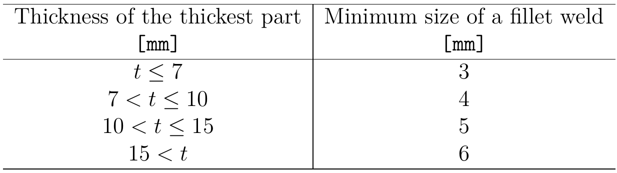
La taille de la soudure est supposée égale à \( \sqrt{2} \) fois l'épaisseur de la gorge de soudure.
Ancrages
L'espacement minimal entre les ancrages doit être s ≥ 4d où d est le diamètre nominal de l'ancrage. Le facteur 4 est modifiable dans la configuration du code.
La distance minimale au bord suit les règles applicables aux boulons, c'est-à-dire qu'elle ne doit pas être inférieure à 1,25 fois le diamètre nominal du boulon. La valeur est recommandée dans la Clause 9.5.2 pour les bords laminés et peut être modifiée dans la configuration du code.
Classement des assemblages selon les normes australiennes
Les assemblages sont classés selon leur rigidité en :
- Rigide – assemblages avec une variation négligeable des angles initiaux entre les éléments,
- Semi-rigide – assemblages supposés avoir la capacité de fournir un degré de retenue en flexion fiable et connu,
- Articulé – assemblages qui ne développent pas de moments fléchissants.
La norme australienne AS 4100, Cl. 4.2 ne fournit pas de limites exactes, aussi les assemblages sont classés selon le commentaire de l'AISC 360-16, Cl. B3.4.
- Rigide – \( \frac{S_{j,ini} L_b}{E I_b} \ge 20 \)
- Semi-rigide – \( 2 < \frac{S_{j,ini} L_b}{E I_b} < 20 \)
- Articulé – \( \frac{S_{j,ini} L_b}{E I_b} \le 2 \)
où :
- Sj,ini – rigidité initiale de l'assemblage ; la rigidité de l'assemblage est supposée linéaire jusqu'aux 2/3 de Mj,Rd
- Lb – longueur théorique de l'élément analysé
- E – module d'élasticité de Young
- Ib – moment d'inertie de l'élément analysé
- Mj,Rd – résistance de calcul au moment de l'assemblage
Dimensionnement en capacité selon les normes australiennes
Le dimensionnement en capacité fait partie de la vérification sismique et garantit que l'assemblage possède une capacité de déformation suffisante.
L'objectif du dimensionnement en capacité est de confirmer qu'un bâtiment présente un comportement ductile contrôlé afin d'éviter l'effondrement lors d'un séisme de niveau de calcul. Le dimensionnement en capacité est absent de la norme australienne, c'est pourquoi la norme néo-zélandaise est utilisée à la place. La rotule plastique est supposée apparaître dans l'élément dissipatif, et tous les éléments non dissipatifs de l'assemblage doivent être capables de transférer en toute sécurité les efforts dus à la plastification de l'élément dissipatif. L'élément dissipatif est généralement une poutre dans un portique à nœuds rigides, mais il peut également s'agir, par exemple, d'une platine d'extrémité. Le coefficient de sécurité n'est pas appliqué aux éléments dissipatifs. La limite d'élasticité de l'élément dissipatif est calculée comme Fy,max = 0.9 ϕos ϕomfy, où :
- ϕos – facteur d'écrouissage ; les valeurs recommandées sont ϕos = 1.15 pour une poutre dans un portique à nœuds rigides, γsh = 1.0 sinon ; modifiable dans l'opération
- ϕom – facteur de surrésistance – EN 1998-1, Art. 6.2 ; la valeur recommandée est ϕom = 1.3 ; modifiable dans les matériaux
Le diagramme de matériau est modifié conformément à la figure suivante :
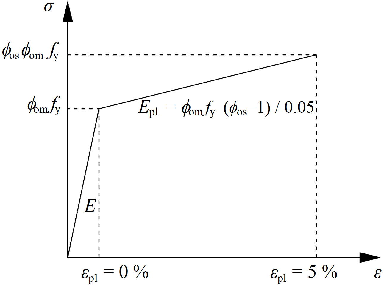
La résistance accrue de l'élément dissipatif permet l'introduction de charges provoquant l'apparition de la rotule plastique dans l'élément dissipatif. Dans le cas d'un portique à nœuds rigides avec une poutre comme élément dissipatif, la poutre doit être chargée par My = fy,maxWpl,y et l'effort tranchant correspondant Vz = –2 My / Lh, où :
- fy – limite d'élasticité caractéristique
- Wpl,y – module plastique de la section
- Lh – distance entre les rotules plastiques sur la poutre
Dans le cas d'un assemblage asymétrique, la poutre doit être chargée par des moments fléchissants positifs et négatifs ainsi que par leurs efforts tranchants correspondants.
Les plaques des éléments dissipatifs sont exclues de la vérification normative.