Analyse sismique dans IDEA StatiCa Connection
Introduction
Lors de la conception de la structure pour résister à la combinaison de charges sismiques, l'ingénieur doit choisir un concept :
- Comportement structurel peu dissipatif
- q = 1 à 2 (classe de section 4 → q = 1)
- Aucune exigence particulière pour les structures en acier
- Classe de ductilité faible (DCL)
- Comportement structurel dissipatif
- q ≤ 4 – Classe de ductilité moyenne (DCM), classe de section 1, 2
- q > 4 – Classe de ductilité haute (DCH), classe de section 1
Pour un comportement structurel peu dissipatif, aucune exigence particulière n'est nécessaire et les vérifications normatives habituelles des assemblages sont requises. Cependant, pour des charges sismiques élevées, concevoir une structure restant en état élastique est irréalisable, et un comportement structurel dissipatif est nécessaire. L'analyse par capacité de résistance des éléments (Member Capacity Design) dans IDEA StatiCa Connection est destinée à ce type de comportement.
Les types structurels possibles de systèmes de résistance sismique autorisés dans EN 1998-1 sont :
- Portiques à nœuds rigides (MRF)
- rotules plastiques aux extrémités des poutres ou dans les assemblages des poutres aux poteaux
- les rotules plastiques peuvent également se former :
- à la base du poteau
- au sommet du poteau au dernier niveau
- Portiques à contreventements concentriques (CBF) :
- les zones dissipatives sont situées dans les diagonales en traction
- Portiques à contreventements excentriques (EBF) :
- zones dissipatives dans les liens sismiques, principalement dans les poutres
- Structures en pendule inversé
- Structures en acier associées à des noyaux en béton ou des voiles en béton
- Portiques mixtes composés de portiques à nœuds rigides combinés avec des portiques contreventés
- Le MRF contribue > 25 % à la résistance et à la rigidité totales
- Portiques à nœuds rigides combinés avec des remplissages en béton armé
Détermination des cas de charges sismiques
Les efforts intérieurs pour la combinaison de charges sismiques peuvent être déterminés par l'une des méthodes suivantes d'analyse sismique structurelle :
- Méthode des forces latérales
- Analyse modale par spectre de réponse linéaire
- Analyse statique non linéaire (pushover)
- Analyse dynamique non linéaire par intégration temporelle
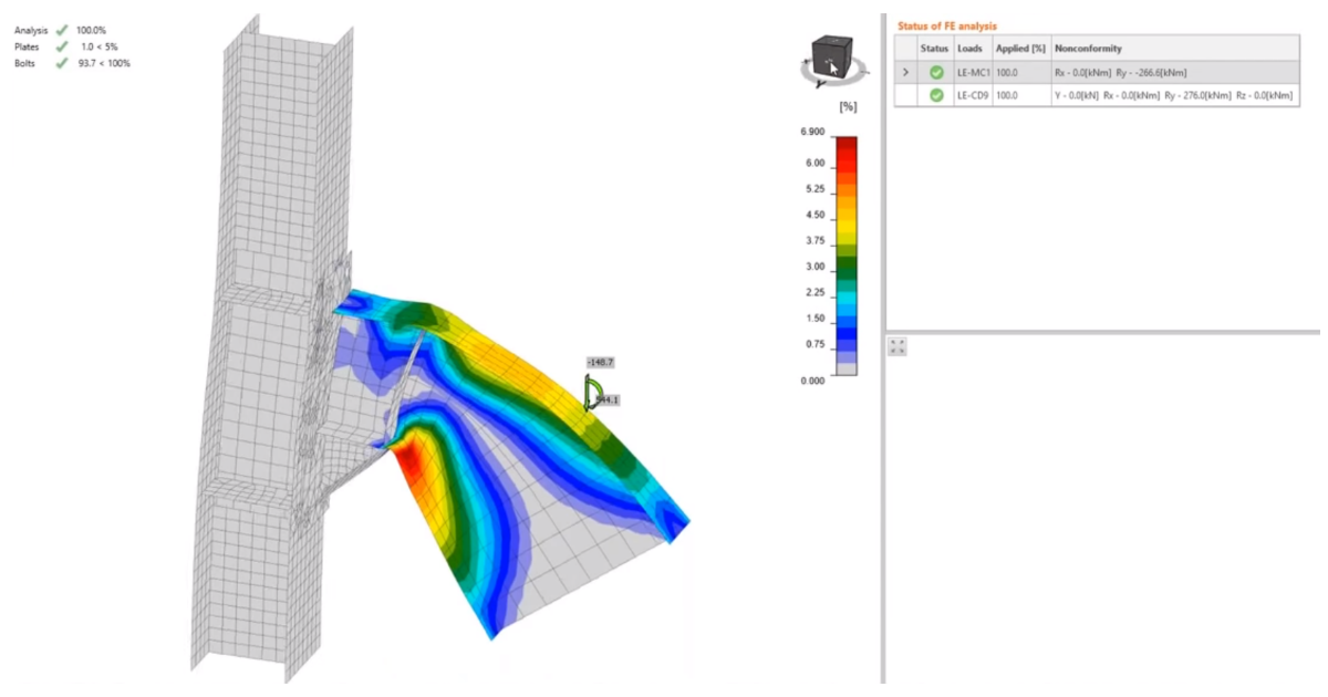
L'utilisation de l'analyse modale par spectre de réponse linéaire entraîne une « perte de signe » des efforts intérieurs en raison de la méthode de la racine carrée de la somme des carrés (SRSS). Les signes doivent être retrouvés par la méthode des forces latérales – l'assemblage dans IDEA StatiCa doit être en équilibre. Les charges sismiques sont dans la combinaison de charges accidentelles et la structure est analysée. Les assemblages sont vérifiés à l'aide de l'analyse standard Contrainte-déformation (EPS) dans IDEA StatiCa Connection.
De plus, les éléments non dissipatifs doivent être capables de transférer, sans déformations significatives, les efforts nécessaires à la formation des rotules plastiques dans les éléments dissipatifs. Cette vérification supplémentaire est effectuée dans l'analyse par capacité de résistance des éléments (MC).
Conception par capacité de résistance
L'objectif de la conception par capacité de résistance est de confirmer qu'un bâtiment présente un comportement ductile contrôlé afin d'éviter l'effondrement lors d'un séisme de niveau de calcul. Cela implique de concevoir la structure pour permettre une rupture ductile en des emplacements clés et prévisibles au sein de la structure, et d'empêcher d'autres types de rupture de se produire à proximité de ces emplacements ou ailleurs dans la structure.
En d'autres termes, dans une structure contenant à la fois des éléments fragiles et ductiles, la conception par capacité de résistance est une méthode permettant de conférer à la structure une caractéristique globalement ductile.
Certains éléments sont considérés comme dissipatifs et d'autres comme non dissipatifs. Les assemblages sont généralement non dissipatifs, mais peuvent dans certains cas être dissipatifs. Les éléments dissipatifs sont censés subir des déformations plastiques importantes lors du cas de charge sismique ; l'énergie sismique peut être dissipée lors de ces déformations, et la charge sismique est donc significativement réduite. En revanche, les éléments dissipatifs doivent être capables de résister aux déformations cycliques sans fissuration, et tous les éléments non dissipatifs doivent être capables de transférer les charges induites par les éléments dissipatifs. Pour assurer la formation de la rotule plastique dans l'élément dissipatif, la limite d'élasticité probable est utilisée à la place de la limite d'élasticité nominale, et parfois, notamment pour les poutres dans les MRF, l'écrouissage est également pris en compte. Ainsi, la résistance des éléments dissipatifs est prise comme :
\(f_{y,max} = \gamma_{sh} \cdot \gamma_{ov} \cdot f_y \) (EN)
\(F_{y,max}= C_{pr} \cdot R_y \cdot F_y \) (AISC)
où :
- γsh – facteur d'écrouissage, égal à 1,1 dans EN 1998-1 et 1,2 dans EN 1993-1-8 ; la valeur 1,2 est recommandée dans les manuels ECCS car elle correspond mieux aux nuances d'acier utilisées pour les applications sismiques ; modifiable au niveau de la fonction d'élément dissipatif
- γov – facteur de sur-résistance, valeur recommandée 1,25 ; modifiable dans les matériaux
- \(C_{pr} = \frac{F_y + F_u}{2 \cdot F_y}\) – facteur d'écrouissage – AISC 358-16 (2.4-2) ; peut être activé ou désactivé au niveau de la fonction d'élément dissipatif
- Ry – rapport entre la limite d'élasticité probable et la limite d'élasticité minimale – AISC 341-16 – Tableau A3.1 ; modifiable dans les matériaux
La résistance ultime (en traction) est également modifiée pour les éléments sélectionnés comme dissipatifs :
\(f_{u,max}= \gamma_ov \cdot f_u \) (EN)
\(F_{u,max} = R_t \cdot F_u \) (AISC)
où :
- γov – facteur de sur-résistance, valeur recommandée 1,25 ; modifiable dans les matériaux
- Ru – rapport entre la résistance en traction probable et la résistance en traction minimale – AISC 341-16 – Tableau A3.1 ; modifiable dans les matériaux
Tous les facteurs sont modifiables, offrant à l'utilisateur une grande liberté. De plus, plusieurs fonctions de sur-résistance peuvent être créées avec des propriétés variables, mais une plaque ne peut être sélectionnée qu'une seule fois. Le facteur d'écrouissage n'est généralement pas utilisé (égal à 1) pour l'analyse des portiques contreventés. Notez que les facteurs de sécurité (résistance/capacité) ne sont pas utilisés pour les éléments dissipatifs (éléments ou plaques avec fonction de sur-résistance appliquée).
Étude de cas : Portiques à nœuds rigides
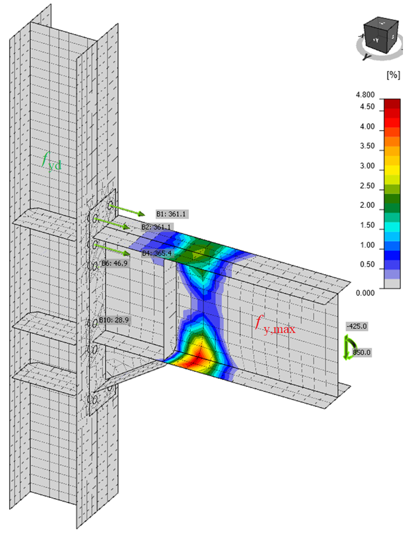
En général, la poutre est un élément dissipatif dans lequel la rotule plastique est censée se former, et l'assemblage et le poteau sont des éléments non dissipatifs qui doivent rester sans déformations significatives. La poutre est chargée par l'effort nécessaire à la formation de la rotule plastique dans la poutre avec la limite d'élasticité probable et par l'effort tranchant correspondant :
\[ M_{Ed} = f_{y,max} \cdot W_{pl} \]
\[V_{Ed} = \frac{2M_{Ed}}{L_h} + V_{gravity} \]
où :
- Wpl – module plastique de la section de la poutre
- Lh – distance entre deux rotules plastiques sur la poutre
- Vgravity – effort tranchant dû aux charges gravitaires dans la combinaison sismique
Notez que si un assemblage poutre-poteau double est utilisé, les efforts doivent provenir du même cas de charge avec les directions correctes, par exemple :
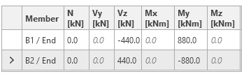
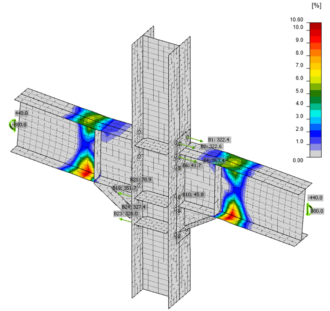
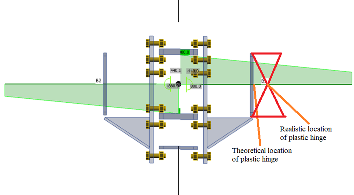
Les efforts tranchants sont généralement appliqués au nœud pour les assemblages rigides. Mais l'effort tranchant appliqué correspondant réduit le moment fléchissant à la rotule plastique. Le moment à la rotule plastique est calculé comme \(M_{Ed} = f_{y,max} \cdot W_{pl}\) et le moment fléchissant My au nœud est augmenté par l'effort tranchant Vz à \( M_y = f_{y,max} \cdot W_{pl} + V_z \cdot s_h \) où sh est la distance entre le nœud et l'emplacement de la rotule plastique. AISC 358 spécifie la valeur sh mais pour la distance entre la face du poteau et la rotule plastique.
Une autre option consiste à définir \(M_y = f_{y,max} \cdot W_{pl} \) et à positionner l'effort tranchant à l'emplacement de la rotule plastique prévue (Modèle > Forces en > Position).
D'autres éléments non dissipatifs peuvent être connectés à l'assemblage. Ces éléments doivent être chargés par les charges gravitaires issues de la combinaison de charges sismiques accidentelles.
Détails constructifs
Les règles de détail spécifiées dans les normes applicables ne sont pas vérifiées dans IDEA StatiCa Connection et doivent être respectées. La résistance à la fatigue oligocyclique de nombreux assemblages résistants aux séismes a été validée par des essais expérimentaux. Les détails de soudure sont particulièrement sensibles à la fissuration par fatigue, et une simple vérification normative des soudures n'est pas suffisante pour les assemblages d'éléments dissipatifs. Des exemples de détails de soudure prescrits dans le projet EQUALJOINTS sont présentés ci-dessous.
Détails de soudure des soudures bout à bout à pleine pénétration des assemblages poutre-poteau à platine d'extrémité raidie et non raidie :
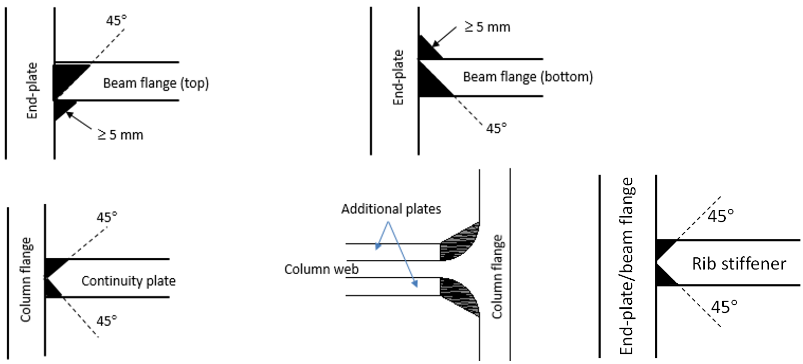
Détails de soudure pour les assemblages à platine d'extrémité avec jarret :

Réduction de section (Dog bone)
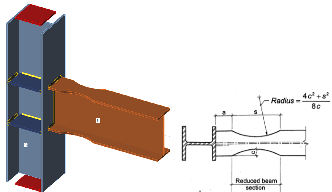
Largeur de semelle de la poutre : bf
Hauteur de la poutre : db
Profondeur maximale de la découpe de la semelle : c = 0.25 bf
Profondeur recommandée de la découpe de la semelle : c = 0.20 bf
Distance entre la face du poteau et le début de la section de poutre réduite : a = 0.6 bf
Longueur sur laquelle la semelle est réduite : s = 0.75 db
La capacité de rotation de l'assemblage
IDEA StatiCa Connection fournit des diagrammes moment-rotation pour tout élément connecté. L'analyse de rigidité donne (entre autres) les résultats suivants :
- Rigidité initiale
- Capacité limite pour 5 % de déformation plastique
- Capacité de rotation pour 15 % de déformation plastique
Tous ces résultats sont importants pour la conception sismique appropriée de l'assemblage. La capacité de rotation (rotation ϕc) est utilisée pour l'évaluation de la ductilité de l'assemblage. La valeur obtenue peut être comparée aux valeurs recommandées dans les normes de calcul.

Résumé
L'assemblage destiné à faire partie d'un système de résistance sismique à comportement structurel dissipatif doit être vérifié vis-à-vis de :
- combinaisons de charges standard (analyse EPS)
- combinaison de charges sismiques accidentelles (analyse EPS)
- charge nécessaire à la formation d'une rotule plastique dans l'élément dissipatif (analyse MC)
Les règles de détail spécifiées par les normes doivent être respectées.
Références :
- EN 1998-1 Chapitre 6 : Règles spécifiques pour les bâtiments en acier
- EN 1993-1-8
- ACI 341-16 https://www.aisc.org/globalassets/aisc/publications/standards/seismic-provisions-for-structural-steel-buildings-ansi-aisc-341-16.pdf
- ACI 358-18 https://www.aisc.org/globalassets/aisc/publications/standards/a358-18w.pdf
- ACI 360-16 https://www.aisc.org/globalassets/aisc/publications/standards/a360-16-spec-and-commentary.pdf
- CSA S16-14