Pandeo global vs. pandeo local. ¿Qué significa?
El código de diseño establece que el análisis de primer orden puede utilizarse para la estructura si el aumento de los esfuerzos internos o momentos relevantes, o cualquier otro cambio en el comportamiento estructural causado por las deformaciones, puede despreciarse.
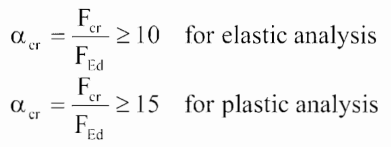
Para evaluar si este aumento puede o no despreciarse, se puede utilizar el factor crítico de pandeo αcr. Podemos despreciar el pandeo global para los elementos, (incluida la unión) en los casos en que el factor de pandeo sea superior a 15 (en caso de diseño plástico) o superior a 10 (en caso de que la tensión en las placas esté en la rama elástica).
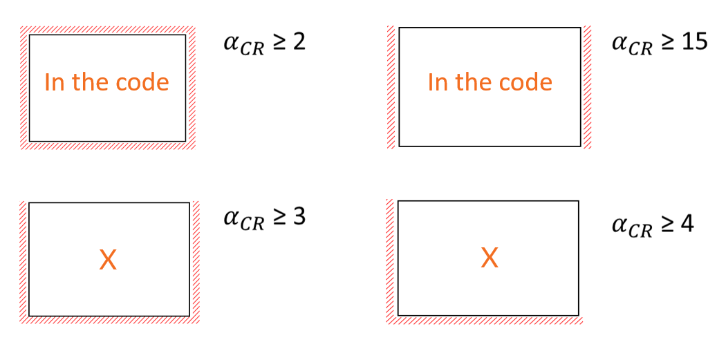
El pandeo local se aplica a placas individuales (rigidizadores, alma del pilar), y los factores de pandeo límite correspondientes se establecen según los códigos de diseño y los experimentos de investigación. Se considera que los efectos del pandeo local son despreciables cuando el factor de pandeo es:
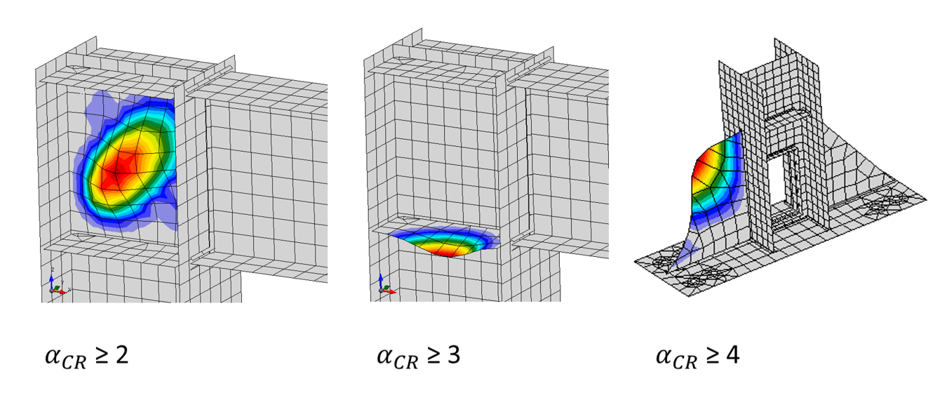
- ≥ 2 - en el caso de una placa apoyada en 4 lados
- ≥ 3 - en el caso de una placa apoyada en 3 lados
- ≥ 4 - en el caso de una placa apoyada en 2 lados (adyacentes)
- ≥ 15 - en el caso de una placa apoyada en 2 lados (opuestos)
En el vídeo, puede ver los diferentes tipos de pandeo y cómo tratarlos, teniendo en cuenta los factores de pandeo y las formas de pandeo.
Para una explicación más completa de los tipos de pandeo que podemos esperar en el elemento analizado, consulte nuestro artículo sobre Análisis lineal de pandeo (LBA).
¿Cómo evaluar los resultados de pandeo en casos específicos?
En primer lugar, debemos determinar el amplificador de fuerza mínimo para alcanzar el pandeo crítico elástico, αcr, mediante el análisis de pandeo. IDEA StatiCa proporciona los factores de pandeo en tablas de resultados y las formas de pandeo para cada factor pueden visualizarse en una vista 3D.
El valor límite para el análisis global puede encontrarse en EN 1993-1-1:2005 Cl. 5.2.1.
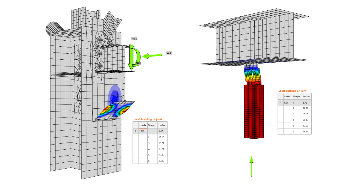
Ejemplo 1
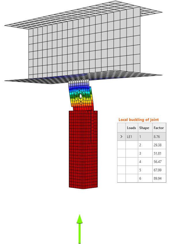
En el primer ejemplo, la fuerza de compresión se aplica a la viga conectada mediante una placa de unión.

Se proporcionan los resultados del cálculo geométricamente lineal y el primer factor es 8,76. Según EN 1993-1-1:2005 Cl. 5.2.1, el valor límite es 15 porque esta junta es crítica para la estabilidad de la propia viga y la conclusión es que la unión no superó el análisis de pandeo. Sin mencionar que esta placa de unión unilateral es peligrosa en este arriostramiento en la configuración de compresión.
Lea más aquí sobre cómo calcular la resistencia al pandeo de una placa de unión.
Ejemplo 2
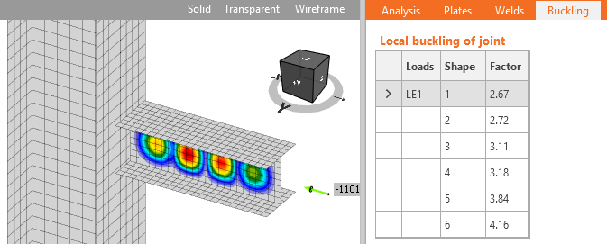
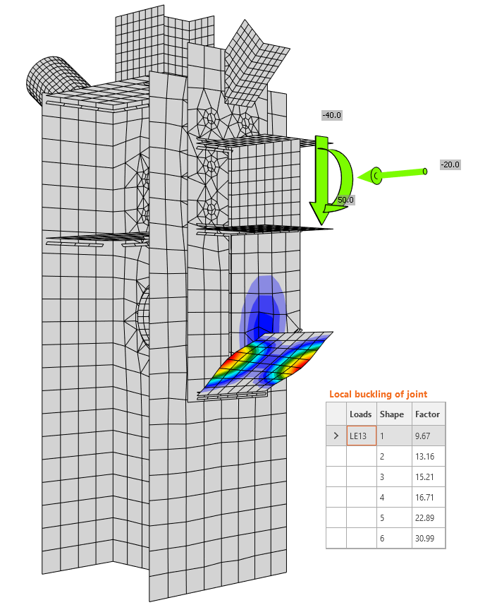
Por otro lado, en el caso de la mayoría de las placas en uniones, puede producirse pandeo local y el valor máximo del factor crítico de pandeo, αcr, que requiere un análisis exhaustivo es generalmente menor. Se ha verificado que para los rigidizadores y el panel de alma del pilar a cortante, no es necesario tener en cuenta el pandeo si el factor crítico de pandeo es superior a 3.
Debemos determinar el valor límite correcto para cada componente y decidir. Este ejemplo muestra que el primer modo de pandeo es el de un rigidizador con factor αcr = 8,76 >> 3. En este ejemplo, este primer modo de pandeo no es peligroso.
Al realizar el análisis de pandeo y tratar los resultados, es necesario aplicar el criterio de ingeniería. La cuestión es cuándo utilizar los límites globales o locales del factor crítico de pandeo y, para la respuesta correcta, el conocimiento de la topología y el sistema estructural de la estructura diseñada es crucial. Si bien IDEA StatiCa tiene la capacidad de proporcionar formas de pandeo y el factor crítico de cualquier parte de la junta, no proporciona la verificación normativa de pandeo según la normativa.
Cuando los resultados de las formas de pandeo nos dan valores negativos, no significa que el cálculo haya fallado o que el resultado sea incorrecto. Lo que ocurre exactamente en estos casos se explica en este artículo de la base de conocimiento.
Un ejemplo práctico de la evaluación del análisis de pandeo de un elemento se presentó en este vídeo del seminario web:
Fundamentos Teóricos
Para una comprensión más profunda del tema del pandeo y la solución de IDEA StatiCa, lea la información esencial sobre el análisis de pandeo en nuestros artículos de Fundamentos Teóricos.
IDEA StatiCa Connection - Diseño estructural de uniones de acero
IDEA StatiCa Member - Estabilidad de elementos
Tutoriales
Hemos creado tutoriales paso a paso para configurar el modelo y ejecutar el análisis. Encuentre los enlaces a continuación:
Diseño estructural de una viga transversal de acero afectada por pandeo lateral torsional (EN)
Diseño estructural y verificación normativa de un pórtico de acero (EN)
Análisis de pandeo de una unión de acero (EN)