
Soldadura en ángulo en unión viga-columna
Descripción
El objeto de este capítulo es la verificación del método de los elementos finitos basado en componentes (CBFEM) para una soldadura en ángulo en una unión viga-columna rigidizada con el método de componentes (CM). Una viga de sección abierta IPE se conecta a una columna de sección abierta HEB400. Los rigidizadores están en el interior de la columna frente a las alas de la viga. La sección de la viga es el parámetro variable. Se consideran tres casos de carga, es decir, la viga está cargada a tracción, cortante y flexión.
Modelo analítico
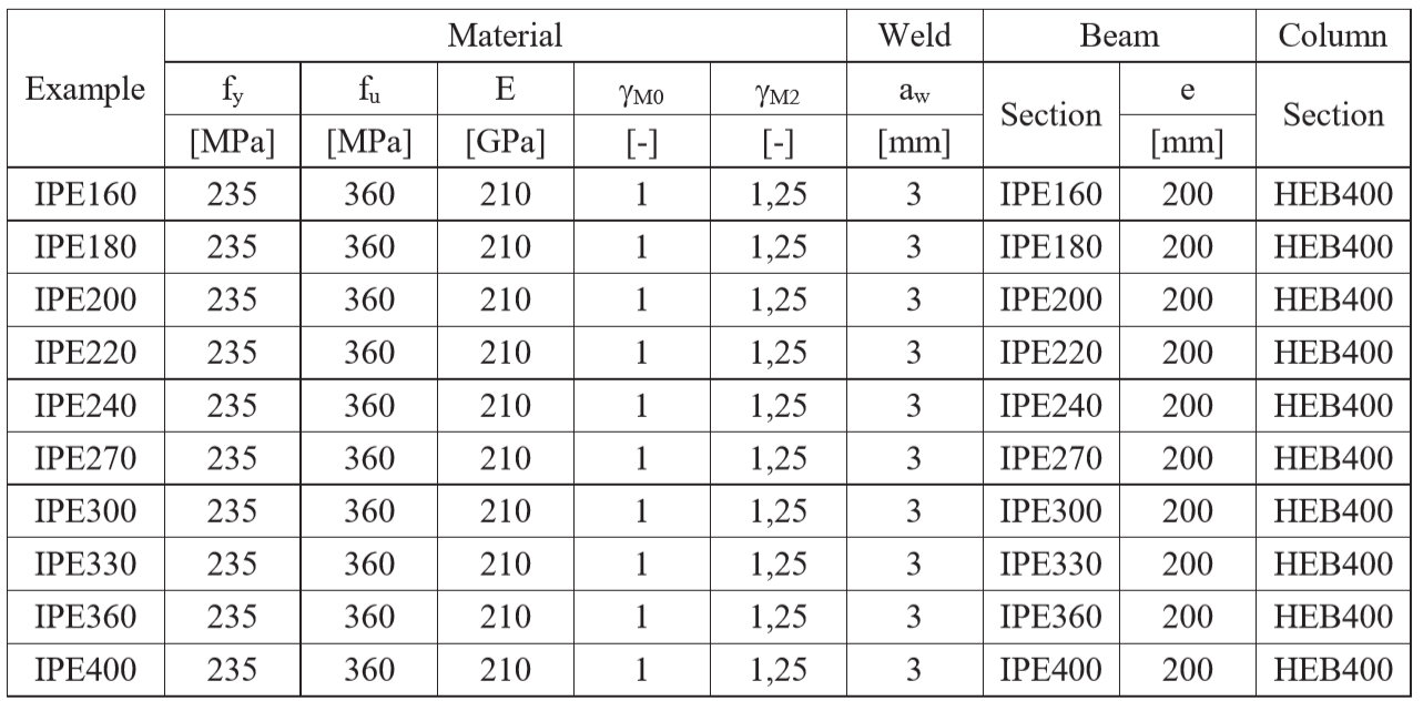
La soldadura en ángulo es el único componente examinado en el estudio. Las soldaduras se diseñan según el Capítulo 4 de EN 1993-1-8:2005 para ser el componente más débil de la unión. La resistencia de cálculo de la soldadura en ángulo se describe en la Sección 4.1. En la Tab. 4.4.1 se ofrece una visión general de los ejemplos considerados y el material. La geometría de la unión con dimensiones se muestra en la Fig. 4.4.1.
Tab. 4.4.1 Resumen de ejemplos
Cálculo manual de la fuerza normal N
\[\sqrt{ \sigma_{\perp}^2 + 3 \cdot \left( \tau_{\perp}^2 + \tau_{\parallel}^2\right)} \leq \frac{f_u}{\beta_{\mathrm{w}} \cdot \gamma_{\mathrm{M2}}}\]
\[\sigma_{\perp} = \tau_{\perp} = \frac{\sigma_{N}}{\sqrt{2}} = \frac{N}{l \cdot a}\cdot \frac{1}{\sqrt{2}} \]
\[ \tau_{\parallel} = 0\]
\[ \sqrt{ \left( \frac{\sigma_{N}}{\sqrt{2}} \right)^2 + 3 \cdot \left( \frac{\sigma_{N}}{\sqrt{2}} \right)^2} \leq \frac{f_u}{\beta_{\mathrm{w}} \cdot \gamma_{\mathrm{M2}}}\]
\[ \sqrt{ \left( \frac{N}{l \cdot a}\cdot \frac{1}{\sqrt{2}} \right)^2 + 3 \cdot \left( \frac{N}{l \cdot a}\cdot \frac{1}{\sqrt{2}} \right)^2} \leq \frac{f_u}{\beta_{\mathrm{w}} \cdot \gamma_{\mathrm{M2}}}\]
\[ N \leq \frac{f_{u} \cdot l \cdot a }{\beta_{\mathrm{w}} \cdot \gamma_{\mathrm{M2}} \cdot \sqrt{2}} \]
Donde:
\(a\) - espesor de garganta de la soldadura
\(N\) - fuerza normal que actúa sobre la viga
\(l\) - longitud total de las soldaduras
\(\beta_{\mathrm{w}}\) - factor de correlación tomado de EN 1993-1-8 Tabla 4.1
\(f_u\) - resistencia última a tracción nominal de la parte más débil unida
\(\gamma_{\mathrm{M2}}\) - factor parcial de seguridad para soldaduras
Cálculo manual de la fuerza cortante V
El cálculo manual presentado en este capítulo se basa en ciertas hipótesis. La fuerza cortante \(V\) es transmitida exclusivamente por la soldadura en el alma. El momento flector resultante de la excentricidad de la fuerza que actúa sobre las soldaduras puede atribuirse a las soldaduras de las alas. El módulo resistente de la sección de soldadura de las soldaduras de las alas \(W\) se determina no por la distancia medida desde el centro de gravedad de las soldaduras, sino desde los bordes del ala hasta el centro de gravedad de la viga, tal como se calcula en la práctica.
Las siguientes ecuaciones demuestran la derivación de la capacidad portante de la soldadura para la fuerza cortante y el momento flector según el CM. La tensión equivalente se especifica en EN 1993-1-8, Ecuación (4.1). Para el cálculo de la resistencia a momento flector, se asumió el módulo resistente plástico de la sección.
\[\sqrt{ \sigma_{\perp} + 3 \cdot \left( \tau_{\perp}^2 + \tau_{\parallel}^2\right)} \leq \frac{f_u}{\beta_{\mathrm{w}} \cdot \gamma_{\mathrm{M2}}}\]
\[V \le \min \left \{ \frac{f_\mathrm{u} \cdot l_V \cdot a}{\sqrt{3} \cdot \beta_{\mathrm{w}} \cdot \gamma_{M2}} , \, \frac{f_\mathrm{u} \cdot W}{\sqrt{2} \cdot \beta_{\mathrm{w}} \cdot \gamma_{\mathrm{M2}} \cdot e} \right \} \]
Donde:
\(e\) - excentricidad de la fuerza respecto a las soldaduras de la viga
\(a\) - espesor de garganta de la soldadura
\(V\) - fuerza cortante que actúa sobre la viga
\(W= W_\mathrm{pl,flange}\) - módulo resistente de la sección de soldaduras
\(A_\mathrm{w,top,f} = B \cdot a\) - área de soldadura en el borde del ala superior
\(A_\mathrm{w,bottom,f} = (B-t_\mathrm{w}) \cdot a\) - área de soldadura en el borde del ala inferior
\(z_\mathrm{w,top,f} = H / 2 \) - brazo de palanca de la soldadura en el borde del ala superior
\(z_\mathrm{w,bottom,f} = (H - t_\mathrm{f}) / 2 \) - brazo de palanca de la soldadura en el borde del ala inferior
\(W_\mathrm{pl,flange} = 2 \cdot \left(A_\mathrm{w,top,f} \cdot z_\mathrm{w,top,f} + A_\mathrm{w,bottom,f} \cdot z_\mathrm{w,bottom,f}\right)\) - módulo resistente plástico del ala
\(l_{\mathrm{V}}\) - longitud total de las soldaduras del alma
\(\beta_{\mathrm{w}}\) - factor de correlación tomado de EN 1993-1-8 Tabla 4.1
\(f_\mathrm{u}\) - resistencia última a tracción nominal de la parte más débil unida
\(\gamma_{\mathrm{M2}}\) - factor parcial de seguridad para soldaduras
\(H\) - altura de la viga IPE
\(B\) - anchura de la viga IPE
\(t_\mathrm{w}\) - espesor del alma de la viga IPE
\(t_\mathrm{f}\) - espesor del ala de la viga IPE
Cálculo manual del momento flector M
En el cálculo del momento flector sin ninguna interacción con la fuerza cortante, se asumió el módulo resistente plástico de toda la sección de soldadura (tanto alrededor de las alas como alrededor del alma).
\[\sqrt{ \sigma_{\perp}^2 + 3 \cdot \left( \tau_{\perp}^2 + \tau_{\parallel}^2\right)} \leq \frac{f_u}{\beta_{\mathrm{w}} \cdot \gamma_{\mathrm{M2}}}\]
\[\sigma_{\perp} = \tau_{\perp} = \frac{\sigma_{N}}{\sqrt{2}} = \frac{M}{W}\cdot \frac{1}{\sqrt{2}} \]
\[ \tau_{\parallel} = 0\]
\[ \sqrt{ \left( \frac{\sigma_{N}}{\sqrt{2}} \right)^2 + 3 \cdot \left( \frac{\sigma_{N}}{\sqrt{2}} \right)^2} \leq \frac{f_u}{\beta_{\mathrm{w}} \cdot \gamma_{\mathrm{M2}}}\]
\[ \sqrt{ \left( \frac{M}{W}\cdot \frac{1}{\sqrt{2}} \right)^2 + 3 \cdot \left( \frac{M}{W}\cdot \frac{1}{\sqrt{2}} \right)^2} \leq \frac{f_u}{\beta_{\mathrm{w}} \cdot \gamma_{\mathrm{M2}}}\]
\[ M \leq \frac{f_{u} \cdot W }{\beta_{\mathrm{w}} \cdot \gamma_{\mathrm{M2}} \cdot \sqrt{2}} \]
\[ \sigma_{\perp} \leq \frac{f_{u} \cdot 0.9}{ \gamma_{\mathrm{M2}}} \]
\[ M \leq \frac{f_{u} \cdot W \cdot 0.9 \cdot \sqrt{2}}{ \gamma_{\mathrm{M2}} } \]
Donde:
\(a\) - espesor de garganta de la soldadura
\(W \) - módulo resistente plástico de la sección de soldadura
\(M\) - el momento flector que actúa sobre la viga
\(\beta_{\mathrm{w}}\) - factor de correlación tomado de EN 1993-1-8 Tabla 4.1
\(f_u\) - resistencia última a tracción nominal de la parte más débil unida
\(\gamma_{\mathrm{M2}}\) - factor parcial de seguridad para soldaduras
Modelo numérico
El componente de soldadura en CBFEM se describe en Antecedentes teóricos generales y Antecedentes teóricos EN.
En este estudio se utiliza un material elastoplástico no lineal para las soldaduras. La deformación plástica límite se alcanza en la parte más larga de la soldadura y los picos de tensión se redistribuyen.
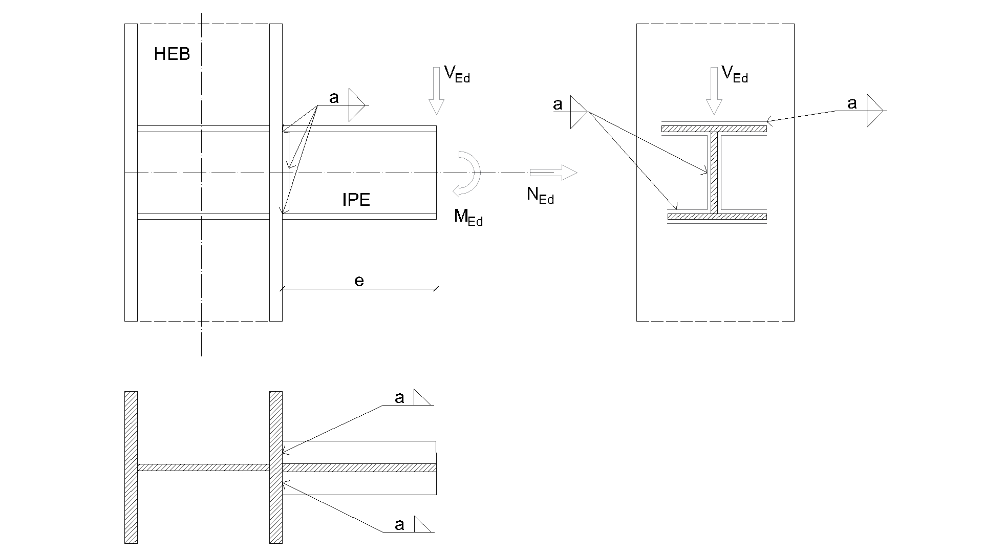
\[ \textsf{\textit{\footnotesize{Fig. 4.4.1 Geometría de la unión con dimensiones}}}\]
Verificación de la resistencia
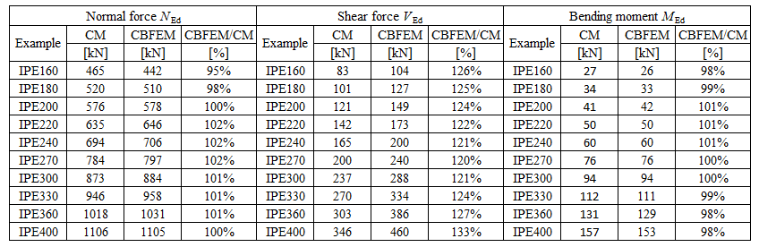
La resistencia de cálculo calculada por el software CBFEM Idea RS se compara con los resultados del CM. Se comparan las resistencias de cálculo de las soldaduras, véase Tab. 4.4.2. El estudio se realiza para una sección de viga con un parámetro y tres casos de carga: fuerza normal NEd, fuerza cortante VEd y momento flector MEd.
Tab. 4.4.2 Comparación de CBFEM y CM
Se comparan los resultados de CBFEM y CM y se presenta un estudio de sensibilidad. La influencia de la sección transversal de la viga en la resistencia de cálculo de una unión viga-columna soldada cargada a tracción se muestra en la Fig. 4.4.2, a cortante en la Fig. 4.4.3 y a flexión en la Fig. 4.4.4. El estudio muestra una buena concordancia para todos los casos de carga aplicados.

\[ \textsf{\textit{\footnotesize{Fig. 4.4.2}}}\]
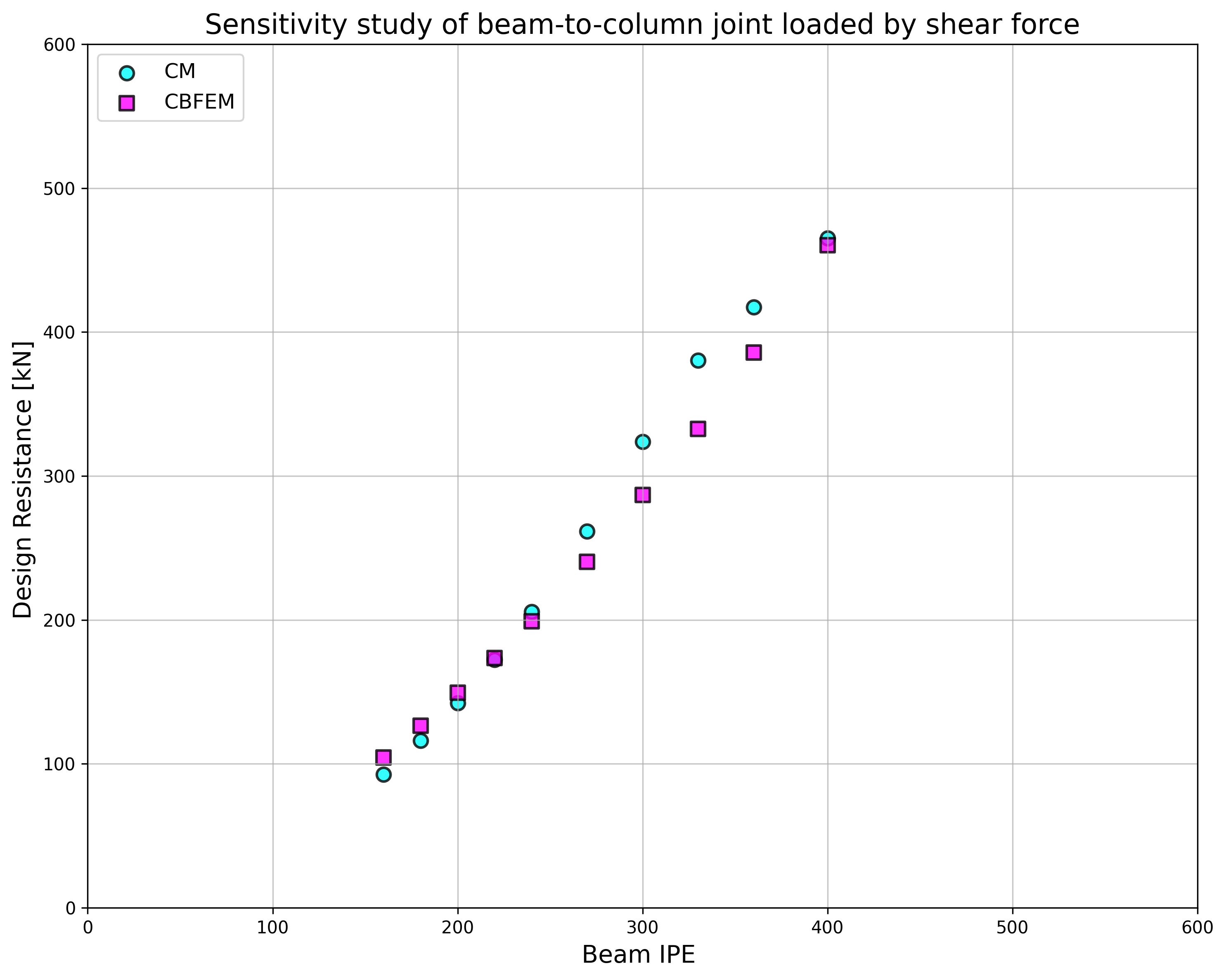
\[ \textsf{\textit{\footnotesize{Fig. 4.4.3}}}\]
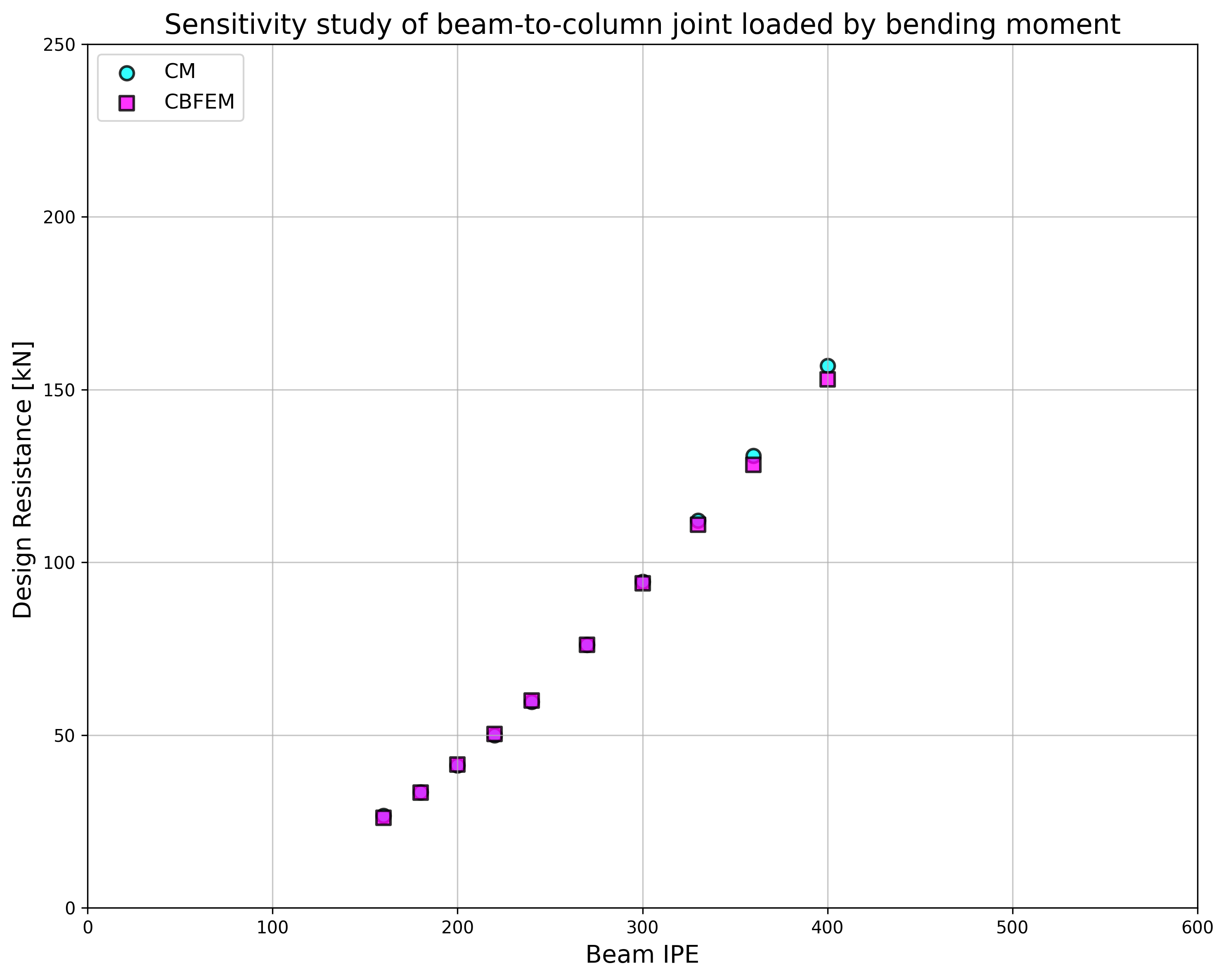
\[ \textsf{\textit{\footnotesize{Fig. 4.4.4}}}\]
Para ilustrar la precisión del modelo CBFEM, los resultados del estudio de sensibilidad se resumen en un diagrama que compara las resistencias de cálculo de CBFEM y CM, véase Fig. 4.4.5. Los resultados muestran que la diferencia entre los dos métodos de cálculo es en todos los casos inferior al 10%.
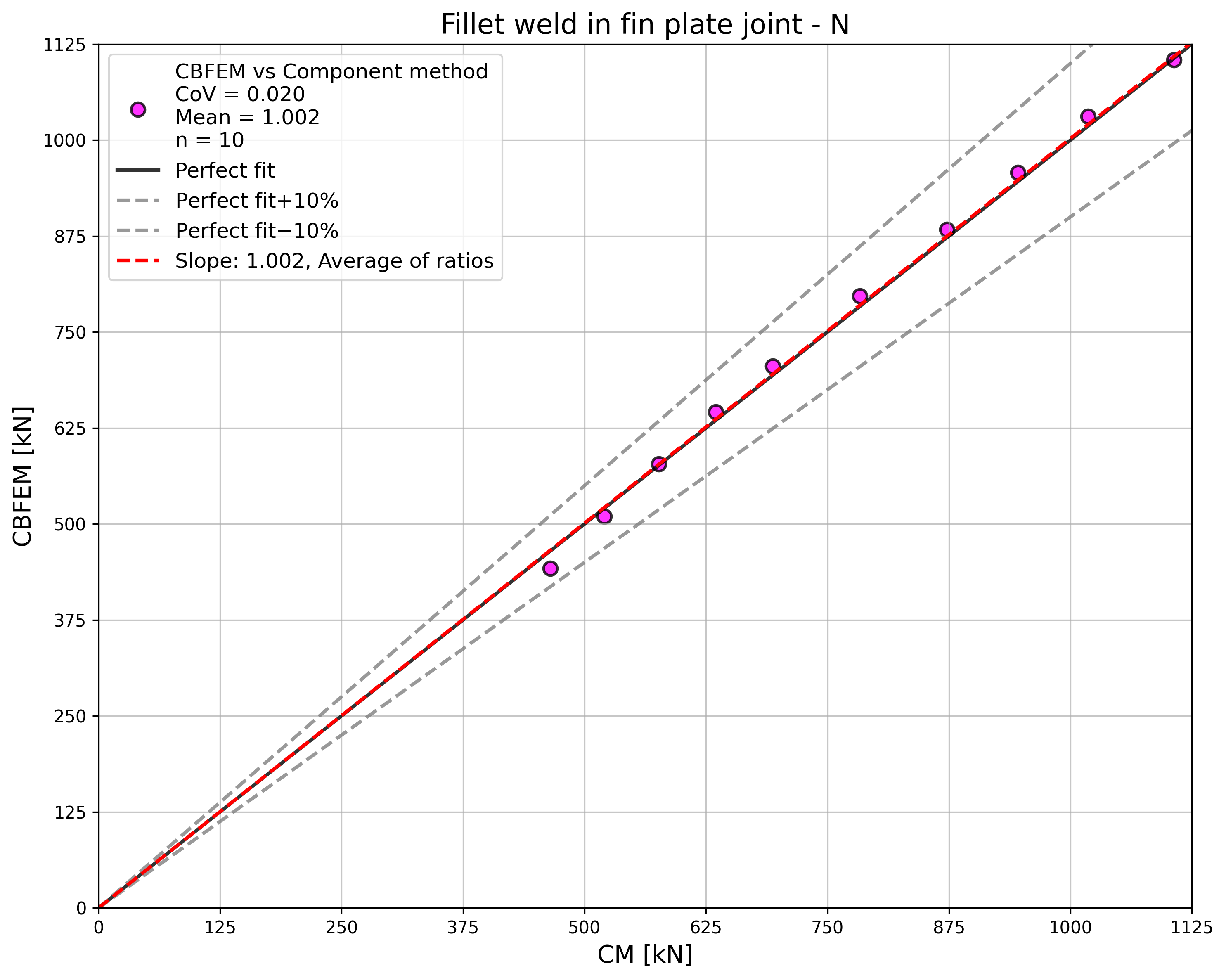
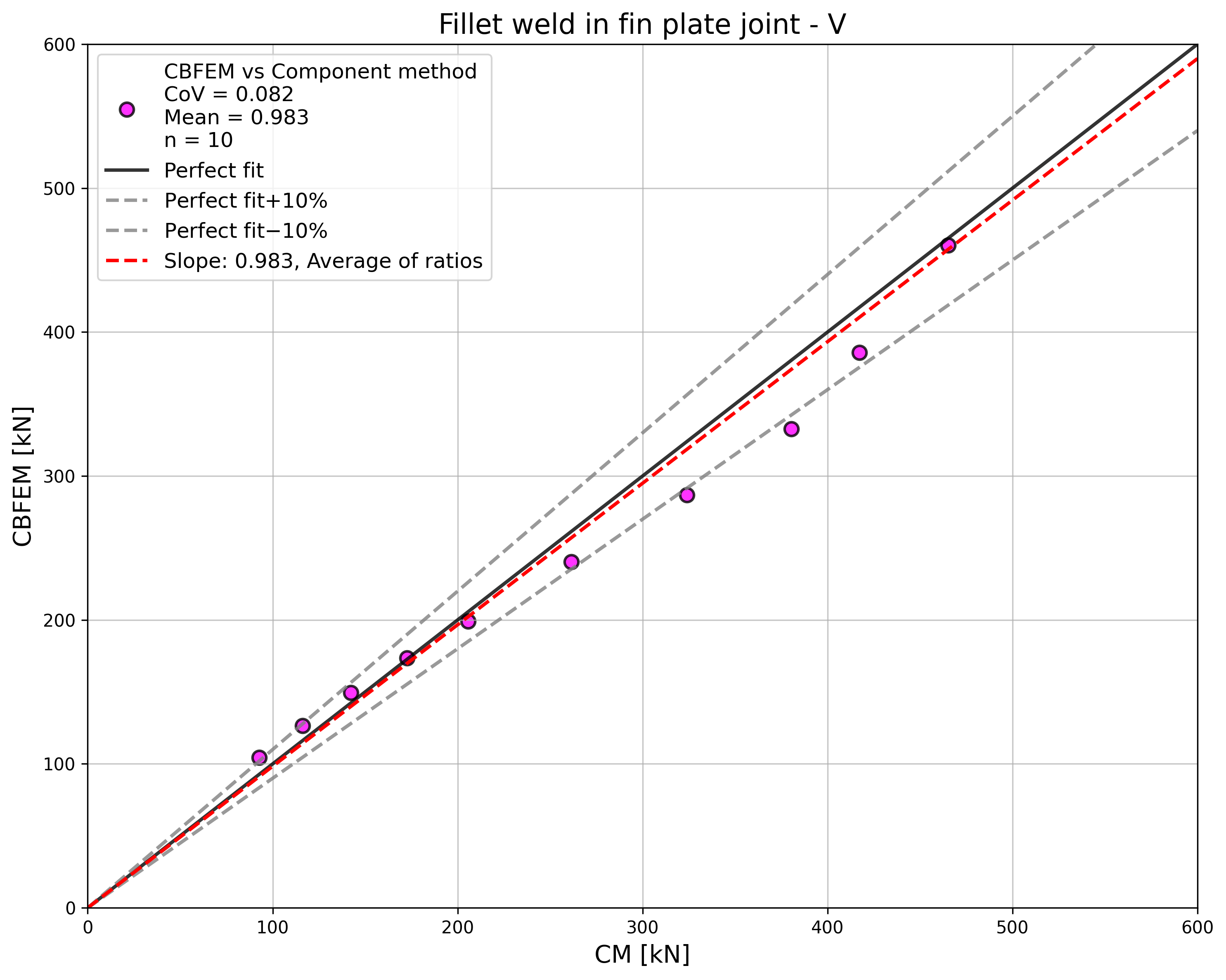
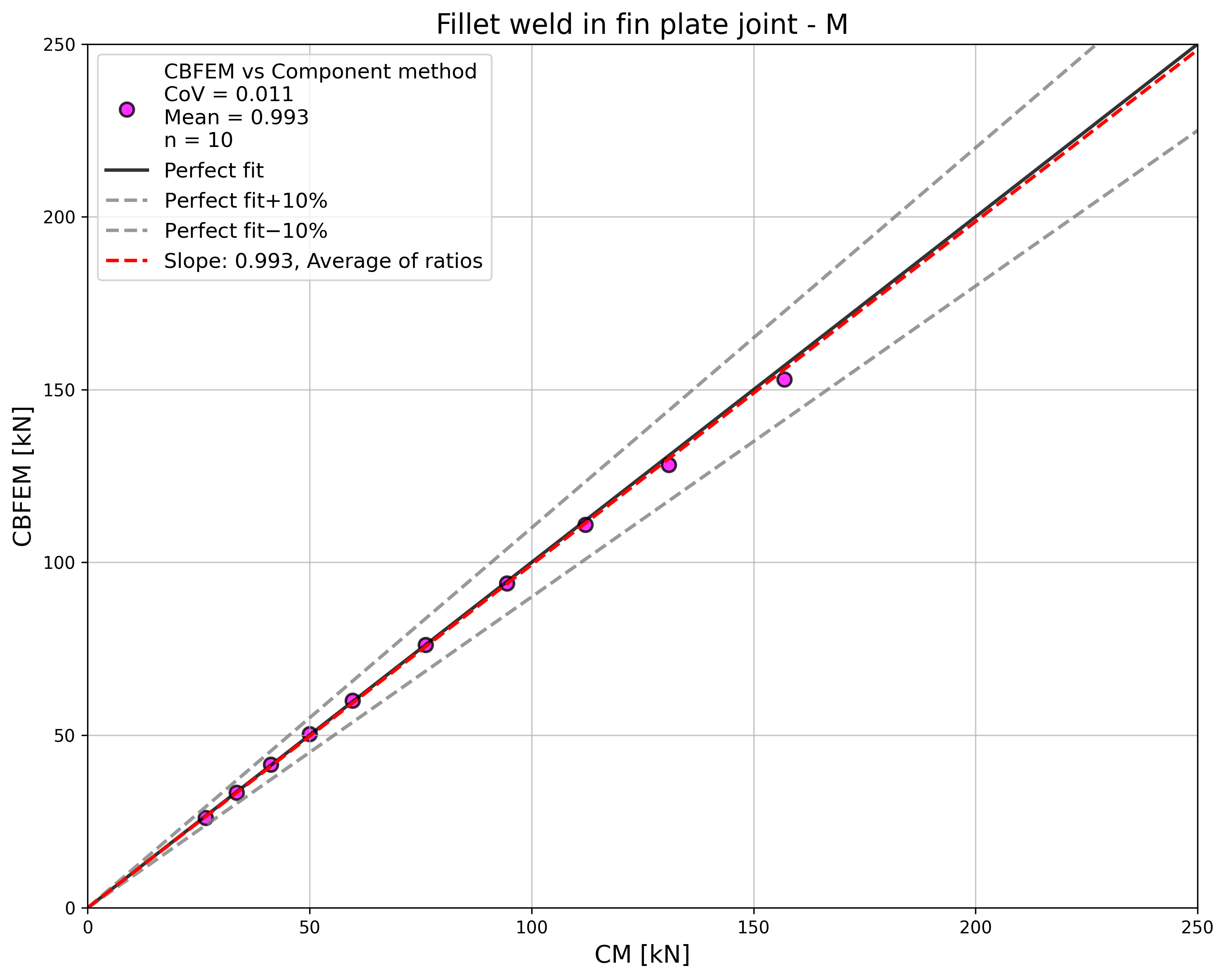
\[ \textsf{\textit{\footnotesize{Fig. 4.4.5 Verificación de CBFEM respecto a CM}}}\]
Ejemplo de referencia
Datos de entrada
Columna
- Acero S235
- HEB 400
Viga
- Acero S235
- IPE 160
- Excentricidad de la fuerza respecto a la soldadura x = 400 mm, véase Fig. 4.4.6
Soldadura
- Espesor de garganta aw = 3 mm
Resultados:
- Resistencia de cálculo a cortante VRd = 105 kN
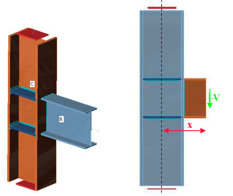
\[ \textsf{\textit{\footnotesize{Fig. 4.4.6 Ejemplo de referencia de la unión viga-columna soldada con excentricidad de la fuerza}}}\]