¿Es suficiente el enfoque analítico para verificar el pandeo de elementos?
En este blog, revisaremos el enfoque analítico, con su determinación de la longitud de pandeo, que se adoptó para calcular y realizar la verificación normativa de los problemas de estabilidad de elementos de acero, como el pandeo de columnas y el pandeo lateral por torsión de vigas. Este procedimiento, que trata la posible pérdida de estabilidad, está bien establecido en normas de diseño como EN 1993-1-1 o AISC 360-22.
¿Pero pueden los cálculos manuales sobrevivir al auge de las tecnologías basadas en el Método de los Elementos Finitos y las soluciones numéricas? ¿Siguen demostrando ser fiables y seguros?
Exploremos el tema del pandeo de elementos de acero con un ejemplo sencillo. No hay mejor fuente de aprendizaje que una obra de diseño real o, en efecto, un error.
El método estándar de análisis estructural
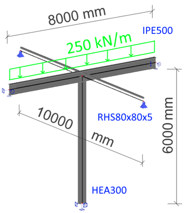
En primer lugar, mantendremos los datos del proyecto en el anonimato. Nos centraremos en un segmento simple de viga-columna ubicado en el interior de un edificio para proporcionar un espacio de gran luz. En ambos lados, está conectado al cuerpo rigidizado del edificio (véase la imagen a continuación del detalle de la unión con vistas de sección en azul y verde).
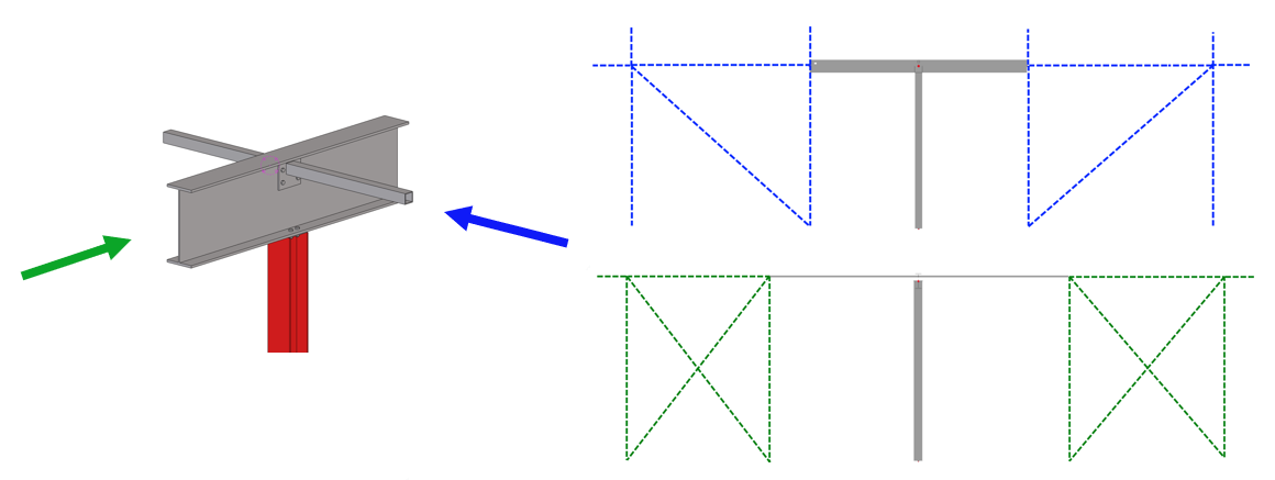
La columna HEA 300 tiene 6 m de longitud y está empotrada en la base mediante una gruesa placa base y cuatro pernos de anclaje M30. La viga IPE 500 tiene 8 m de longitud, está apoyada en la parte superior de la columna y cargada en el eje del elemento por una carga uniformemente distribuida de 250 kN/m. La viga está apoyada en ambos lados por arriostramientos RHS 80x80x5 de 5 m de longitud. Todo el acero es de grado S355.
Paso 1: El modelo estructural global
El primer paso es crear y analizar el modelo global. Para este estudio, se empleó SCIA Engineer, aunque cualquier otra solución de análisis por elementos finitos puede sustituirlo (SAP2000, ETABS, Robot, STAAD.Pro, etc.). El modelo es sencillo y se construye de forma directa; la única cuestión son los apoyos en los extremos.
Según la descripción del proyecto, podemos decir que la base de la columna, con su sólido anclaje y su gruesa placa base, tiene un apoyo empotrado, la viga principal tiene un apoyo articulado con torsión fija, y los elementos de arriostramiento, que proporcionan estabilidad frente al pandeo lateral por torsión, tienen apoyos puramente articulados.
SCIA Engineer proporciona una verificación completa en ELU, así como la verificación de estabilidad mediante el enfoque analítico integrado con las longitudes de pandeo, la fuerza crítica, el momento crítico y la resistencia global al pandeo de los elementos basada en la carga crítica de Euler.
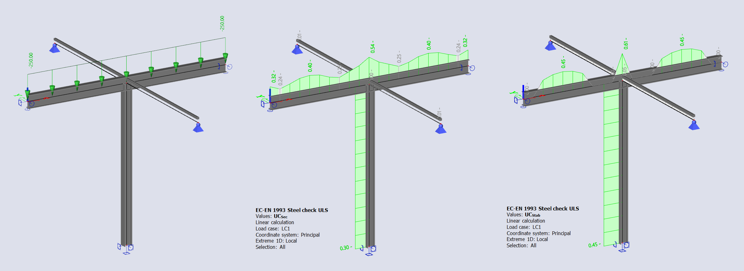
En los resultados del cálculo, podemos leer que la utilización de la sección alcanza un máximo del 54% para la viga y del 30% para la columna. La verificación de estabilidad proporciona una utilización del pandeo del elemento del 45% en el vano central de la viga (pandeo lateral por torsión bajo el momento flector My) y del 45% en la columna (arqueamiento bajo compresión N). El modelo global ha superado las verificaciones normativas.
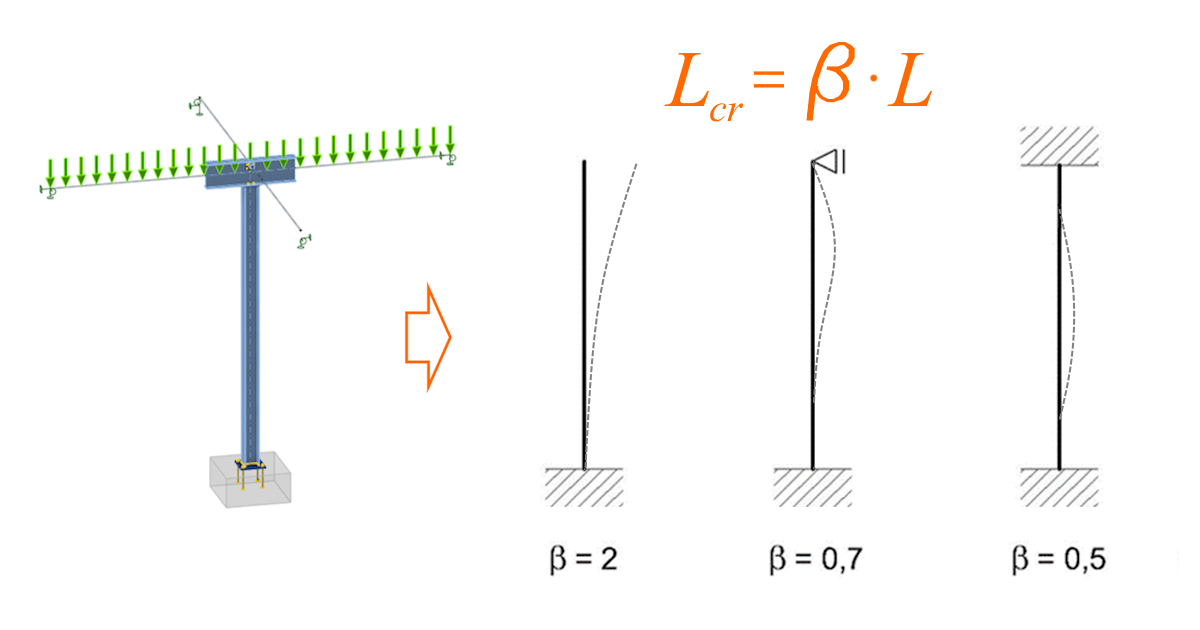
Paso 2: Curva de pandeo y longitud de pandeo
Verifiquemos los resultados del software con un cálculo manual. Nos centraremos aquí en la verificación de estabilidad y seguiremos el enfoque analítico descrito en el capítulo 6.3 de EN 1993-1-1, Resistencia al pandeo de elementos. Dado que el modelo global es simétrico en ambas direcciones, el enfoque analítico es sencillo. Pero primero, necesitamos elegir la forma de pandeo para calcular la longitud de pandeo como Lcr=beta*L.
Para el problema de pandeo de la columna bajo compresión, elegimos la base empotrada y la parte superior articulada, ya que el anclaje está diseñado como rígido, la parte superior de la columna está retenida por la viga en una dirección y por los elementos de arriostramiento en la otra dirección. Esto resulta en un factor beta de 0,7 para calcular la longitud de pandeo.
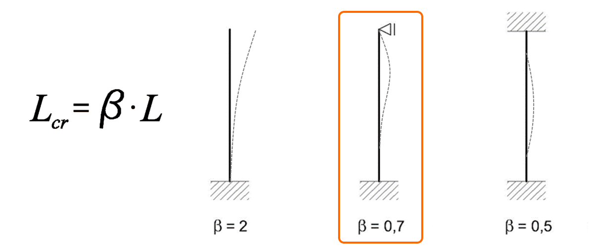
Para la viga, inspeccionaremos el pandeo lateral por torsión del vano central entre el apoyo en el extremo y la unión con la columna. Gracias a los apoyos en ambos lados del vano central, determinamos el factor beta como 0,5.

Ahora seguimos las ecuaciones según la norma: sumamos las propiedades de la sección y del acero y determinamos los factores y parámetros apropiados, como la esbeltez y los factores de imperfección para las curvas de pandeo, la fuerza crítica y el momento crítico, para finalmente calcular la resistencia de cálculo al pandeo de un elemento comprimido Nb,Rd y el momento resistente de cálculo al pandeo Mb,Rd.
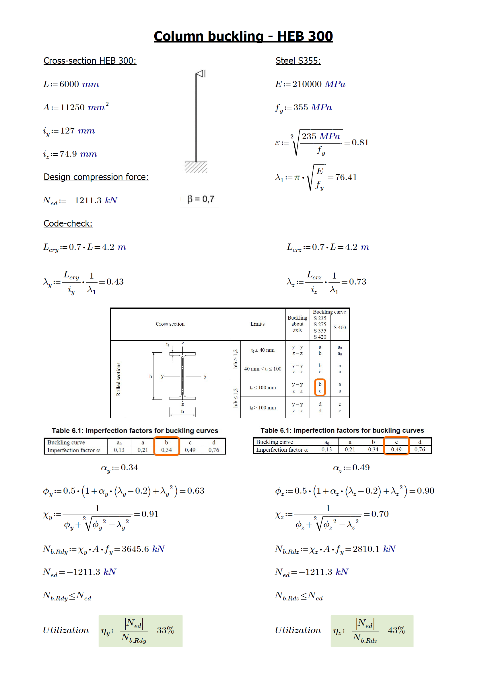
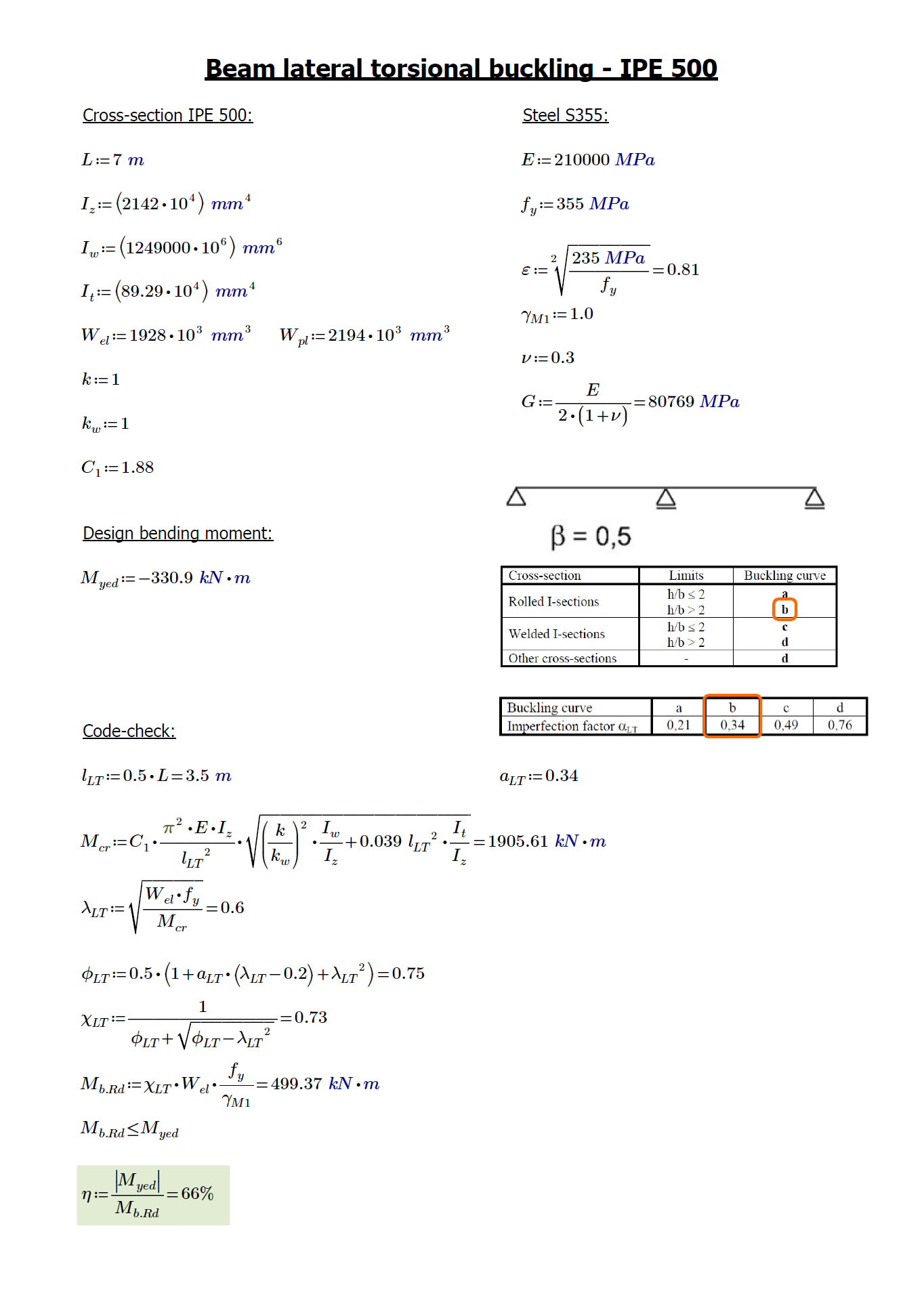
Los resultados de nuestro cálculo manual muestran una buena concordancia con los obtenidos del análisis de SCIA Engineer. La utilización máxima de la columna en estabilidad es del 43% y la utilización de la viga en estabilidad lateral es del 66%. Ambos elementos estructurales han superado las verificaciones normativas.
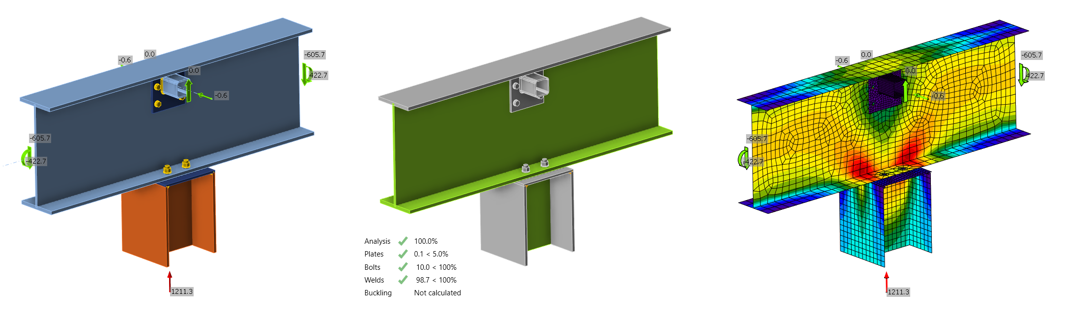
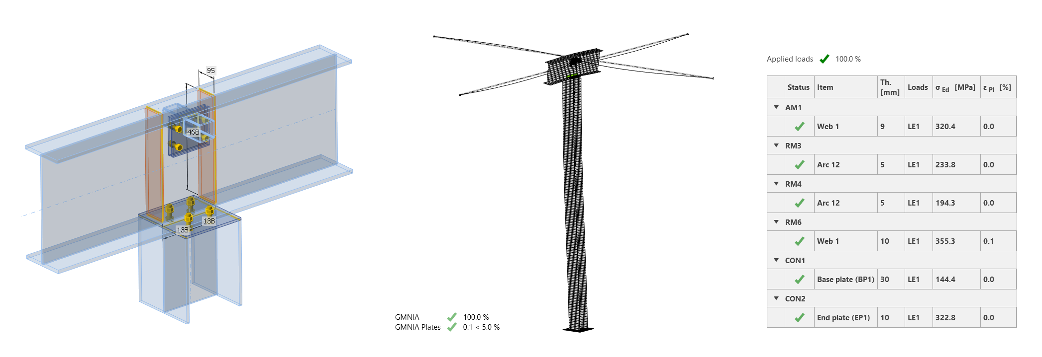
Paso 3: Verificación normativa de la unión
Para la verificación de las uniones, se utilizó IDEA StatiCa. Esto implicó importar la geometría y los efectos de carga a través del enlace BIM a Checkbot, abrir el nodo en la aplicación Connection, diseñarlo y calcularlo, y entregar el informe. Tan sencillo como escribir estas tres líneas de texto, el trabajo llevó un minuto y todas las partes de la unión superaron las verificaciones normativas.
Entonces, ¿qué está mal? Oh... es el pandeo
En las líneas anteriores, básicamente repetimos el proceso de diseño real. ¿Todo bien hasta ahora? ¡Sorpresaaa, el segmento colapsó!!! Sí, poco después de que el proyecto finalizara, el sistema viga-columna perdió su estabilidad.
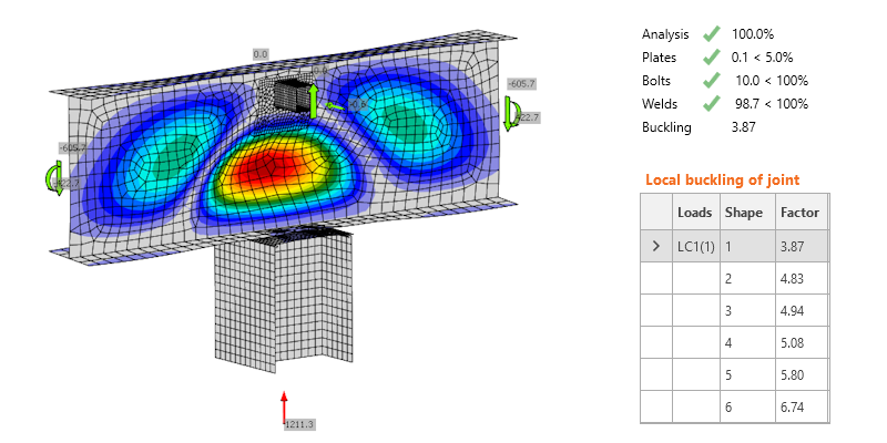
Para la investigación teórica de la causa del fallo, podemos utilizar el juicio de ingeniería experimentado o IDEA StatiCa Member, la herramienta de análisis más avanzada actualmente para elementos sometidos a pandeo.
IDEA StatiCa Member muestra la verdad
Usando los enlaces BIM, podemos importar nuevamente la columna y la viga investigadas con la carga distribuida y los elementos de arriostramiento desde SCIA Engineer a Checkbot y abrirlo en la aplicación Member. O bien, podemos modelar fácilmente la parte estructural desde cero. En cualquier caso, tras un rápido ensamblaje del modelo, podemos ejecutar el análisis en tres pasos.
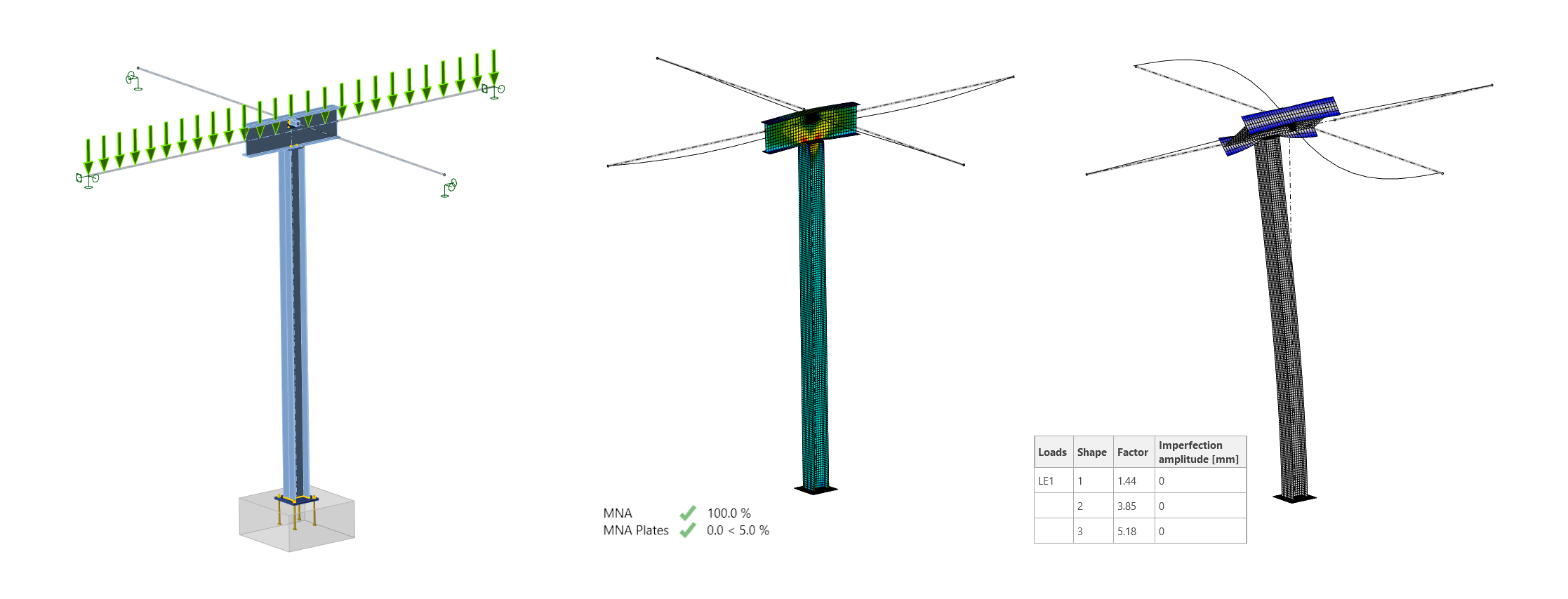
Para el análisis GMNIA (análisis no lineal geométrica y materialmente con imperfecciones), necesitamos introducir la amplitud de imperfección. A partir de una única ecuación, obtenemos 24 mm para la primera forma de pandeo y 2 mm para la segunda forma de pandeo. Ambas imperfecciones de pandeo y formas de pandeo se considerarán conjuntamente.
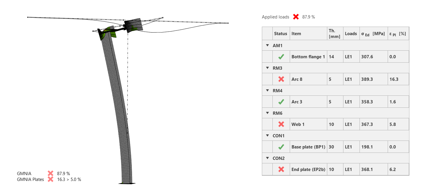
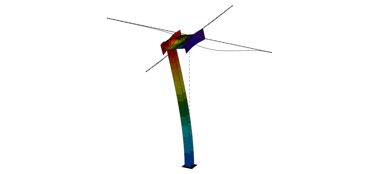
Los resultados del GMNIA muestran un fallo claro del modelo. La columna pandea hacia su parte superior, provocando el vuelco de la viga. Este fue exactamente el modo de fallo de la estructura real.
¿Pero cuál es la diferencia respecto al enfoque analítico? Allí, hicimos una suposición del sistema simplificado (columna empotrada-articulada). Pero, dado que el alma de la viga no es suficientemente rígida, la columna es propensa al pandeo, casi como si estuviera sin apoyo, ¡en el extremo superior!
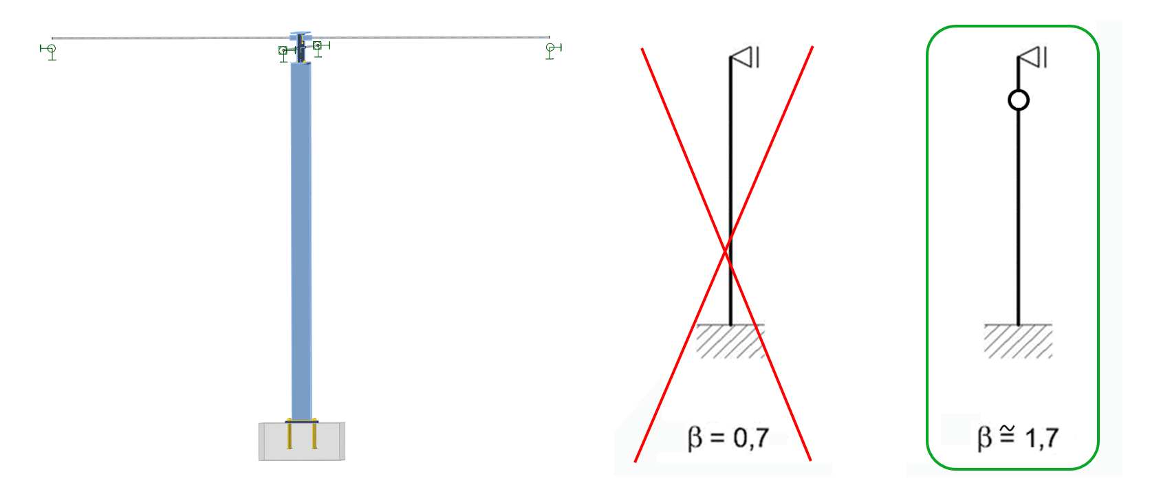
Por tanto, este es el gran error que cometimos durante el proceso analítico: el sistema de columna funciona en realidad de manera diferente a "empotrado-articulado" con un beta de 0,7, y deberíamos definirlo más bien como empotrado-rótula-articulado con un factor beta de aproximadamente 1,7. Esto, por supuesto, llevaría a que las verificaciones normativas del cálculo manual no se superaran.
¿Cómo prevenir el pandeo? ¡Hay que rigidizarlo!
Ahora que hemos revelado y descrito el error, pensemos en cómo podría haberse evitado. Como se mencionó, contar con una buena experiencia y detectar el problema o utilizar la aplicación Member habría prevenido el desastre.
Pero dado que en el trabajo original se utilizó la aplicación Connection, realizar el análisis de pandeo también habría dado una señal de alarma. Aunque los elementos de arriostramiento estabilizan la viga en sus lados, su posición superior y la rigidez general son demasiado bajas, y el alma de la viga es simplemente demasiado alta y flexible.
La reacción inmediata (o requisito previo) es, en efecto, añadir rigidizadores. Estos probablemente no eran deseados debido a los requisitos arquitectónicos o del proyecto y fueron ignorados por un ingeniero sin experiencia, pero quizás añadirlos solo en la parte posterior de la viga habría sido aceptable. Podemos hacerlo en la aplicación Member en segundos, recalcular el proyecto y observar la desaparición de la rótula plástica. El sistema ahora funciona tal como se asumió al principio de la historia (beta de 0,7), y la parte estructural supera todas las verificaciones normativas.
Nota: El papel de los rigidizadores locales en las estructuras de acero es un tema bastante importante, y podemos aprender sobre su impacto a partir de diversas fuentes (incluso publicaciones en redes sociales como el colapso del puente de acero en Albany).
Conclusión
La respuesta a la pregunta del título no es un SÍ o un NO claro. Pero como hemos sido testigos, existen situaciones y proyectos en los que puede cometerse un error crítico dentro del enfoque analítico. Afortunadamente, existe una forma mucho más fiable, rápida, visual y cómoda de hacerlo con IDEA StatiCa Member. ¡Es hora de decir adiós a las estimaciones de longitud de pandeo!
Y para resumir la lección de hoy:
- El enfoque analítico es una simplificación y puede conducir a un error peligroso.
- Los pequeños detalles pueden ser críticos para la estabilidad de toda la estructura.
- Nunca diseñe un detalle de este tipo sin un rigidizador (o IDEA StatiCa Member).
- Para un análisis de 1er orden, en SCIA Engineer (u otra aplicación de análisis por elementos finitos), debe prestar atención a las condiciones de contorno del modelo; con la definición correcta, la longitud de pandeo estaría cerca de 1,7.
- Para un análisis de pandeo más detallado en SCIA Engineer (u otra aplicación de análisis por elementos finitos), puede utilizar módulos y funciones avanzadas para evaluar el pandeo de forma más precisa y segura.
Puede descargar el paquete, que incluye el proyecto de SCIA Engineer, los proyectos de IDEA StatiCa Connection e IDEA StatiCa Member, y el script de MathCad.
Si lo desea, también puede ver la grabación del webinar sobre el mismo tema: ¿Puede el cálculo manual verificar el pandeo de elementos de forma segura?
Prueba IDEA StatiCa gratis
