Nachweis der Längsaussteifung
Motivation
Wie bereits erwähnt, spielt die Längsaussteifung in Stahlhallenkonstruktionen eine entscheidende Rolle. Dieses zuverlässige Element wird aufgrund seiner Wirksamkeit bei der Verbesserung des gesamten Aussteifungsverhaltens im Bauwesen weit verbreitet eingesetzt. Fortschrittliche Simulationswerkzeuge wie IDEA StatiCa Member ermöglichen es Ingenieuren, die Knicklänge präzise zu berechnen und den Einfluss exzentrischer Verbindungen zu berücksichtigen, wodurch die Bemessung und Leistungsfähigkeit von Längsaussteifungssystemen weiter optimiert werden.
Projekt
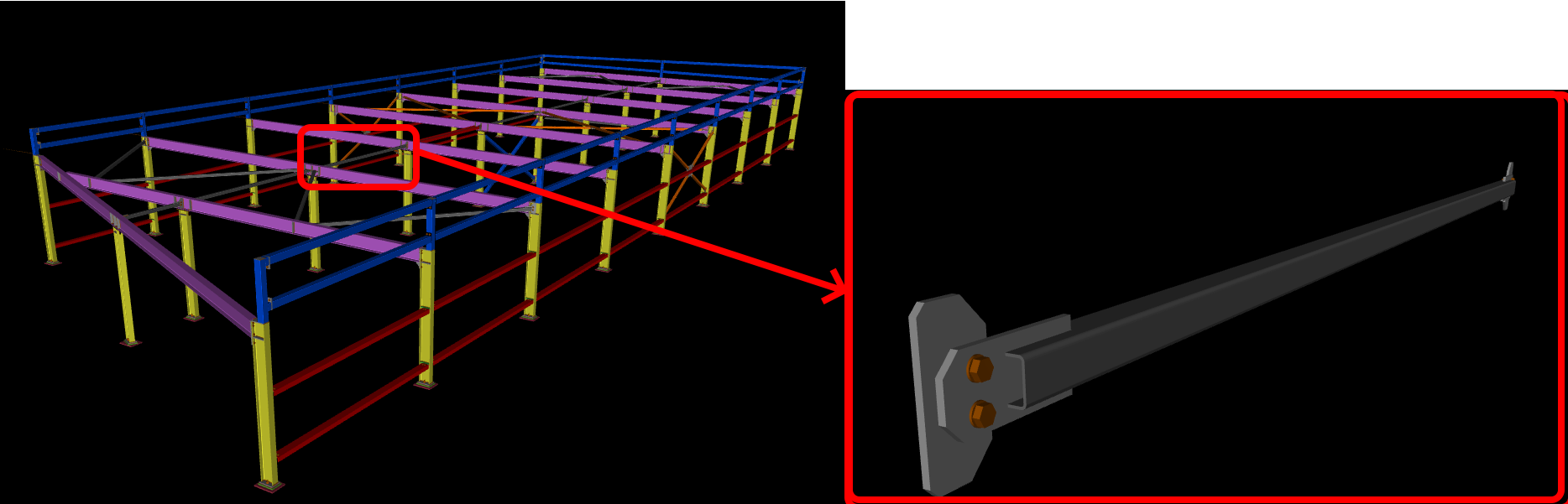
Das Projekt wurde von HESCON s.r.o. durchgeführt, wobei Ingenieur Lucián Lesňák für die Bemessung und den Normnachweis der Halle verantwortlich war. Die Halle hat eine Breite von 8,3 Metern, eine Länge von 22,6 Metern und eine Höhe von 2,3 Metern. Das zu analysierende Schlüsselelement ist ein SHS-Profil 50x50x3 mm, das exzentrisch über ein Knotenblech an ein IPE 180 angeschweißt ist.
Analytische Lösung
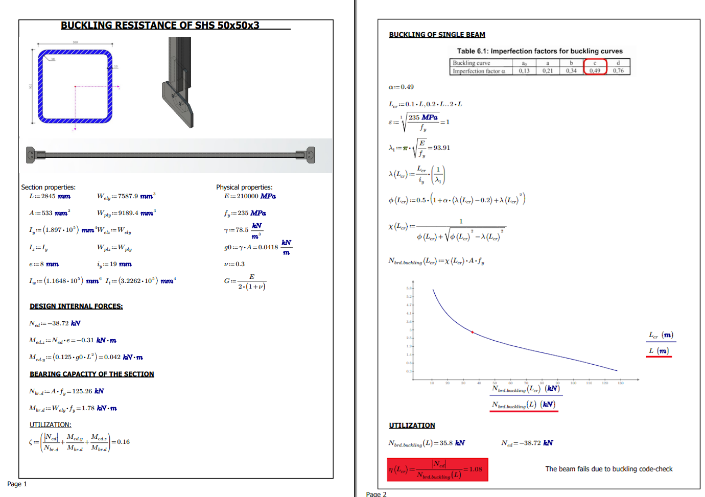
Für eine weiterführende Analyse ist es unerlässlich, das Verhalten des maßgebenden Bauteils per Handrechnung zu ermitteln und zu verstehen. Die Handrechnung erfolgt nach EN 1993-1-1. Die Berechnung berücksichtigt die Bemessungsdruckkraft und führt den Normnachweis für den maßgebenden Knicknachweises durch.
Die Vorteile der Handrechnung:
Verständnis der Grundlagen: Die Durchführung von Handrechnungen ermöglicht es Ingenieuren, ein tiefes Verständnis der grundlegenden Prinzipien und Theorien der Tragwerksanalyse und -bemessung zu erlangen. Sie hilft dabei, eine solide Wissensbasis und Problemlösungskompetenz aufzubauen.
Überprüfung und Validierung: Handrechnungen dienen als wertvolles Werkzeug zur Überprüfung und Validierung der Ergebnisse aus computergestützten Analyse- und Bemessungsprogrammen. Durch unabhängige Berechnungen können Ingenieure die Genauigkeit und Zuverlässigkeit ihrer Bemessungen sicherstellen.
Sensitivitätsanalyse: Handrechnungen ermöglichen es Ingenieuren, Sensitivitätsanalysen durchzuführen, indem sie verschiedene Bemessungsparameter manuell anpassen und deren Auswirkungen auf das gesamte Tragwerksverhalten beobachten. Dies hilft bei der Optimierung der Bemessung und der Identifizierung kritischer Einflussfaktoren auf die Tragwerksleistung.
Schnelle Abschätzungen: Handrechnungen bieten eine schnelle und effiziente Möglichkeit, Tragwerksreaktionen abzuschätzen und die Machbarkeit von Vorentwurfskonzepten zu prüfen. Sie können in frühen Projektphasen eingesetzt werden, wenn eine detaillierte computergestützte Analyse noch nicht erforderlich ist.
Verbesserte Problemlösungskompetenz: Durch den Einsatz von Handrechnungen entwickeln Ingenieure ausgeprägte Problemlösungsfähigkeiten und kritisches Denkvermögen. Sie lernen, komplexe Tragwerksprobleme in einfachere Teilprobleme zu zerlegen, diese systematisch zu analysieren und zu genauen Lösungen zu gelangen.
Bildungszwecke: Handrechnungen werden häufig als Lehrmittel in der Tragwerksplanerausbildung eingesetzt. Sie helfen Studierenden, die zugrunde liegenden Konzepte, Theorien und Gleichungen der Tragwerksanalyse und -bemessung zu verstehen und fördern ein tieferes Verständnis des Fachgebiets.
Insgesamt spielen Handrechnungen im Bereich der Tragwerksplanung eine entscheidende Rolle, indem sie ein gründliches Verständnis der Grundlagen fördern, Genauigkeit sicherstellen, Optimierung erleichtern, schnelle Abschätzungen ermöglichen, Problemlösungskompetenz stärken und Bildungszwecken dienen.
Die Unzulänglichkeiten der Handrechnung:
Menschliche Fehler: Die Genauigkeit von Handrechnungen hängt stark von den Fähigkeiten, der Erfahrung und der Sorgfalt der Ingenieure ab. Fehler bei der Dateneingabe, Einheitenumrechnung oder mathematischen Berechnungen können zu falschen Ergebnissen führen und die Sicherheit und Zuverlässigkeit der Struktur gefährden.
Begrenzte Komplexität: Handrechnungen sind in der Regel auf einfache und überschaubare Tragsysteme beschränkt. Mit zunehmender Komplexität der Struktur steigt auch die Komplexität der Berechnungen, was eine genaue und zuverlässige Durchführung erschwert.
Zeitaufwand: Handrechnungen können zeitaufwändig und arbeitsintensiv sein, insbesondere bei großen und komplexen Strukturen. Dies kann zu Verzögerungen im Projektzeitplan und erhöhten Projektkosten führen.
Begrenzte Optimierung: Handrechnungen sind für Optimierungs- und iterative Bemessungsprozesse wenig geeignet. Sie werden in der Regel erst nach Festlegung des Vorentwurfs durchgeführt, was die Möglichkeit einschränkt, verschiedene Bemessungsvarianten zu erkunden und zu optimieren.
Begrenzte Visualisierung: Handrechnungen bieten eine eingeschränkte Visualisierung des Tragwerksverhaltens, was es erschwert, potenzielle Versagensmodi zu identifizieren oder die gesamte Tragwerksreaktion darzustellen.
Obwohl Handrechnungen mehrere Vorteile bieten, sind sie nicht ohne Einschränkungen und Unzulänglichkeiten. Es ist wichtig, die Vor- und Nachteile von Handrechnungen mit anderen Analysewerkzeugen und -methoden abzuwägen, um genaue und zuverlässige Tragwerksbemessungen sicherzustellen.
Numerische Simulation
Die Tragwerksplaner haben das IDEA StatiCa-Modell eingehend verifiziert, indem sie es mit einer ABAQUS-Lösung verglichen haben. Dieser Prozess zielte darauf ab, sicherzustellen, dass das Modell robust und verlässlich ist und eine zuverlässige Grundlage für die Tragwerksbemessung bietet. Durch diese detaillierte Analyse konnten die Ingenieure potenzielle Verbesserungsbereiche identifizieren, das Modell feinjustieren und noch genauer gestalten. Letztendlich trug dieser Verifizierungsprozess dazu bei, die Gesamtqualität und Sicherheit der Tragwerksbemessung zu erhöhen.
Annahmen von IDEA StatiCa und ABAQUS
Die zur Simulation des numerischen Zwillings verwendeten Annahmen wurden in ABAQUS implementiert. Für die Modellierung wurde das S4R-Element gewählt. Dieses Element ist ein standardmäßiges lineares Viereckselement mit reduzierter Integration, Hourglass-Kontrolle und finiten Membrandehnungen. Zur Modellierung der Schrauben wurde eine Join + Revolute MPC verwendet, zusammen mit kinematischer Kopplung zur Verteilung der Spannungen im Bereich von Mutter und Schraubenkopf. Da im gesamten Modell Stumpfnähte vorhanden sind, wurden lineare Constraint-Ties verwendet, um die Platten miteinander zu verbinden. Das in der Simulation verwendete Werkstoffdiagramm ist identisch mit dem im IDEA StatiCa-Modell verwendeten. Die Kontakte wurden als reibungsfrei definiert. Die Simulation wurde als allgemeine statische Analyse mit geometrisch nichtlinearer Berechnung (große Verschiebungen) durchgeführt. Das Netz im Bereich der Verbindung hat eine maximale Elementgröße von 2 mm, und das SHS 50/50/3 ist in 5 mm große Netzelemente unterteilt.
- Schalenfinite Elemente
- Schrauben – nichtlineare Federn (Interaktion Zug und Querkraft)
- Schweißnähte – Sonderelemente, die die Platten über MPC verbinden
- Reibungsfreie Kontakte – Penalty-Methode
- Werkstoff – bilineares Diagramm mit Verfestigung (isotrope Verfestigungsregel)
- Lineare Beulanalyse – materiell nichtlineare Analyse als Vorlast verwendet; Kontakte sind während der Analyse frei
Den theoretischen Hintergrund können Sie hier nachlesen.
Analytisches Modell
Das analytische Modell wurde über eine Verbindung in allen sechs Freiheitsgraden eingespannt. Die zweite Verbindung schränkt alle Rotationen und Verschiebungen ein, mit Ausnahme der Verschiebungen entlang der Achse des SHS-Bauteils. Dies ist auf die konzentrierten Axialkräfte zurückzuführen, die in das Modell selbst eingeleitet werden.
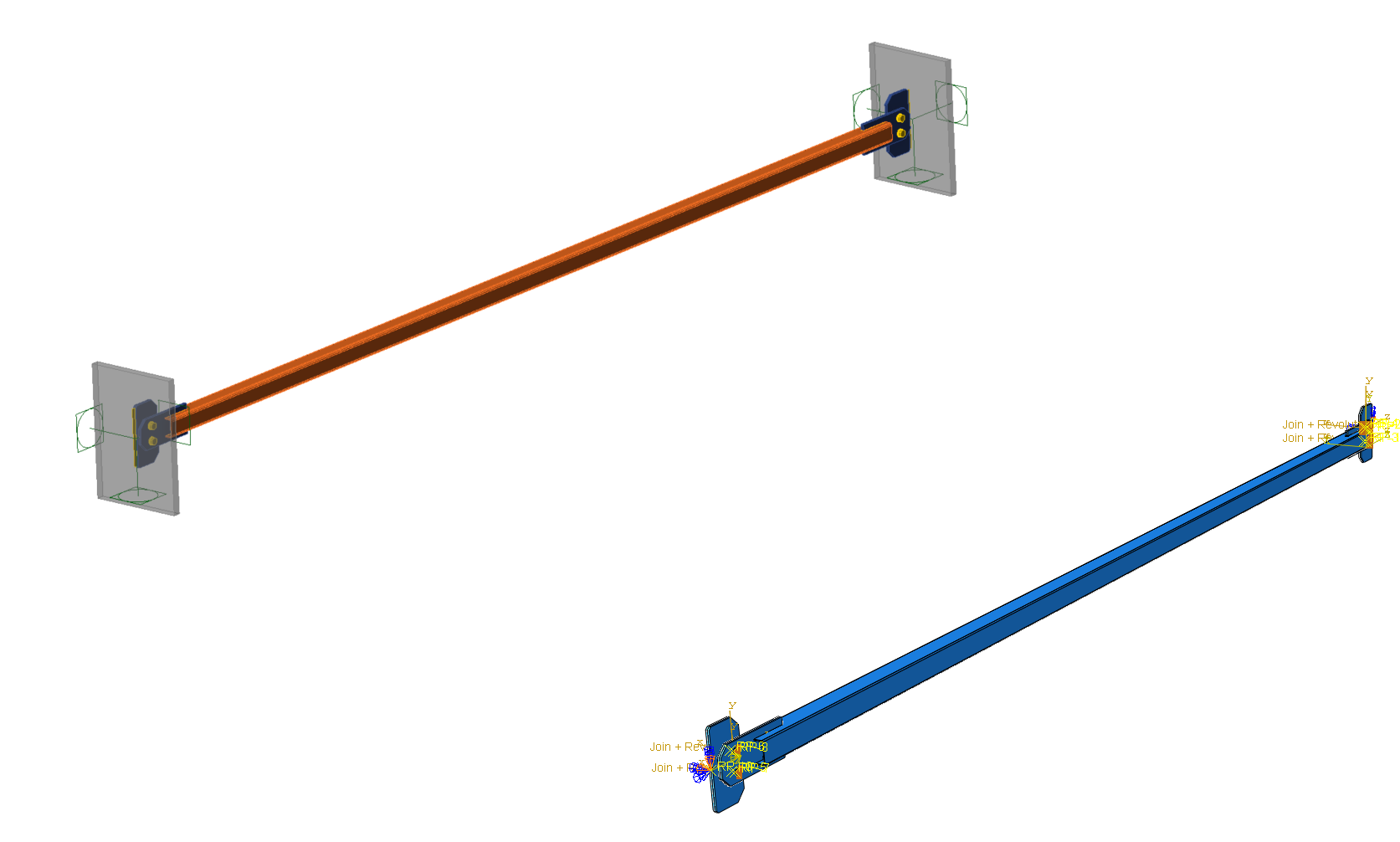
01) IDEA StatiCa-Modell (links), ABAQUS-Modell (rechts)
Netz
Für die IDEA StatiCa-Lösung wurde die Standard-Netzgröße verwendet, während ABAQUS eine Netzgröße im Bereich von 2–5 mm einsetzte.
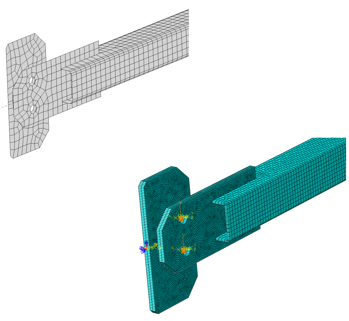
02) IDEA StatiCa-Netz (links), ABAQUS-Netz (rechts)
Last
In IDEA StatiCa wurde eine konzentrierte Druckkraft verwendet, die zunächst über die starre Auflagerbedingung verteilt wurde, während in ABAQUS eine verteilte Kopplungsgleichung mit gleichmäßiger Gewichtung eingesetzt wurde, um die konzentrierte Kraft auf alle Ränder der Platte zu übertragen. Die konzentrierte Kraft wurde anschließend zur Modellierung der Platte selbst verwendet.
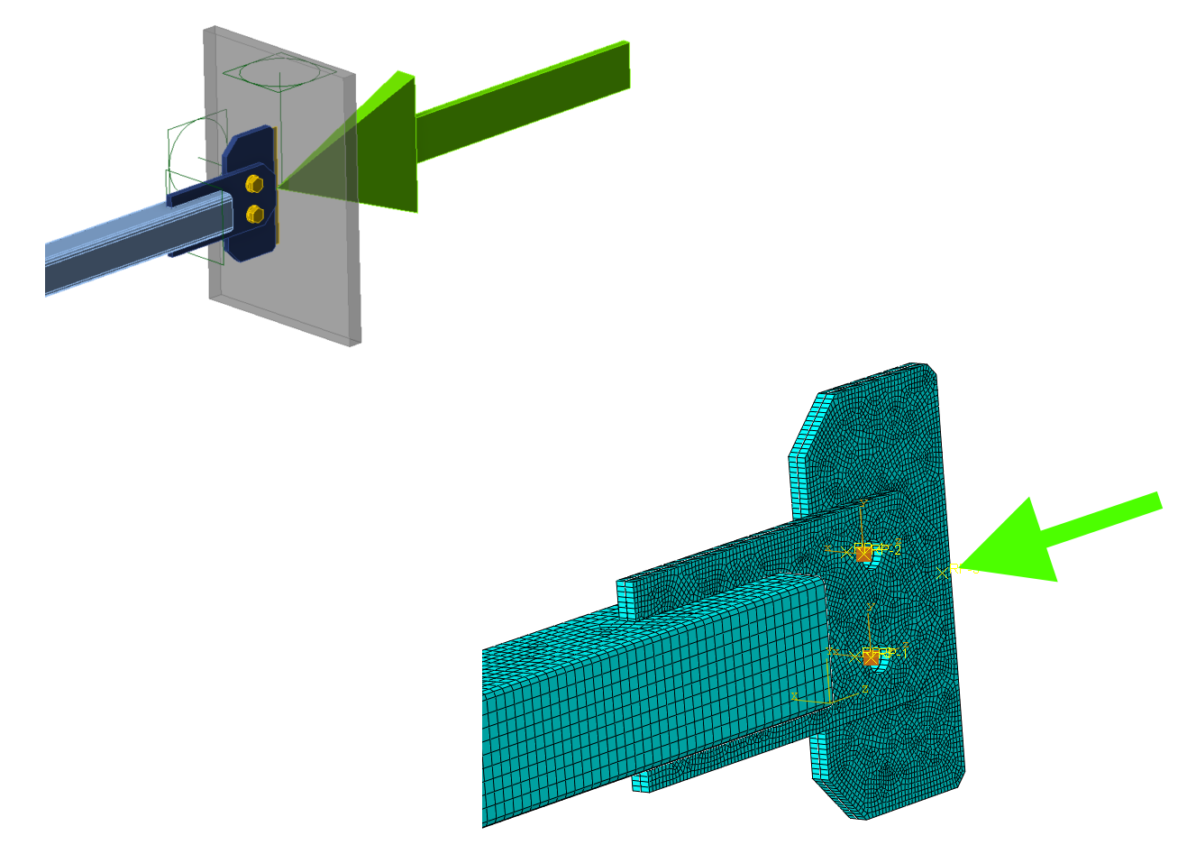
03) IDEA StatiCa-Last (links), ABAQUS-Last (rechts)
Geometrisch und materiell nichtlineare Analyse
Die geometrisch und materiell nichtlineare Analyse ist eine numerische Methode zur Simulation des Verhaltens von Strukturen unter großen Verformungen und nichtlinearen Werkstoffreaktionen. Diese Analyseart berücksichtigt die Nichtlinearitäten, die sowohl aus der Geometrie als auch aus den Werkstoffeigenschaften einer Struktur resultieren. Sie wird häufig zur Analyse von Strukturen eingesetzt, die erhebliche Verformungen erfahren, wie z. B. bei plastischen Verformungen oder großen Durchbiegungen. Die Ergebnisse dieser Analyse können Ingenieuren helfen, die Bemessung von Strukturen zu optimieren und ihr Verhalten unter verschiedenen Lastbedingungen vorherzusagen.
Das primäre Ziel der Analyse ist die Auswertung von Spannungen und Verschiebungen. Das Newton-Raphson-Verfahren wurde in jedem Inkrement eingesetzt, um das Gleichgewicht an der verformten Struktur zu ermitteln. Alle Nichtlinearitäten, einschließlich Werkstoff und Kontakte, wurden berücksichtigt.
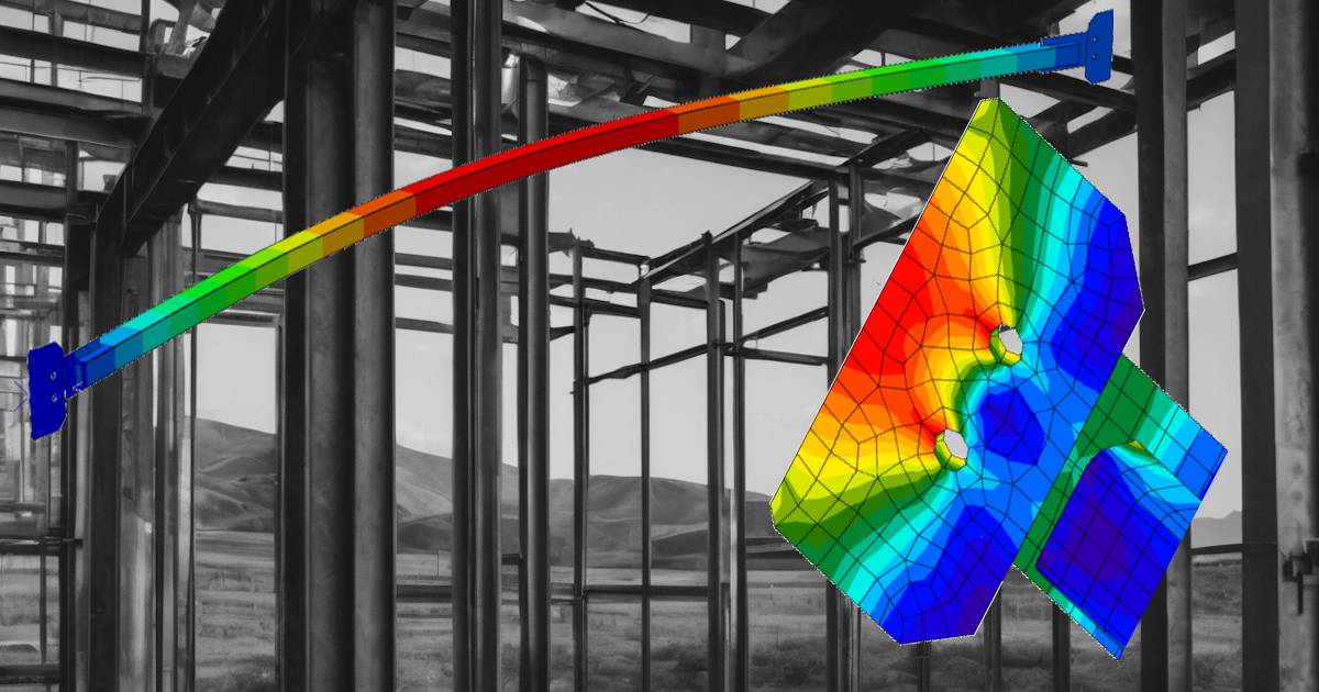
Vergleichsspannung
Die Vergleichsspannung hat in beiden Modellen die gleiche Umverteilung erreicht.
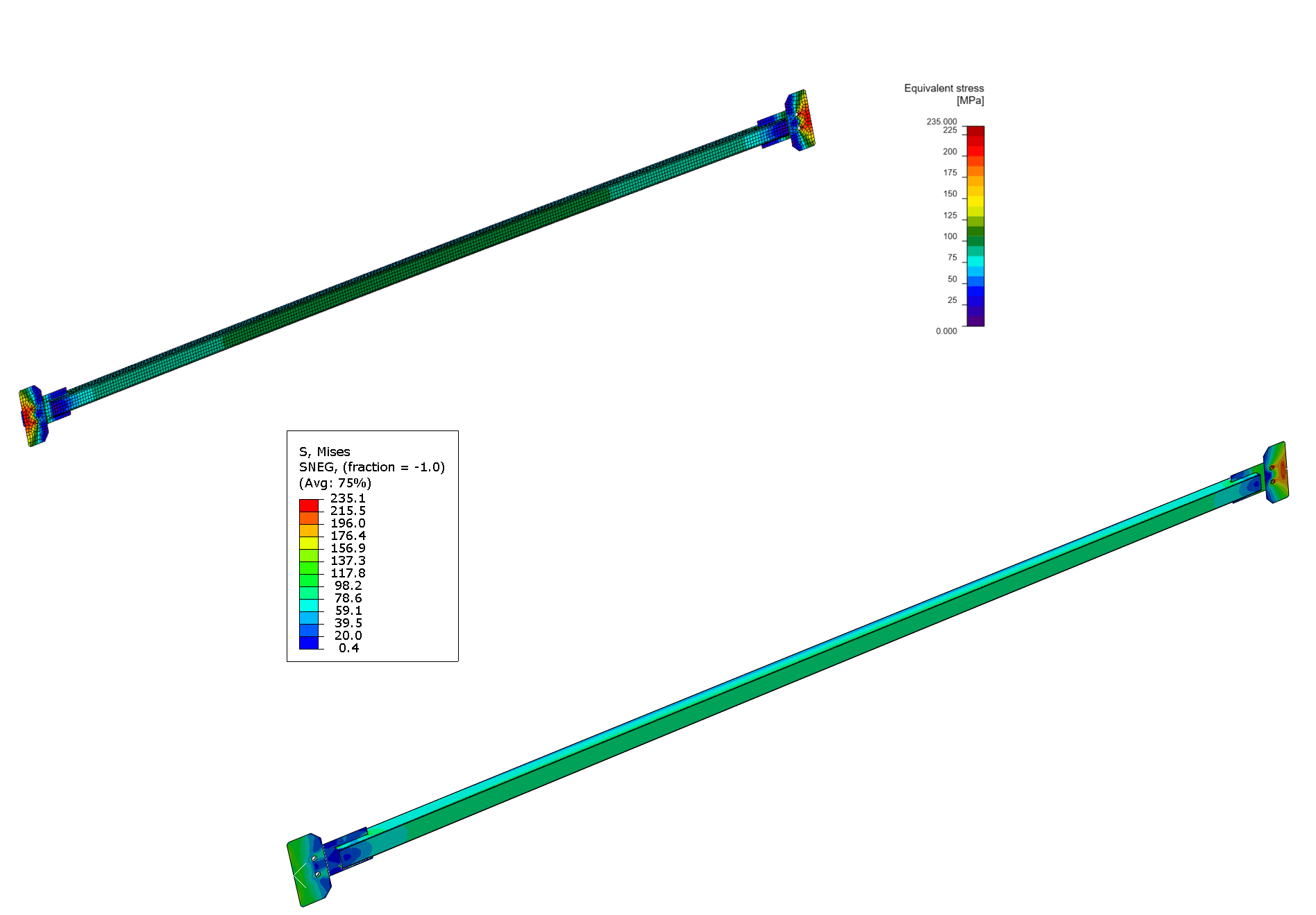
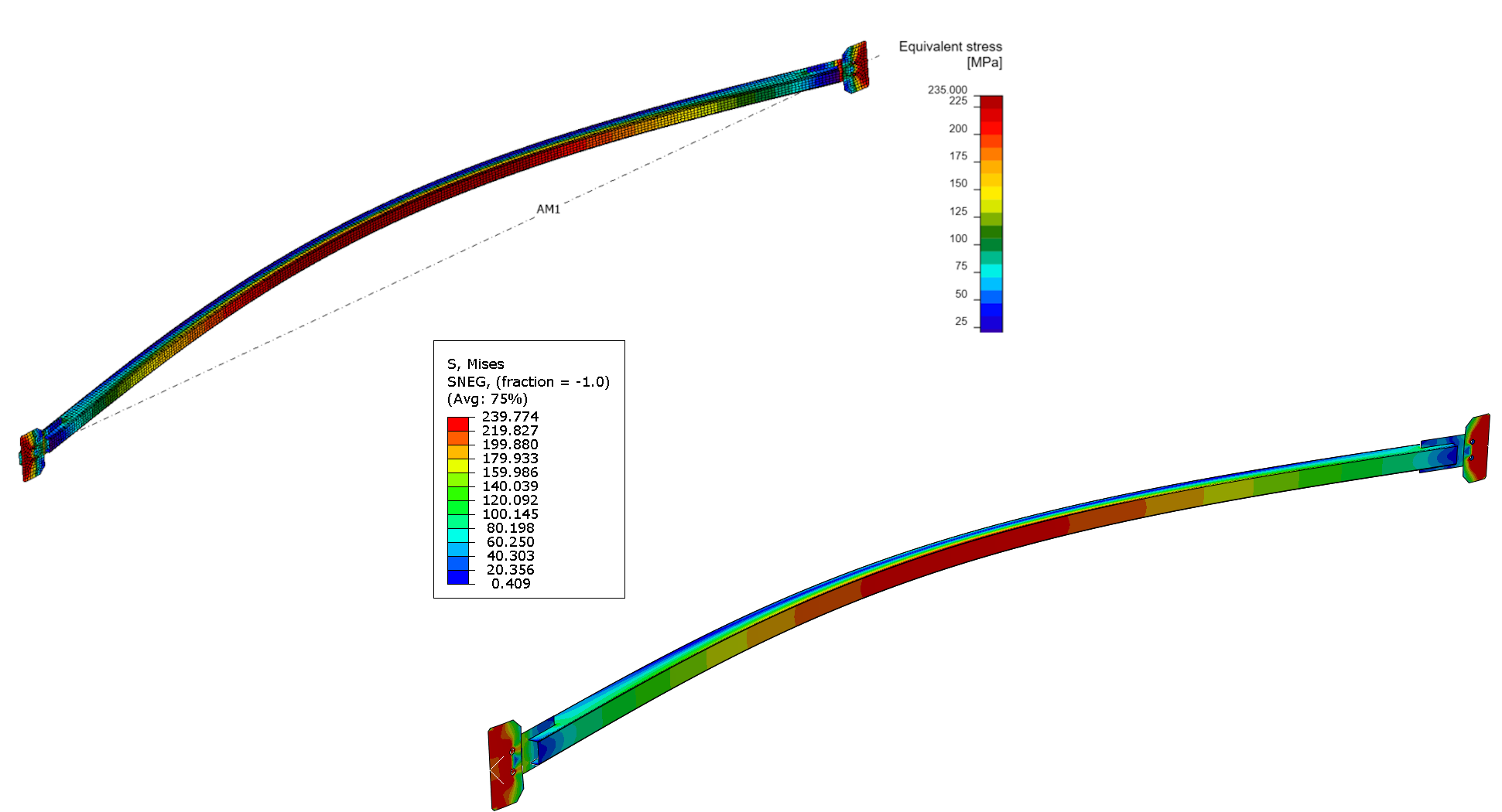
04) IDEA StatiCa Vergleichsspannung (links), ABAQUS Vergleichsspannung (rechts)
Die detaillierten Ergebnisse haben ein tieferes Verständnis der Resultate ermöglicht. Die Vergleichsspannung (VS) erreichte ihren höchsten Wert von 211 MPa in IDEA StatiCa am Integrationspunkt, während sie in ABAQUS 235 MPa betrug. Dieser Anstieg der VS in ABAQUS ist auf das feinere Netz zurückzuführen, das dazu führte, dass die Integrationspunkte näher an dem konzentrierten Spannungsbereich in der Nähe der Öffnung lagen.
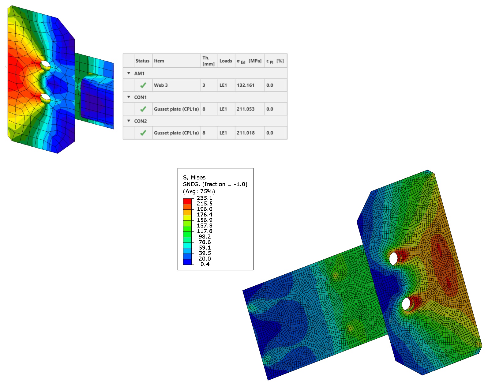
05) IDEA StatiCa Vergleichsspannung (links), ABAQUS Vergleichsspannung (rechts)
Öffnung im Kontakt
ABAQUS stellt eine zusätzliche Ausgabegröße namens „COPEN" bereit, die Informationen über den Spalt oder die Öffnung zwischen zwei Platten liefert.
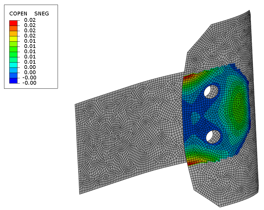
06) ABAQUS Öffnung im Kontakt
Durchbiegungen
Die Werkstoffreaktion ist elastisch, da die Spannungen nur den lokalen Bereich nahe der Fließgrenze der Öffnung beeinflussen. Die Durchbiegungen zeigen eine sehr gute Übereinstimmung der Ergebnisse.
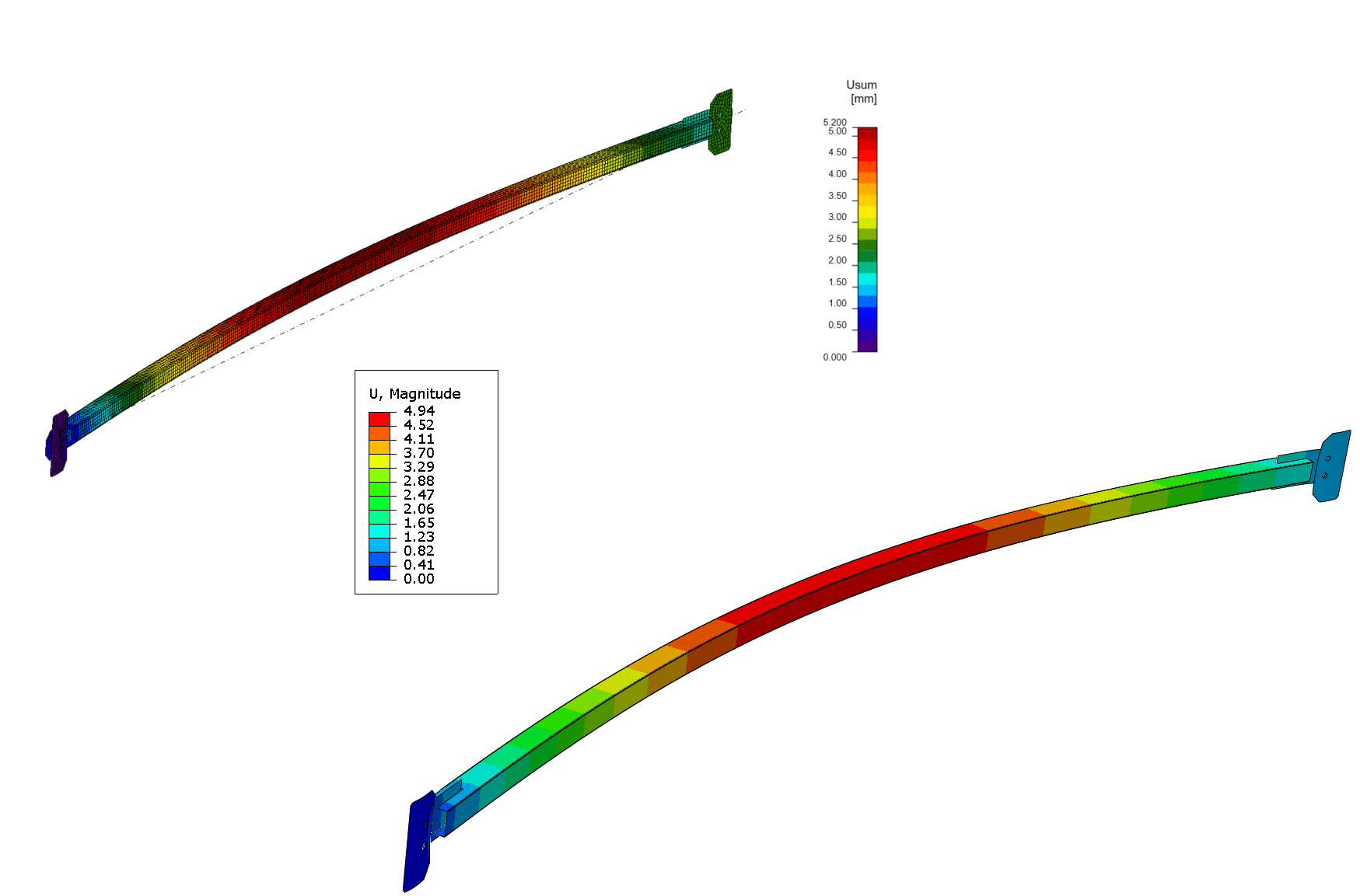
07) IDEA StatiCa Gesamtverformung (links), ABAQUS Gesamtverformung (rechts)
Lineare Beulanalyse
Die lineare Beulanalyse ist eine numerische Methode zur Vorhersage der Stabilität und des Beulverhaltens von Strukturen unter aufgebrachten Lasten. Sie umfasst die Bestimmung der kritischen Last oder des Lastfaktors, bei dem eine Struktur instabil wird und Beulen auftritt. Diese Analyse hilft Ingenieuren, die Tragwerkssicherheit und Bemessung verschiedener Bauteile wie Stützen, Träger und Schalen zu beurteilen.
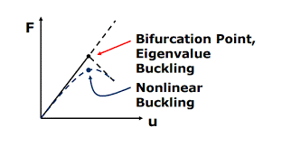
08) Lineares vs. nichtlineares Beulen
Einer der bedeutendsten Beiträge der linearen Beulanalyse ist die Erzeugung von Eigenformen und kritischen Lastfaktoren, die Tragwerksplanern helfen, potenzielle Tragwerksversagen vorherzusehen und zu verhindern. Basierend auf der Verifikation ist eine Übereinstimmung zwischen IDEA StatiCa und ABAQUS mit sehr geringer Abweichung erkennbar. Die erste Beulform des Bereichs hat einen kritischen Faktor von 1,64 gegenüber 1,57 in ABAQUS erreicht.
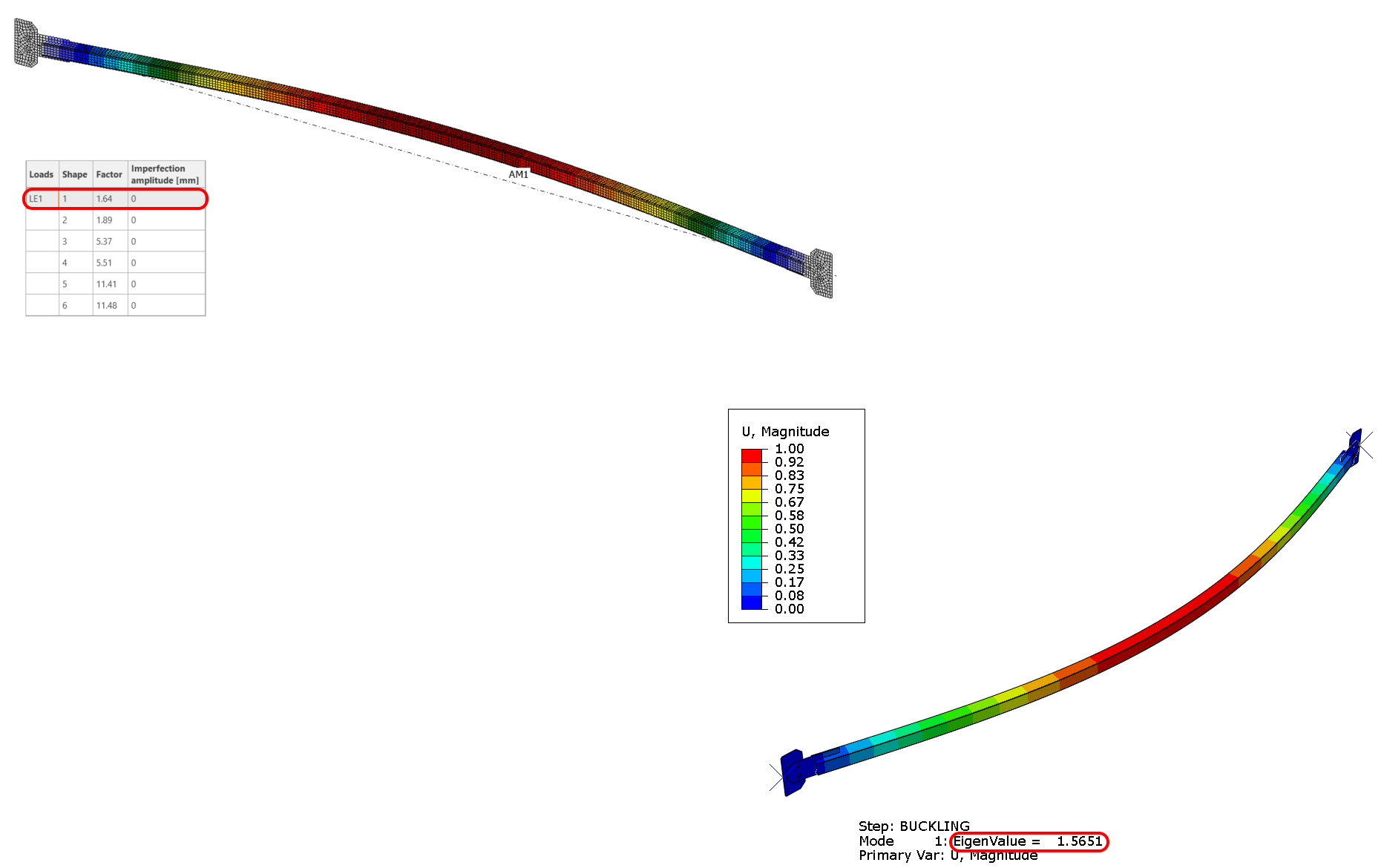
09) IDEA StatiCa erste Beulform (links), ABAQUS erste Beulform (rechts)
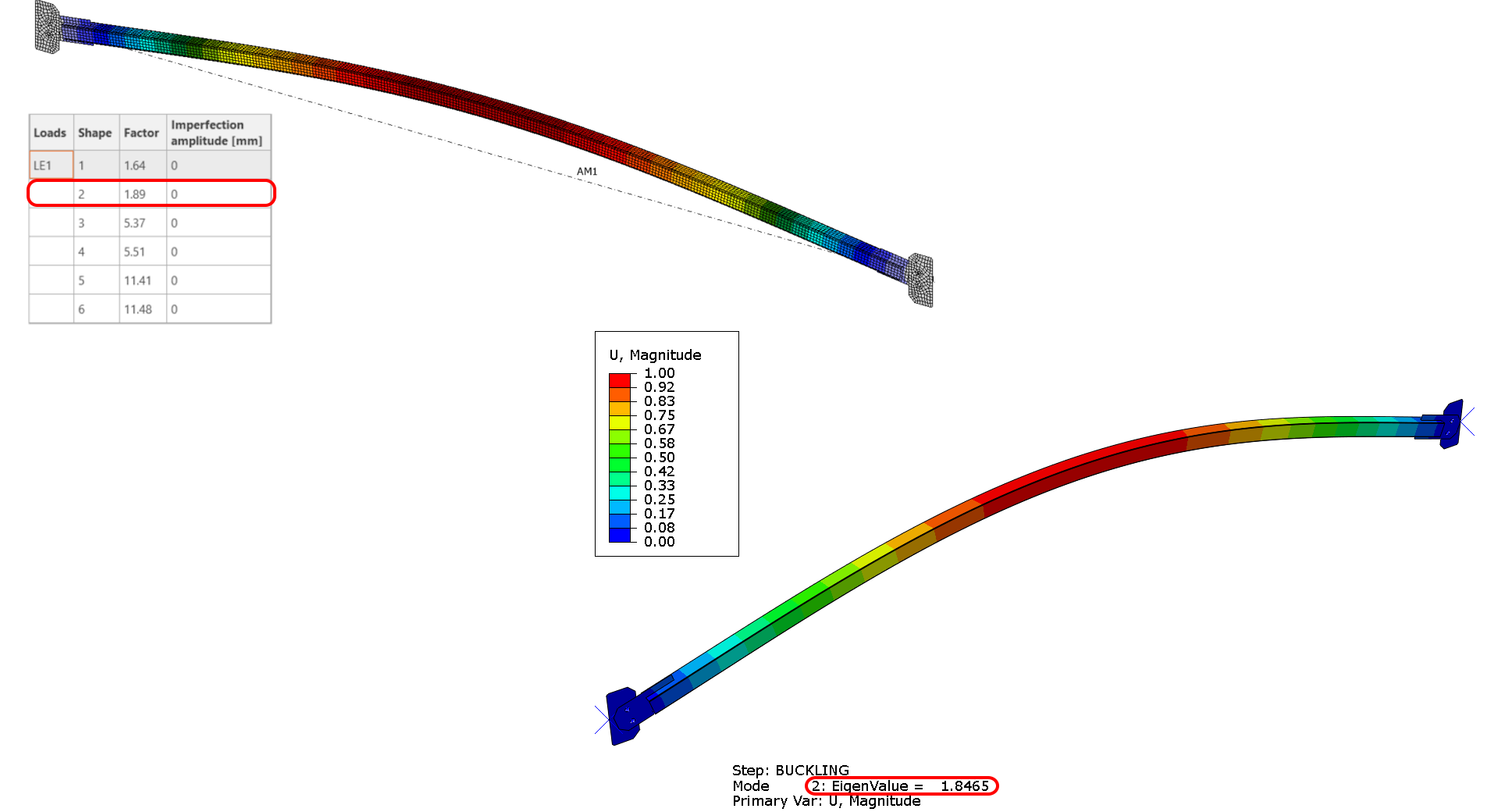
10) IDEA StatiCa zweite Beulform (links), ABAQUS zweite Beulform (rechts)
Imperfektionen
Gemäß EN 1993-1-1 ist die Berücksichtigung von Imperfektionen für die Integrität jeder Analyse unerlässlich. Die lokalen Imperfektionen hängen von der Knickspannungslinie gemäß Tabelle 6.1 und der Querschnittsklassifizierung ab. Angesichts der Einordnung des SHS 50/50/3 unter Knickspannungslinie C beträgt die entsprechende lokale Imperfektion 14 mm.
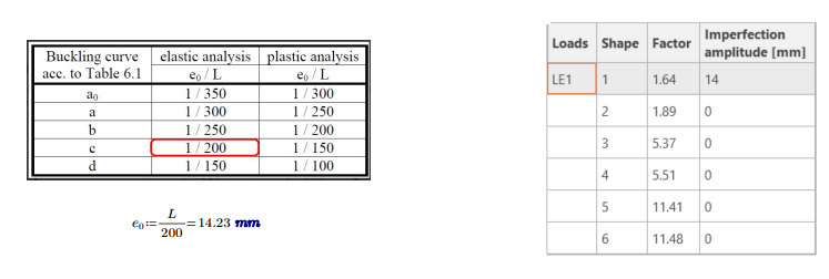
11) Imperfektionswerte
Geometrisch und materiell nichtlineare Analyse mit Imperfektionen
Die geometrisch und materiell nichtlineare Analyse (GMNIA) ist eine in der Ingenieurpraxis eingesetzte Analysemethode zur Untersuchung des Verhaltens von Strukturen unter extremen Lasten. Diese Analyse berücksichtigt sowohl die geometrische Nichtlinearität (Formänderungen) als auch die materielle Nichtlinearität (Änderungen der Werkstoffeigenschaften) einer Struktur sowie etwaige anfängliche Imperfektionen oder Verformungen. Durch die Berücksichtigung dieser Faktoren können Ingenieure besser verstehen, wie sich eine Struktur unter Belastung verhält, und fundierte Entscheidungen über ihre Bemessung und Sicherheit treffen.
Die Analyse sucht in jedem Inkrement das Gleichgewicht unter Verwendung der anfänglichen verformten Gestalt aus der Imperfektion der linearen Verzweigungsanalyse (LBA). Kann kein Gleichgewicht gefunden werden, wird die Berechnung abgebrochen.
- Materielle Nichtlinearität – tritt auf, wenn der Werkstoff sich nicht mehr elastisch verformen kann und beginnt, plastisch zu fließen, was eine Änderung seines Verhaltens bewirkt.
- Stabilitätsprobleme – entstehen, wenn die Struktur aufgrund fehlenden Gleichgewichts keine weiteren Iterationen durchführen kann und ein Verzweigungspunkt erreicht wurde.
Die von IDEA StatiCa verwendete Methode zur Lösung des Gleichgewichts basiert auf dem Newton-Raphson-Verfahren. Die Analyse wird beim Erreichen des Lastmaximums beendet, und der absteigende Ast bleibt ungelöst. Dies wird jedoch für Tragwerksplaner nicht als notwendig erachtet, da deren primäres Interesse einer stabilen Lösung gilt und nicht einer instabilen.
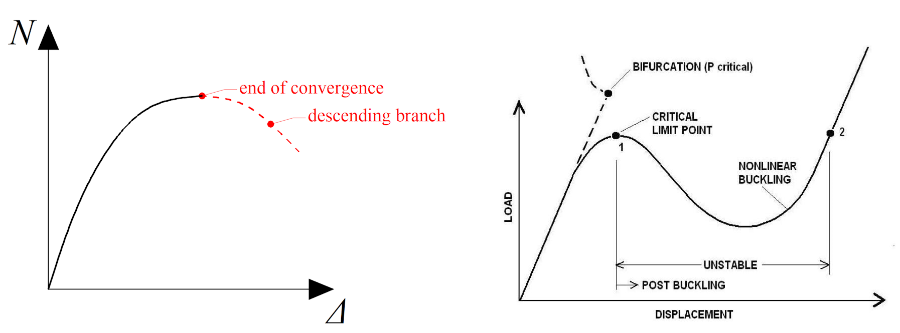
12) Last-Verformungs-Kurve IDEA StatiCa (links), ABAQUS (rechts)
Der Ausgangszustand für die GMNIA basiert auf der aus der Beulanalyse abgeleiteten Form. In unserem Fall ist die erste Eigenform eine halbsinusförmige Welle.
Vergleichsspannung
Die Spannungsniveaus sind erheblich angestiegen und nähern sich der Fließgrenze. Dies zeigt an, dass bestimmte Bauteile kurz vor dem Fließen stehen, wodurch sich das IDEA StatiCa-Modell in einem plastischen Zustand befindet.
13) IDEA StatiCa Vergleichsspannung (links), ABAQUS Vergleichsspannung (rechts)
Plastische Dehnung und plastische Bereiche
Die Stellen, an denen das Fließen begonnen hat, traten im Bereich der Verbindung und in der Mitte der Aussteifung selbst auf.
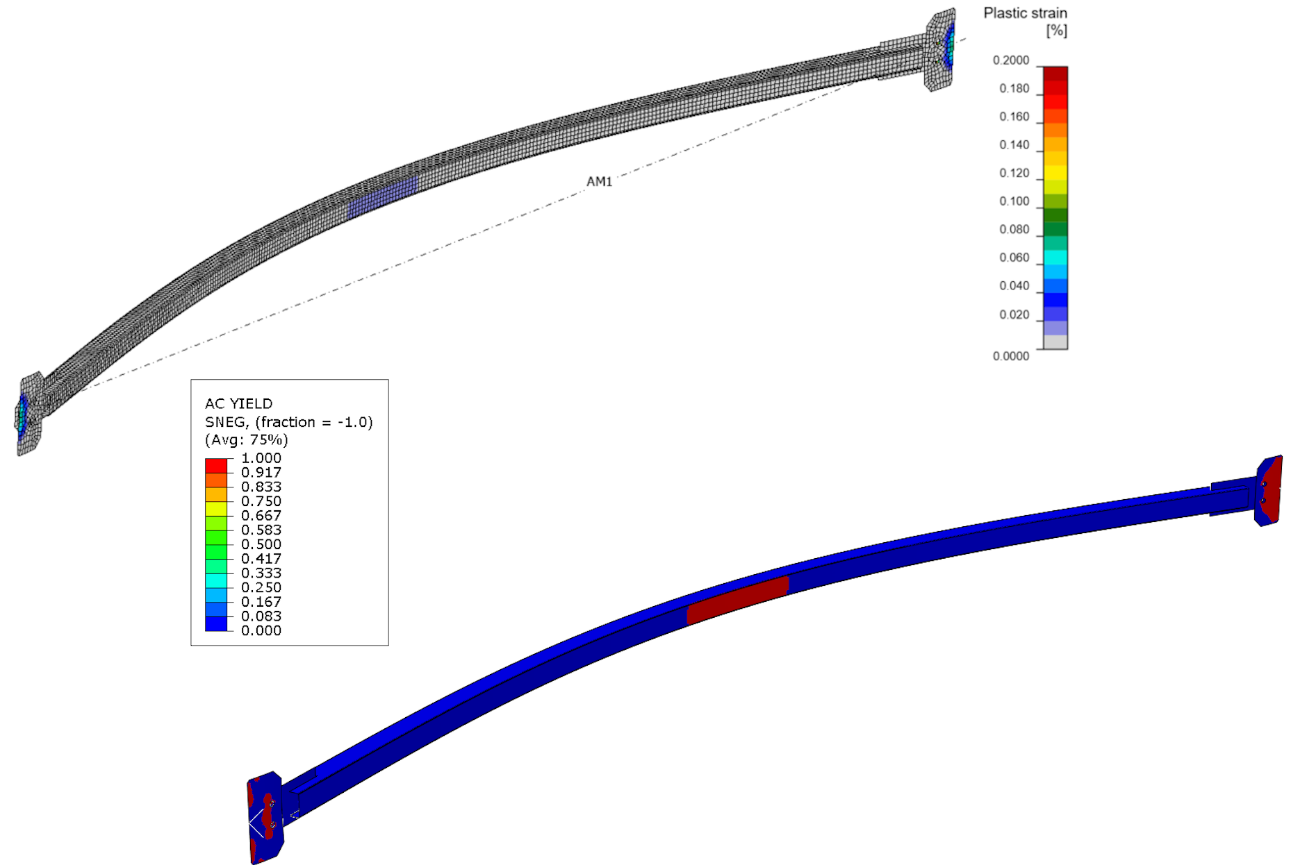
14) IDEA StatiCa plastische Dehnung (links), ABAQUS plastische Dehnung (rechts)
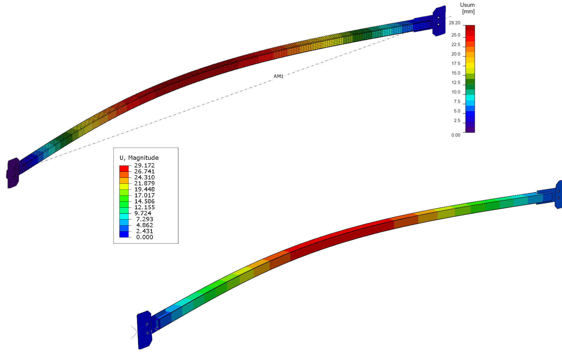
Verformung
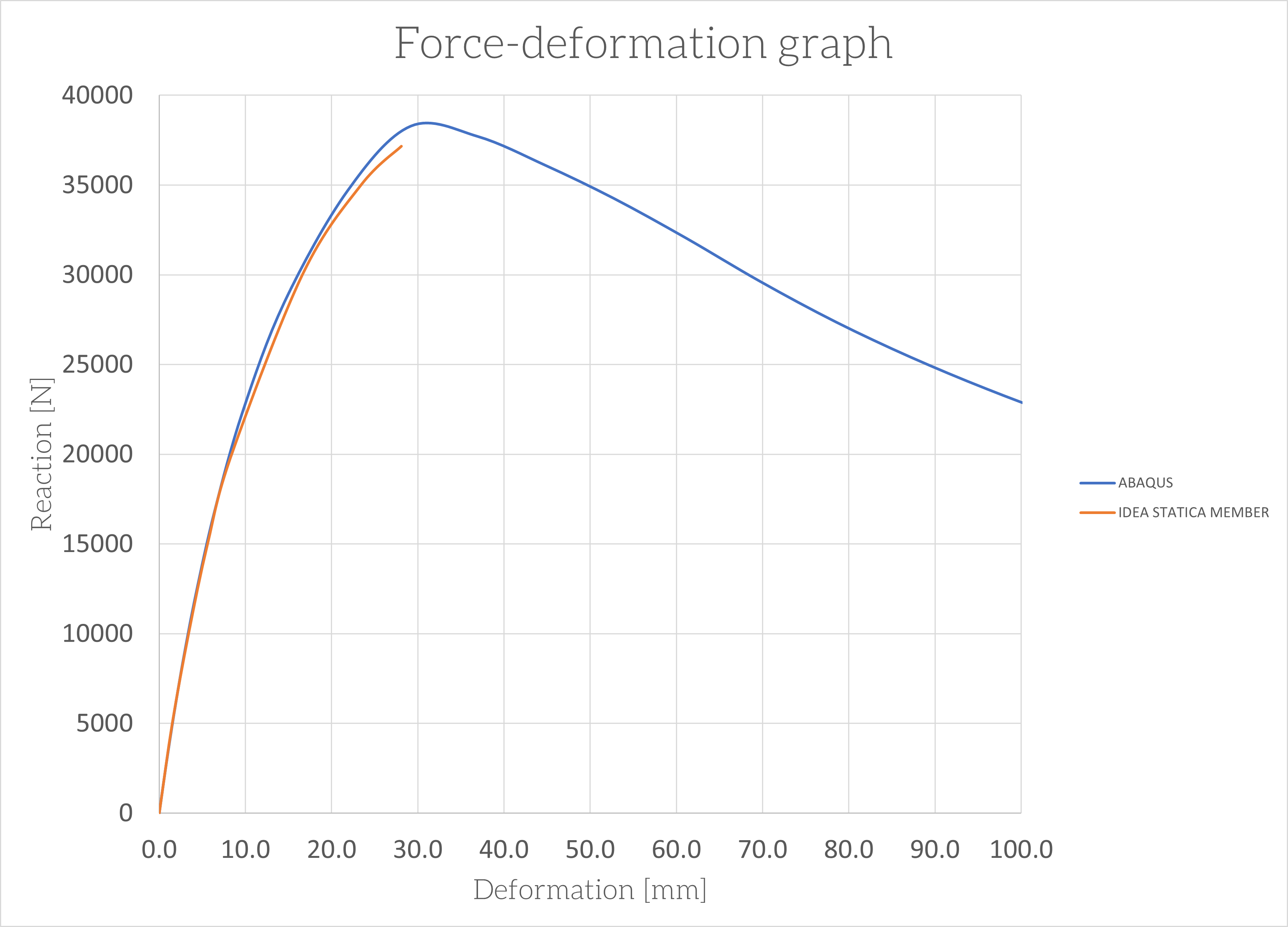
Kraft-Verformungs-Diagramm
Fazit
Im Rahmen des Verifizierungsprozesses bestand das Hauptziel darin, die Leistungsfähigkeit von IDEA StatiCa Member bei der sicheren Bemessung und dem Normnachweis verschiedener Strukturen zu demonstrieren. Das Werkzeug wurde eingehend getestet und bewertet, um seine Wirksamkeit bei der Lieferung genauer Ergebnisse unter Einhaltung der Branchenstandards zu bestimmen. Die Verifikation zielte darauf ab, ein umfassendes Verständnis der Funktionen und Vorteile des Werkzeugs zu vermitteln, einschließlich seiner Fähigkeit, den Bemessungsprozess zu optimieren und Fehler zu reduzieren. Im Rahmen des Verifizierungsprozesses bestand das Hauptziel darin, die Leistungsfähigkeit von IDEA StatiCa Member bei der sicheren Bemessung und dem Normnachweis verschiedener Strukturen zu demonstrieren. Das Werkzeug wurde eingehend getestet und bewertet, um seine Wirksamkeit bei der Lieferung genauer Ergebnisse unter Einhaltung der Branchenstandards zu bestimmen. Die Verifikation zielte darauf ab, ein umfassendes Verständnis der Funktionen und Vorteile des Werkzeugs zu vermitteln, einschließlich seiner Fähigkeit, den Bemessungsprozess zu optimieren und Fehler zu reduzieren.
Der Vergleich zwischen der analytischen Lösung und IDEA StatiCa Member sowie der ABAQUS-Lösung ergab eine 95%ige Übereinstimmung der Ergebnisse. Der maximale Bemessungswert, der während des Bemessungsprozesses ermittelt wurde, betrug 35,8 kN. Der kritische Bemessungswert stieg jedoch auf 37,1 kN bei Verwendung von IDEA StatiCa Member, während ABAQUS einen Maximalwert von 38,2 kN anzeigte. Diese Ergebnisse sind bemerkenswert, da sie die Wirksamkeit dieser Bemessungsansätze bei der Erzielung genauer Resultate belegen.
Die Ergebnisse für Vergleichsspannung, Plastizität und Verformungen sind über verschiedene Anwendungen hinweg konsistent, was die Zuverlässigkeit der Normauswertung belegt. Diese Ergebnisse demonstrieren die Genauigkeit und Robustheit des Verfahrens bei der Vorhersage des Systemverhaltens. Ihre Konsistenz macht das Verfahren sowohl für den gewerblichen als auch für den akademischen Einsatz geeignet.
Präzision auf Knopfdruck – IDEA StatiCa 14 Tage kostenlos testen
