
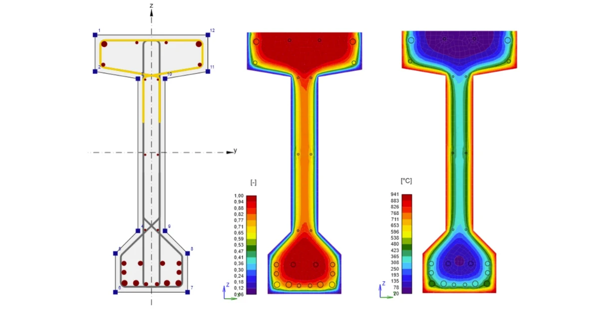
First, we’ll unpack the new edition so you can approach it with confidence. Then, we’ll put the second option into practice on a real precast girder, showing how easily the process can be automated. (Clause numbers refer to EN 1992-1-2:2023 unless marked 2004.)
What changed in the standards - Fire resistance
1. The tables stay – but the rules around them get tighter.
Tabulated data remains the quick and conservative route, while calculation methods are there for members the tables cannot cover. The 2023 edition keeps this approach but clarifies the boundaries: tabulated results are generally considered safe-sided relative to tests and to simplified or advanced methods, and extrapolation beyond the stated range is not allowed (cl. 6.1(2)).
The goal is also to make the three approaches work together more consistently. The foreword confirms that the tabulated provisions were updated to align the tabulated, simplified, and advanced methods.
What are the tables calibrated to?
The minimum dimensions in the tables are based on fixed assumptions. The key reference values remain largely unchanged:
- ηfi = 0.7 — the reference load level (2004, cl. 5.2(3); 2023, cl. 6.2(1)).
- 500 °C — the critical reinforcement temperature for simply supported members in bending, corresponding to around 0.60 fyk at ηfi = 0.7 and γS = 1.15 (2004, 5.2(4); 2023, cl. 6.2(3), Note 1).
There are, however, two notable changes:
- Thermal conductivity: the 2004 edition allowed the data to be used across the permitted range of thermal conductivity. The 2023 edition provides a single thermal conductivity function.
- ηfi: in 2004, a National Annex could modify this value (2004, 5.2(3), Note). In 2023, ηfi = 0.7 is fixed in cl. 6.2(1).
The same clause also requires tabulated data to be corrected when the basic assumptions do not apply, and excludes their use where material factors have been modified under Annex A of EN 1992-1-1.
2. Moisture content is no longer just a percentage – it is now part of the decision process.
The basic principle remains the same in both editions: severe spalling must be avoided, or its effect on performance must be taken into account.
But the way moisture is treated has changed:
- 2004: explosive spalling was linked to a moisture threshold expressed as a percentage by weight, with the recommended value set by the National Annex.
- 2023: the fixed percentage is gone. Moisture content is now considered alongside other factors that can influence spalling, including exposure, load, restraint, geometry, aggregate, additions, air content, fibers, permeability, and strength.
The 2023 edition also introduces a dedicated decision table (Table 10.1). It links the assessment to four key inputs: fire resistance period, moisture condition, concrete strength, and silica fume content.
In other words, moisture is no longer a single number to check — it is one piece of a broader spalling assessment.
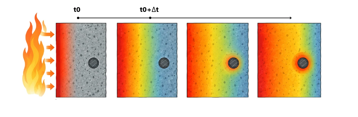
3. The 500 °C isotherm is gone – and temperature graphs make way for formulae.
The 2004 edition offered two reduced cross-section methods in informative Annex B, the 500 °C isotherm method and the zone method (2004, 4.2.3, B.1.1(3) to (4), B.2(3)). The 2023 text contains no 500 °C isotherm method, and its clause 7.3.2 uses the zone-method logic only.
Why results change through Part 1-1 – EN 1992-1-2 is written as a supplement to normal temperature design. It identifies differences from or additions to EN 1992-1-1 and cites the 2023 edition of that standard as a dated normative reference (cl. 1.1(1)).
This link is particularly clear in the simplified bending check:
- MRd,fi is valid unless As,prov/As,req > 1.3 (cl. 7.3.3.2, Formula 7.18).
- Both MEd and As,req come from EN 1992-1-1.
- The 2023 method averages the temperature-reduced strength over the individual tension bars.
What else has changed?
EN 1992-1-1 itself changed. The second generation brings revised rules for shear and torsion, a wider scope covering bridges, liquid-retaining and containment structures, CFRP strengthening, and steel fiber-reinforced concrete, plus new annexes for assessing and strengthening existing structures.
Shear and torsion move from an informative annex into the main text. In 2004, the calculation method for shear, torsion and anchorage sat in informative Annex D, which carried a note that shear failures due to fire are very uncommon and that the methods given were not fully verified (2004, Annex D). The 2023 edition places shear and torsion in clause 7.3.5, within the simplified design methods, and moves anchorage to the detailing rules, where fire anchorage and lap lengths may be taken equal to the ambient values (cl. 9.2(1)).
The tabulated route is unchanged in this respect. When the minimum dimensions of clause 6 are followed, further checks for shear, torsion and anchorage may be omitted (cl. 6.1(7); 2004, 5.1(3)). The change concerns members verified by calculation. Clause 7.3.5 separates two cases:
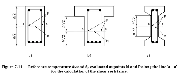
- Members with shear reinforcement (cl. 7.3.5.3). The reduced section of cl. 7.3.2 applies, and concrete strength is taken at point M. The strength of the links is reduced using the temperature at point P, the intersection of the link with the section at mid-depth of the web. (See the picture below) The shear methods of EN 1992-1-1 are then applied to the reduced section. In flat slabs, vertical links or studs count only where they intersect the control failure surface in the reduced geometry, and torsion follows the same logic (cl. 7.3.5.3(6), 7.3.5.4).
- Members whose shear strength depends on concrete tensile strength (cl. 7.3.5.2). Prestressed members and plain or lightly reinforced members need special consideration of the tensile stresses caused by nonlinear temperature distributions, for example in voided slabs and thick beams. Tensile strength is otherwise ignored, and where it is used, the reduction follows Formulae (5.21) and (5.22) (cl. 5.3.1.2).
New edition, new structure: where to find what you need
| EN 1992-1-2:2004 | EN 1992-1-2:2023 |
| 4.2 Simplified calculation method | 7 Simplified design methods |
| 4.3 Advanced calculation methods | 8 Advanced design methods |
| 4.5 Spalling | 10 Rules for spalling |
| 5 Tabulated data | 6 Tabulated design data |
| 6 High-strength concrete | No standalone section. Table 5.1 has a column for fck ≥ 70 MPa, with limits in 6.1(5) and section 10. |
| Annex A Temperature profiles (informative) | 7.2 Temperature profiles |
| Annex B.1 500 °C isotherm method | No equivalent |
| Annex B.2 Zone method | 7.3.2 Reduction of cross-section |
| Annex C Buckling of columns (informative) | Annex D, now normative, and 6.3.3 |
| Annex D Shear, torsion and anchorage (informative) | 7.3.5 Shear and torsion; anchorage in 9.2 |
| Annex E Simplified calculation method for beams and slabs (informative) | 7.3.3 Bending |
And then there’s the new stuff
- National choice reduced – The 2004 foreword lists sixteen clauses open to national choice. The 2023 foreword lists three clauses. No longer national choices: the conductivity range, the moisture threshold, the Method A eccentricity limit, the reference load level ηfi, and the decision on whether advanced methods may be used. (2023 0.5; 2004 foreword, 3.3.3, 4.1, 4.5.1, 5.2(3), 5.3.2)
- Method A, eccentricity – First-order eccentricity in fire is limited to a quarter of the section dimension and is fixed in the standard. The 2004 recommended value was 0.15h. (2023, 6.3.2.2(2)b; 2004, 5.3.2(2))
- Cooling phase – Formulae give the strength of concrete heated to a peak temperature and cooled back to 20 °C. The 2004 text only said that a possible strength gain in cooling should not be counted. (2023, 5.3.1.1(5), 4.3(1); 2004, 3.2.2.1(7))
The IDEA StatiCa approach: section check today and the future
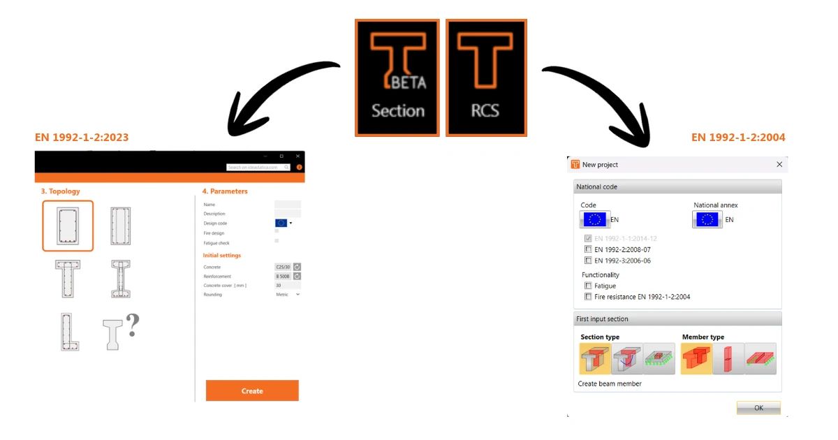
What RCS covers
IDEA StatiCa RCS application answers one question quickly: does a section pass the tabulated data? That boundary is worth stating precisely, because it is where the second generation separates the tabulated route from the calculation routes. Fire resistance in RCS is available for slabs, walls, beams, columns, and slender columns. The functionality is selected in the project wizard as Fire resistance EN 1992-1-2:2006-11.
- Columns – Method A and Method B
- Beams – Rectangular, T-section and I-section only. Single-span or continuous beams must be distinguished, and for a continuous beam the position of the section along the beam must be set, which has a significant impact on the check. The checked values are the web width and the distance from the outer reinforcement layer to the nearest exposed surface.
- Slabs – One-way and two-way slabs, a continuous plate supported by walls and a continuous plate supported by columns.
- Walls – Load-bearing walls and non-load-bearing walls
Why rely on tables when you can calculate the actual temperature?
Tables are a quick way to check fire resistance, but they only cover specific section shapes, dimensions, axis distances, and fire conditions.
That works for new designs, where you can adjust the section if it fails. But for existing members, the geometry is already fixed — and a section that misses the table by just a few millimeters has no table-based solution.
This is where calculating the actual temperature field makes a difference. Instead of relying on predefined values, you can calculate how heat spreads through the real section and use those temperatures to check its capacity. The Section app does exactly that — analyzing the actual section and reinforcement layout, then checking its fire resistance based on the calculated temperatures.
What the new Section application adds
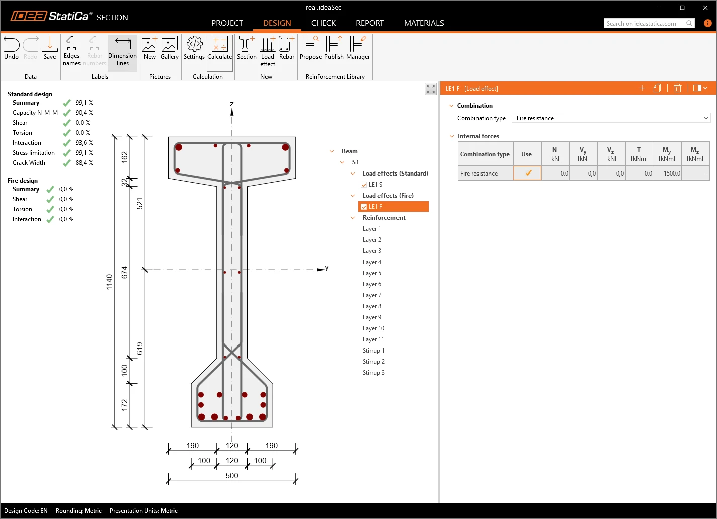
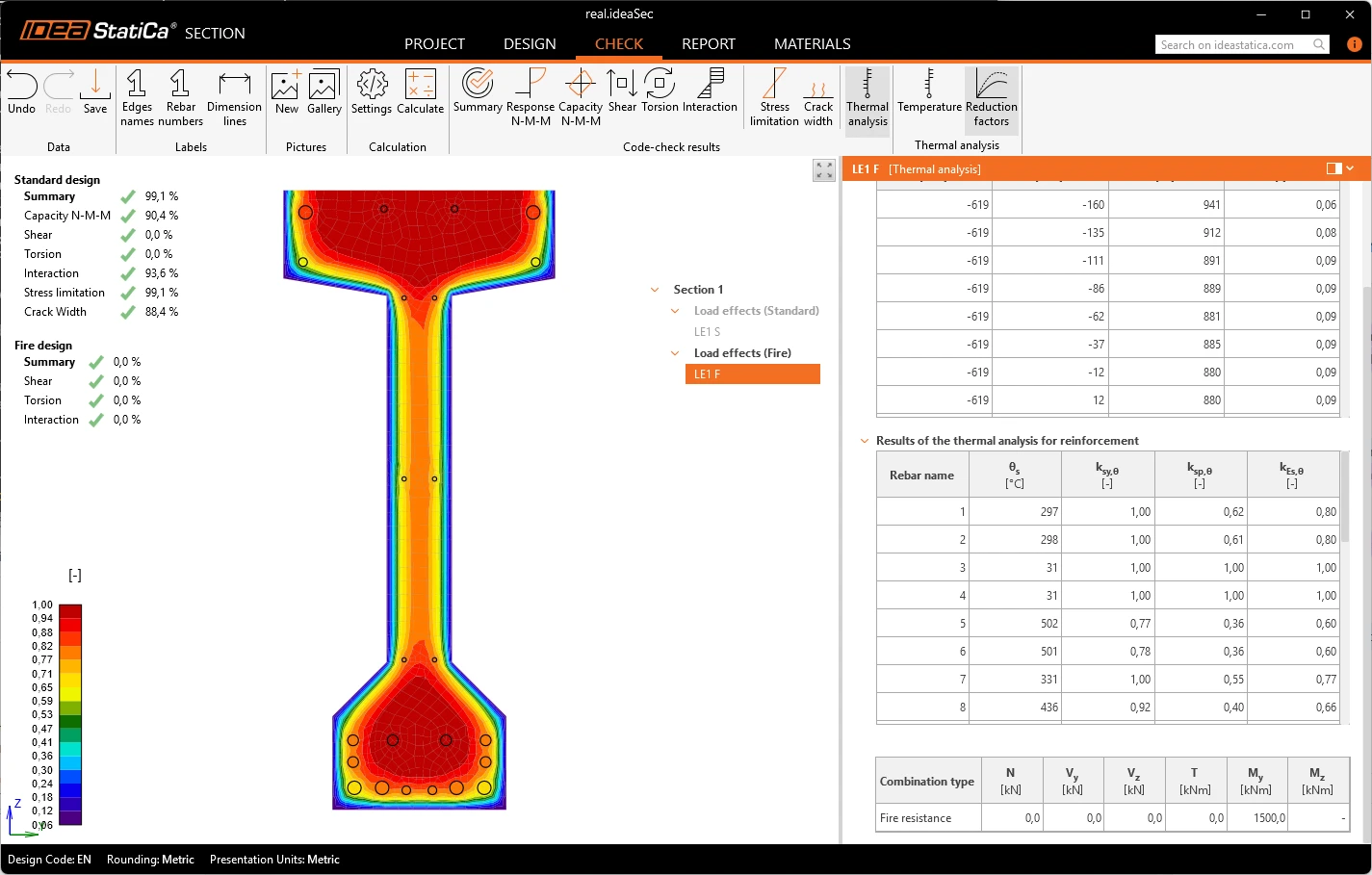
See an example of a roof girder in Section. A table check gives a yes-or-no for one-axis distance. Using the Section app, the same section returns a utilization. To see what the advanced method looks like on a real member, we ran a roof girder through the Section app (BETA). The fire situation is switched on in the same project as the normal-temperature checks, so there is no second model. The fire load effects are entered as a separate group, distinct from the ULS and SLS effects, because the internal forces in a fire differ from those at normal temperature.
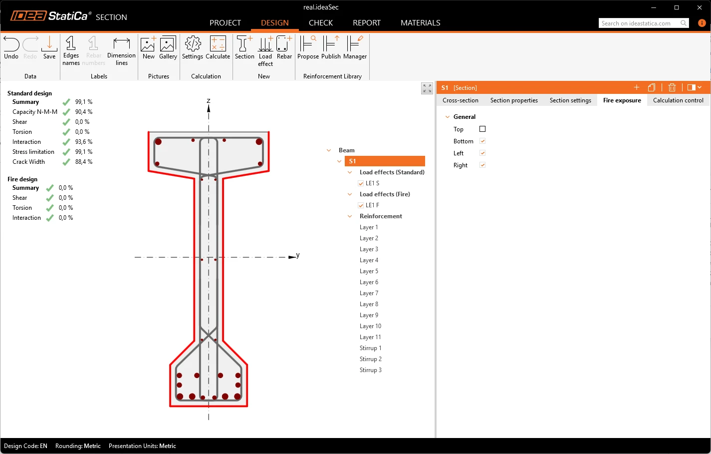
The modeled section is a 1140 mm-deep precast I-girder with multiple bar diameters and a layout optimized for the manufacturer’s needs. The fire resistance class is R60; the fire curve is the standard fire curve in EN 1991-1-2; and the sides exposed to fire are the bottom, left, and right. The user picks the exposed sides from four options (top, bottom, left, right – see the pictures below), and the application derives the actual exposed edges, drawn in red, including on re-entrant corners such as web-to-flange junctions. The section is the middle section, and its loading in the showcase is by bending moment only.
Temperature distribution – The application meshes the section with a finer mesh and calculates the temperature field in time steps up to 60 minutes (60 minutes in this case, up to 240 minutes overall). In the heatmap, the soffit and the lower corners are the hottest, and the temperature falls steeply toward the web center. The data view lists the temperature of concrete elements and of each individual bar. For example, the lowest corner bar reaches 480 °C, while the bars at the upper flange middle are almost at room temperature. A table cannot show this spread; it works with a single nominal axis distance.
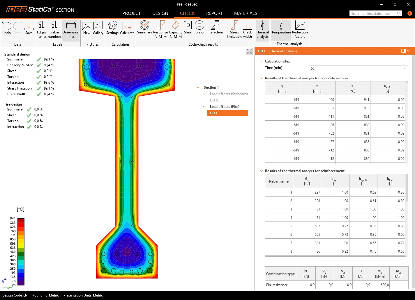
From these temperatures, the application derives the reduced material properties using reduction factors for concrete strength, reinforcement yield and proportional limit, and the modulus of elasticity. It uses the reduction factors of EN 1992-1-2. The factor map shows what actually governs the check. In this girder, the lowest bar retains 60% of its yield strength, and the concrete in the bottom-flange corners retains about 6% of its strength. Last but not least, the Section app uses formulas to make it easy to navigate the outcome. For example, the bending check is the same response as at normal temperature, now evaluated with the reduced strengths.
Conclusion
Whether an engineer reads the second generation of EN 1992-1-2 directly or lets the software do the work, the starting point is the same. Tabulated data remain the quick, safe-sided check for new, regular members. For those working through the standard, the changes covered above show where the 2023 rules differ from the 2004 edition. When the table fails or does not apply, the standard points to advanced calculation methods, and the Section app runs that route: it derives the temperature of each bar and concrete element, applies the reduced material properties, and returns a utilization instead of a pass/fail. Because it reflects the section's actual behavior, it is a convenient, quick, and precise alternative to the tabulated route.