Rotational stiffness – the direct stiffness approach
Motivation
Having a deep understanding of Finite Element Analysis (FEA) is crucial for both ensuring accurate inputs and presenting the results in the right way. The main objective of this article is to explain how the matrix is assembled in the background of every FEA software and how rotational stiffness can influence the global behavior of a structure. This article serves as a prerequisite for an upcoming article, where all the findings will be applied to a structure using IDEA StatiCa Connection.
The direct stiffness approach – rigid connections
Let's take a look at the simple example of a structure shown in figure 1. The structure consists of a column and a beam with identical cross-section HEA 200 properties. Each node has three degrees of freedom, including two translations (X and Z) and one rotation (Ry). The workspace is 2D. The material is steel with a modulus of elasticity of 200,000 MPa.
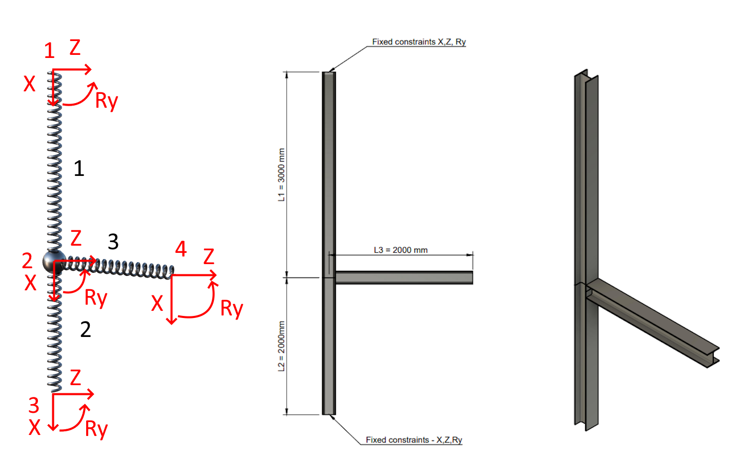
01) Spring model-GCS, geometry, axonometry + sections HEA 200
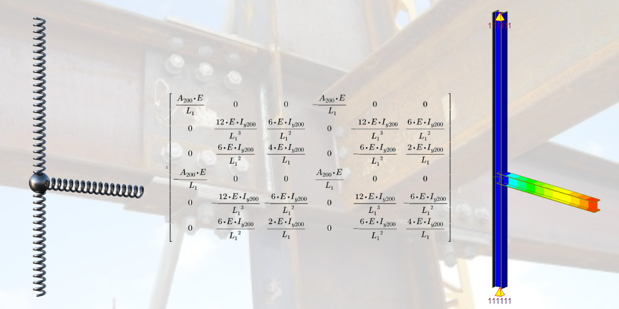
Local stiffness matrix
The stiffness matrix governs the relation between the change of displacements (and rotations) at the beam ends and corresponding forces (reactions). It's worth noting that each node in the 2D workspace has three degrees of freedom (two translations and one rotation), resulting in a local matrix with dimensions of 6x6. This matrix represents the normal stiffness, shear stiffness, and bending stiffness of the element.
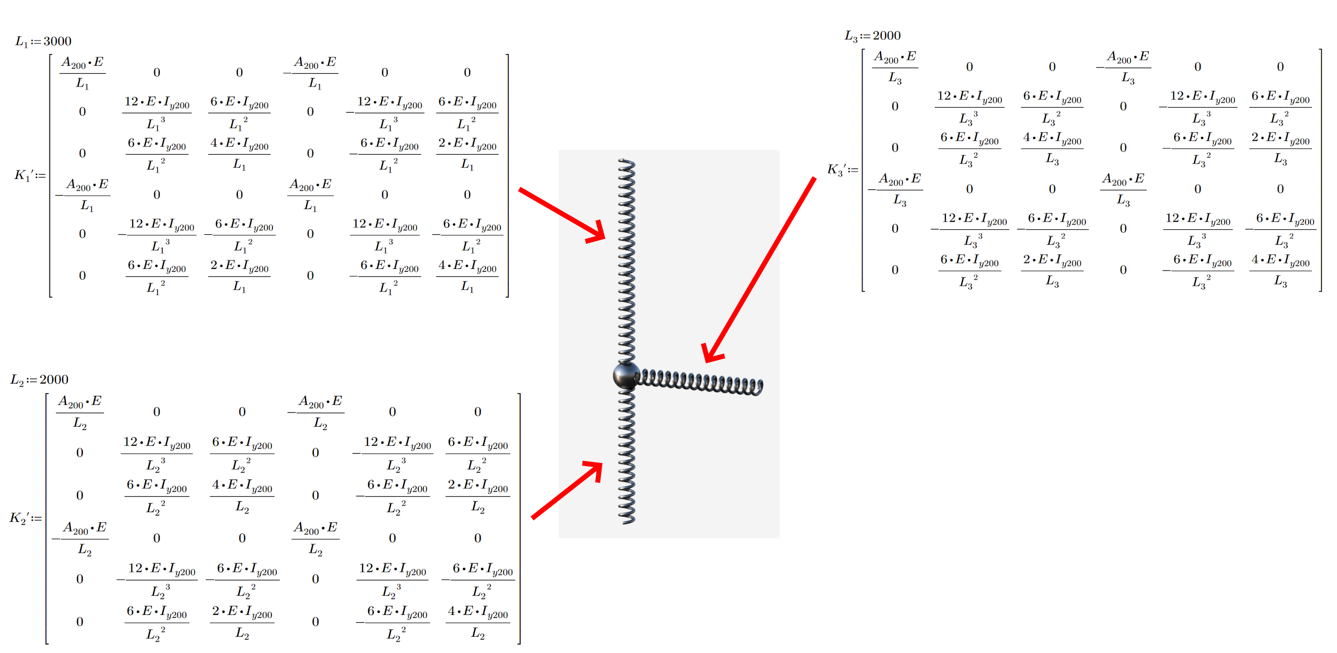
02) Local stiffness matrix of all members
Transformation matrix
In 90% of structures, the local stiffness matrix of members does not align with the global coordinate system. Only simple beams aligned in a straight line have the same Local Coordinate System (LCS) and Global Coordinate System (GCS). In our case, the third element is rotated by 90 degrees around node two. This transformation is necessary for the upcoming calculations.
03) Transformation matrix member 1,2; Transformation matrix member 3
Transformation to a global coordinate system
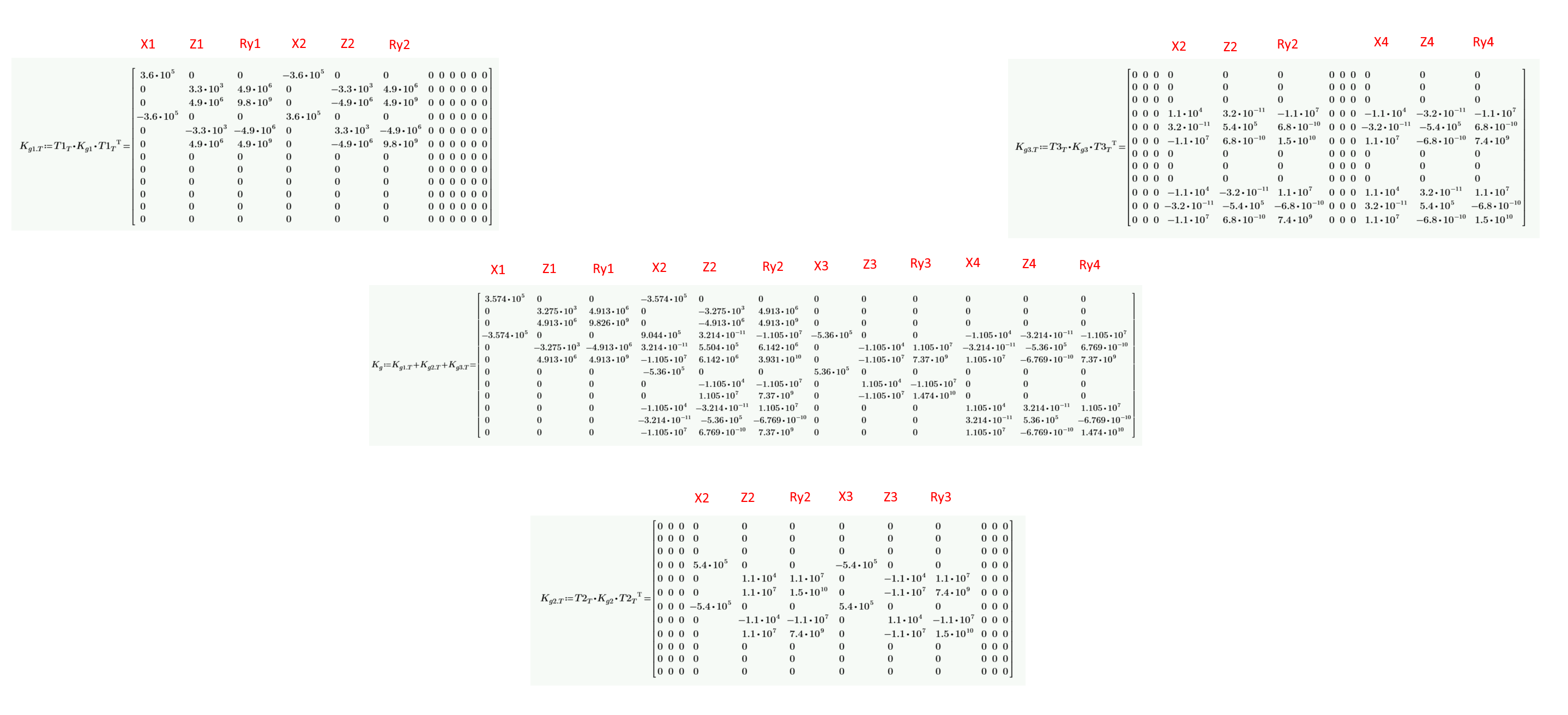
For accurate displacement calculation, it is essential to align the coordinate systems of all the members involved. One way to achieve this is by using a transformation matrix, which simplifies the process and allows for a smooth transition to a displacement calculation. The transformation does not modify the matrix for members one and two as their local coordinate system is the same as the global one. However, you can observe a change in member three, which is rotated by about 90 degrees. The entries for X and Z translations are. You may notice the small nonzero numbers in the matrix. These come from the numerical process, but since they are relatively small with respect to overall stiffness, they do not affect the results in any significant way.
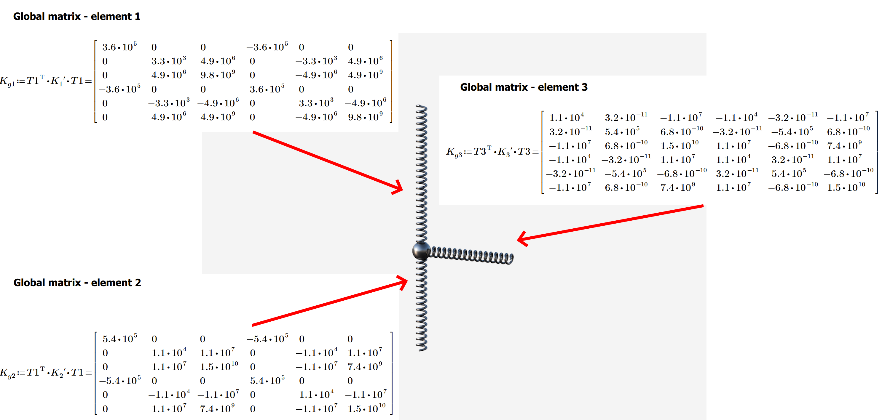
04) Global matrix member 1,2; Global matrix member 3
Global matrix - summation
You have four nodes, and each node has three degrees of freedom. This means the resulting matrix has dimensions of 12x12. The crucial part of the process is adding up the values in columns and rows from individual matrices into the global one.
05) Global stiffness matrix of all system
Boundary condition and load vector
Without boundary conditions, the system is underdetermined (and only the trivial solution can be obtained. In this scenario, fixed constraints are considered at nodes one and three. The zero boundary displacements (and rotations) can be represented by removing the corresponding rows and columns. The solution is trivial if no forces are applied (zero displacements). In our example, node four is subjected to a vertical force of 50 kN.
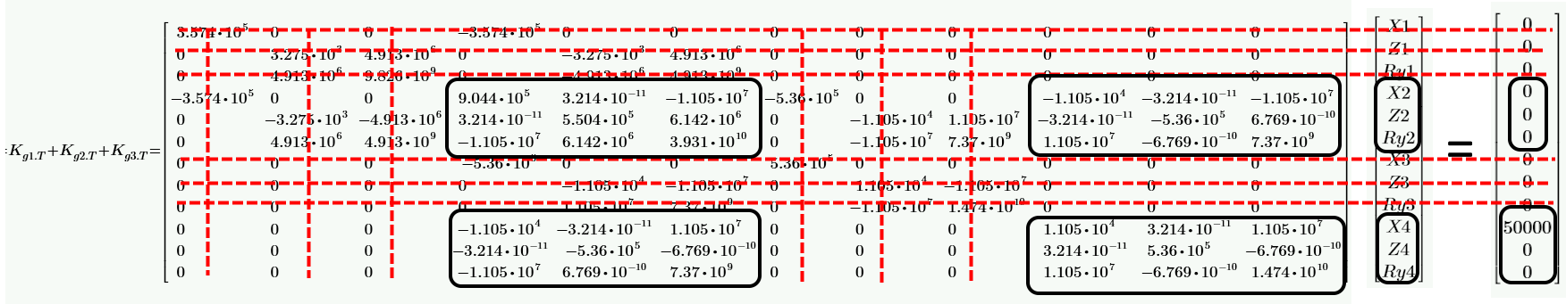
06) Reduced matrix, load vector, and applied boundary conditions
Solution
By taking into account small deformations and linearly elastic material, we can effortlessly solve the vector of unknown displacements in a single step. This approach is swift and highly effective, making it a convenient method for addressing displacement-related concerns.
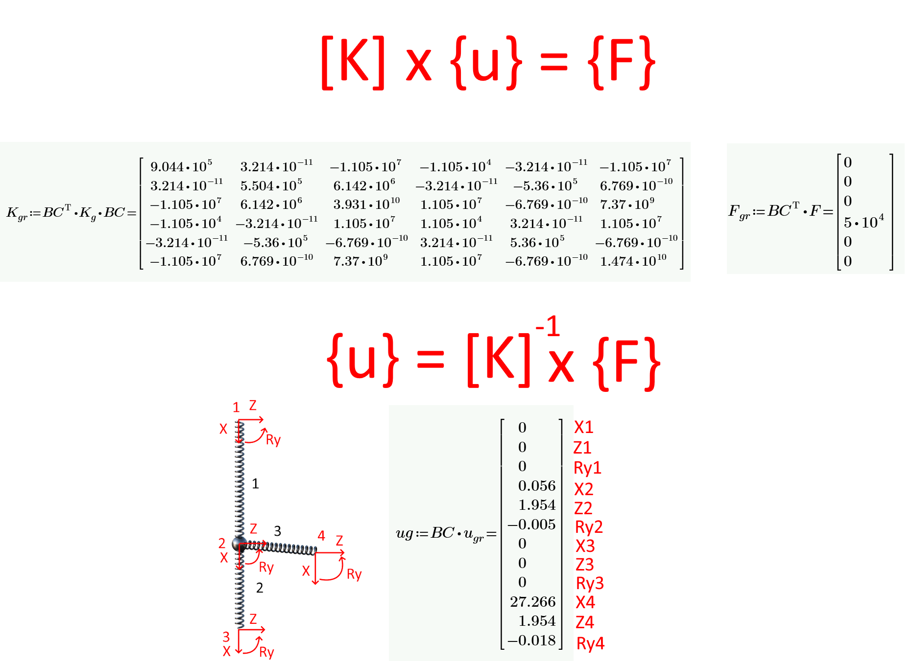
07) Nodal displacement in GCS
FEA verification
Given that the provided values for the nodes are precise, it is imperative that the finite element analysis (FEA) output corresponds exactly with that of the direct stiffness approach (DSA). This requirement ensures that the analytical results are consistent with the actual behavior of the system being studied. Therefore, it is crucial to ensure that the FEA and DSA outputs match each other within the acceptable level of tolerance.
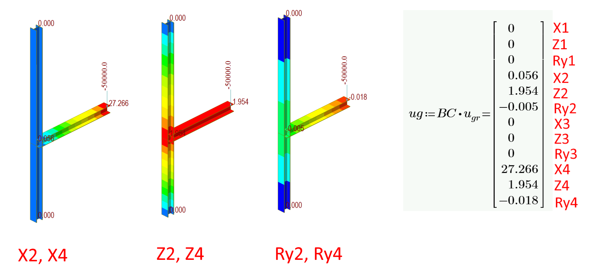
08) Verification and comparison of the nodal displacement between DSA and FEA
Direct stiffness approach – semirigid connections
Understanding that connections are typically semi-rigid and not entirely rigid or pin-like is crucial. Neglecting the stiffness of a connection could result in the behavior of a structure in a model being dissimilar from that of a real structure. Let's delve into how stiffness is taken into account during calculations and how it impacts the behavior of the structure itself.
Rotational spring and civil structures
Civil steel structures, such as halls and frames, are designed to withstand bending loads efficiently transferred by the beams. When the beam is loaded and the structure is hyperstatic, the joint's rotational stiffness plays a crucial role in ensuring correct load redistribution and precise deformation. This is why it is important to maintain the joint's structural integrity to prevent any potential damage to the structure.
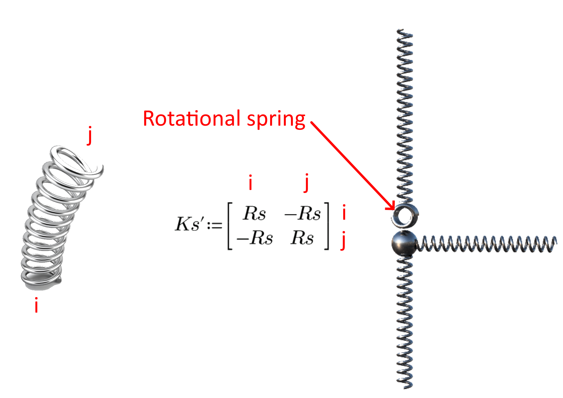
09) Rotational spring - local matrix
To ensure compatibility in a joint, it's important to couple the deformations. This coupling should be included in the global stiffness matrix to calculate the deformations. When rotational stiffness is applied, other degrees of freedom must be included as another row and column in the global stiffness matrix. The final matrix for this type of joint will have a dimension of 13x13, whereas a rigid connection matrix will have a dimension of 12x12.
Impact of rotational stiffness
The rotational stiffness of a structure has a significant impact on how forces are distributed and deformations occur. This means that a structure with rotational stiffness will behave differently than a structure with rigid or pin connections. If the stiffness is increased disproportionately, it can lead to further changes in the behavior of the structure. In this scenario, we will explore the effects of increased rotational stiffness. The model we're working with is from the previous chapter, and the rotational spring is attached to the end (j) of member one.
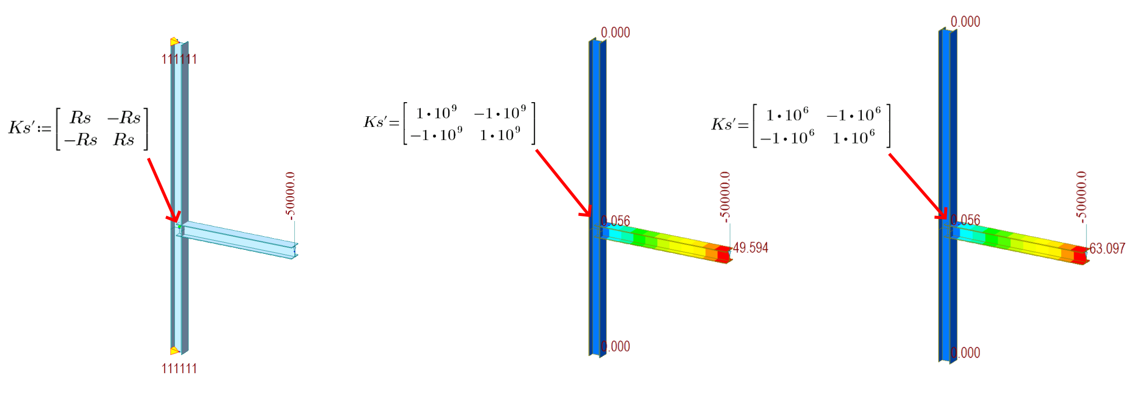
10) Deformations for different rotational stiffness
The graph indicates that, in certain stiffness ranges, the deformation changes in a multilinear manner for a semi-rigid connection. For semi-rigid connections, underestimating or overestimating the stiffness leads to significant differentiation in deflections and redistribution of internal forces.
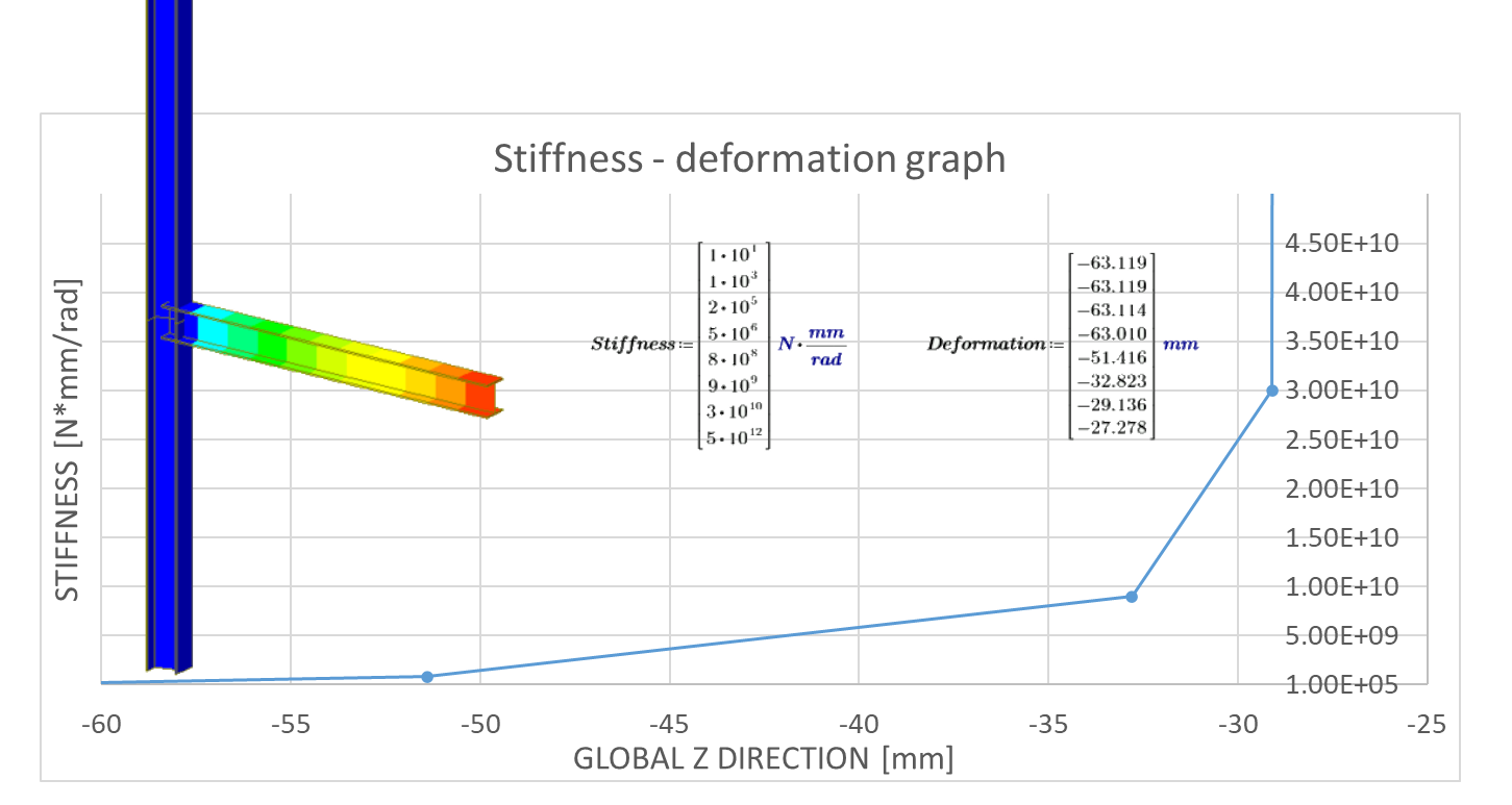
11) Stiffness – deformation graph
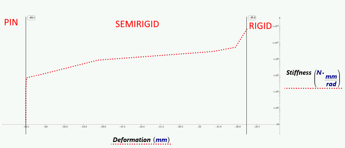
12) Stiffness zone for connections
Conclusion and upcoming topics
To ensure the success of our upcoming study, you must first gain a deep understanding of the problem at hand. Only then can you move forward with confidence and purpose. Our study is devoted to exploring a range of important topics that are relevant to the issue we're investigating. Through careful research and analysis, we hope to shed new light on this complex and challenging problem, and ultimately contribute to a better understanding of this important area of study.
- How is rotational stiffness calculated in IDEA StatiCa
- How to use stiffness for multiple members in an FEA tool
- Verification of the rotational stiffness between IDEA StatiCa and ABAQUS for a plate-to-plate connection
Try IDEA StatiCa for free