Îmbunătățiri ale modelului de analiză în IDEA StatiCa versiunea 21.0
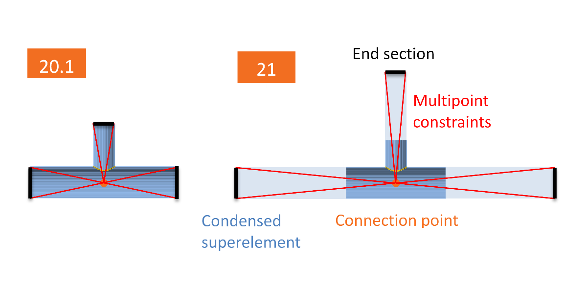
Modelul îmbinării este îmbunătățit semnificativ prin inserarea elementului condensat. Acest element este adăugat în spatele capătului elementului și are aceleași proprietăți ca modelul elastic de tip coajă al elementului. Este un singur element, dar permite oricărei deformații elastice și tensiuni să se dezvolte la capetele elementelor. Datorită acestui fapt, porțiunea elementului alcătuită din elemente de tip coajă poate fi mai scurtă și totuși să îmbunătățească comportamentul modelului. Lungimea implicită atât pentru secțiunile deschise, cât și pentru cele tubulare modelate prin elemente de tip coajă este redusă la 1,25 × cea mai mare dimensiune exterioară a secțiunii transversale. Lungimea elementului condensat este de 4 × cea mai mare dimensiune exterioară a secțiunii transversale (supraelementul nu este vizibil pentru utilizatorul final). Singura diferență apare pentru analizele liniare de flambaj și de rigiditate, unde lungimea elementului condensat este de 0,5 × cea mai mare dimensiune exterioară a secțiunii transversale. Motivul este menținerea formelor proprii de flambaj în plăcile interioare ale îmbinării, și nu în elemente.
Principalele beneficii ale acestei modificări sunt:
- Timpi de calcul cu 30 % mai rapizi (în medie, pe un număr mare de proiecte)
- Vizualizare mai rapidă a rezultatelor
- Modelare mai precisă a îmbinărilor elementelor cu secțiuni tubulare
Această modificare a fost realizată inițial pentru a îmbunătăți analiza îmbinărilor elementelor cu secțiuni tubulare, dar beneficiile se aplică tuturor modelelor.
Care sunt principalele consecințe? Unele rezultate se modifică între versiuni; cu toate acestea, IDEA StatiCa rulează un număr mare de teste automate. În marea majoritate a cazurilor, diferența de rezultate a fost sub 1 %. Totuși, în unele cazuri, diferențele sunt mai mari. Aceste cazuri sunt:
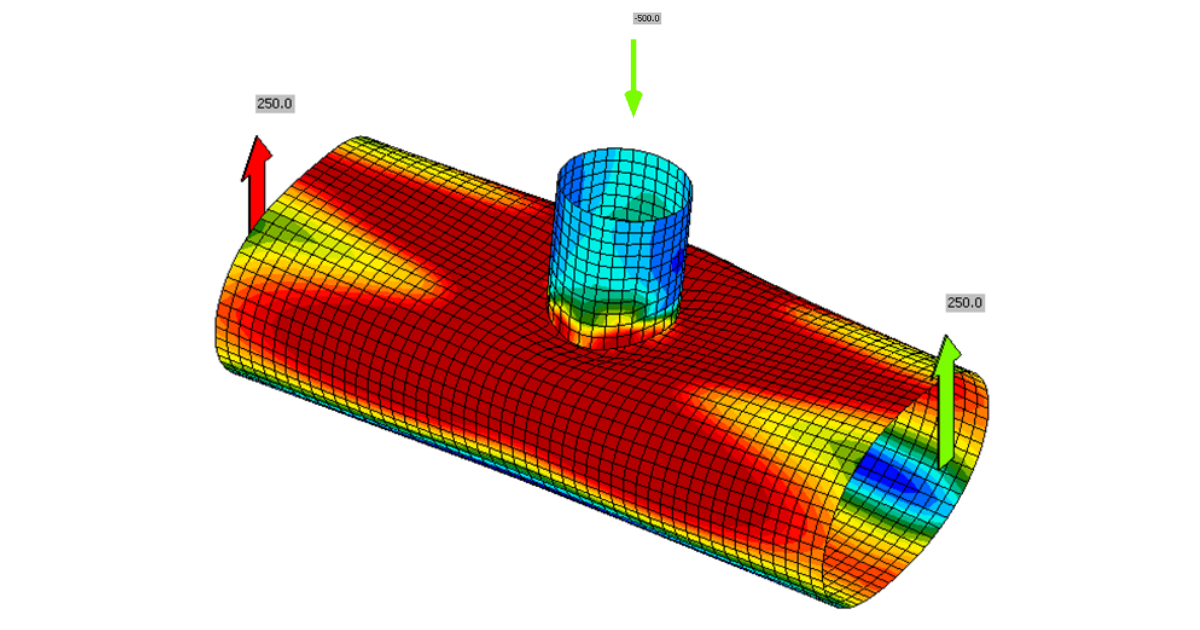
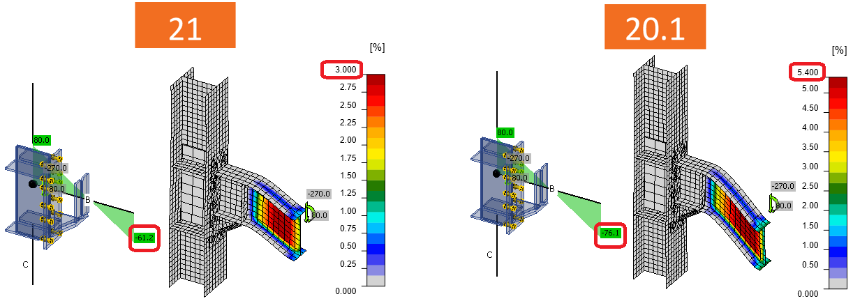
Secțiunea transversală se deformează la capătul modelului de tip coajă
Acest efect a fost principalul motiv pentru care s-a efectuat modificarea. Secțiunea transversală se poate deforma acum la capetele modelului alcătuit din elemente de tip coajă. Nodurile elementelor cu secțiuni tubulare necesită elemente relativ lungi – până la de 10 ori diametrul secțiunii transversale. În caz contrar, condițiile la limită pot afecta rezistența la încărcare a nodului. Prin introducerea elementului condensat în spatele porțiunii modelului alcătuite din elemente de tip coajă, calculul este mult mai rapid cu aceeași precizie.
Rețineți că elementul condensat are doar proprietăți elastice. Deformațiile plastice nu ar trebui să atingă capetele elementelor. În caz contrar, acestea pot afecta rezistența îmbinării.
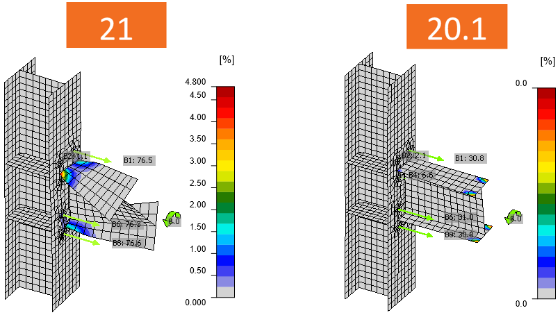
Tronsonele scurte mai scurte ale elementelor nu curg la capete
Aceasta este o problemă care apare, de exemplu, la consolele de coloană încărcate puternic la forfecare de o forță foarte apropiată de îmbinare. Prin utilizarea unor elemente mai scurte, momentul încovoietor la capătul elementului este redus.
Dacă tronsonul scurt al elementului cedează totuși la încovoiere, soluția alternativă este modelarea elementului prin elementul de rigidizare și utilizarea unui element fictiv pentru aplicarea forței tăietoare.
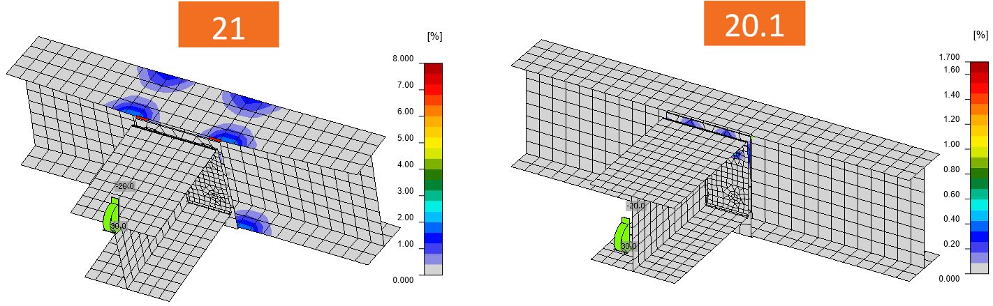
Torsiune
Deplanarea era reținută de constrângerile multipunct care conectau nodul cu capătul grinzii. Aceste constrângeri sunt utilizate pentru a impune încărcările în model. Acum, elementul condensat împinge constrângerile mai departe, iar elementul poate să se deformeze. Aceasta conduce la un bimoment (moment de deplanare) mai mare în îmbinare.
Acesta este adesea cazul unui nod unilateral al grinzii secundare față de grinda principală. Rețineți că proiectarea elementului trebuie efectuată separat și că bimomentul cauzat de deplanare este foarte adesea neglijat de pachetele software, dar trebuie luat în considerare. Rezistența la deplanare a elementelor cu secțiuni deschise este surprinzător de mică.
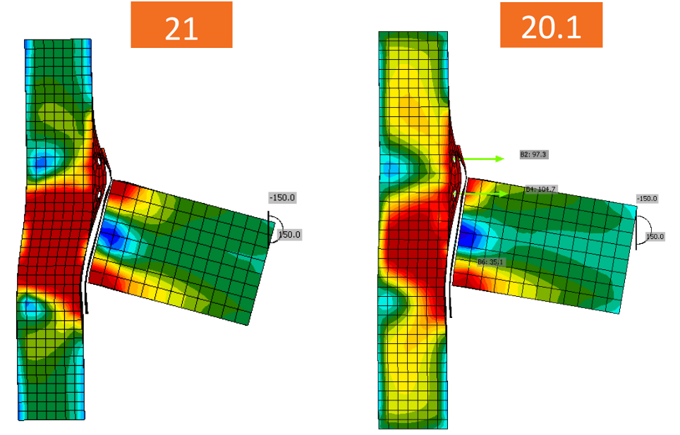
Încărcare simplificată / Încărcări în echilibru
Când se utilizează încărcarea simplificată și elementul continuu este selectat ca element portant, forțele interioare sunt diferite deoarece lungimile elementelor s-au modificat de la 1,5 × h la (1,25 + 4) × h.
- Forțele interioare sunt diferite
- Inima coloanei în zona panoului solicitat la forfecare este încărcată mai puternic. Cu toate acestea, opțiunea încărcări în echilibru este necesară pentru a surprinde corect comportamentul elementului continuu.
Utilizarea opțiunii Încărcări în echilibru este întotdeauna recomandată.
Rezistența la încovoiere a elementelor de tip coajă redusă pentru secțiunile tubulare
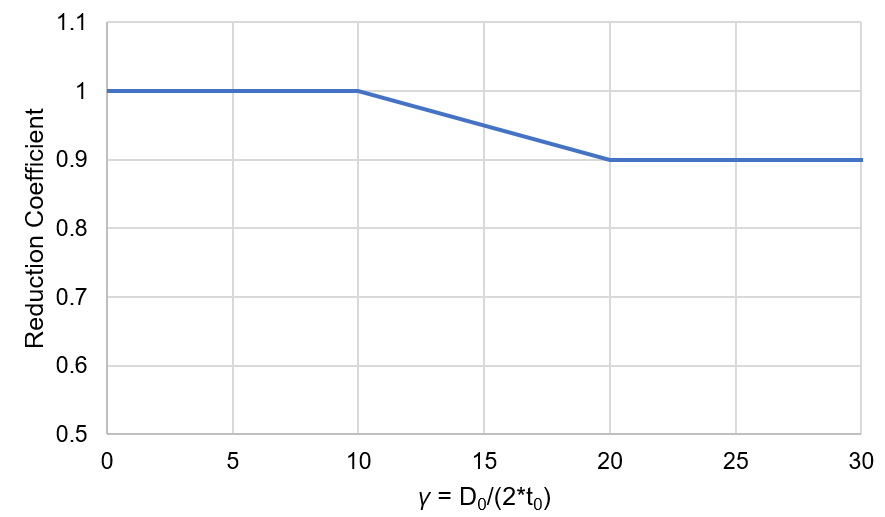
Rezistențele la încărcare ale nodurilor cu secțiuni tubulare din coduri sunt determinate prin Metoda Modurilor de Cedare, care utilizează modele de ajustare a curbelor determinate din experimente și modele numerice avansate. Această metodă de proiectare este implementată în toate codurile. În prezent, cel mai recent stadiu al tehnicii se regăsește într-un proiect de prEN 1993-1-8:2022. Structura reală conține imperfecțiuni inițiale și tensiuni reziduale, care nu sunt surprinse de modelele de tip coajă din IDEA StatiCa Connection. Pentru a obține o conformitate mai bună cu rezultatele codurilor, influența tensiunilor reziduale și a imperfecțiunilor inițiale a fost introdusă în modelele IDEA StatiCa prin reducerea rezistenței la încovoiere a elementelor de tip coajă ale secțiunilor tubulare cu un raport D/(2t) ridicat. Aceasta permite reducerea rezistenței modurilor de cedare ale nodurilor, menținând în același timp rezistența normală și la încovoiere a elementelor cu secțiuni tubulare. Reducerea rezistenței plastice a elementelor de tip coajă depinde de factorul \(\gamma = \frac{D_0}{2t_0}\):
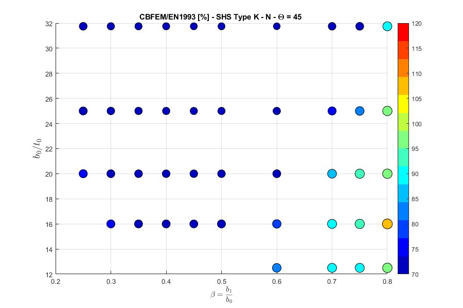
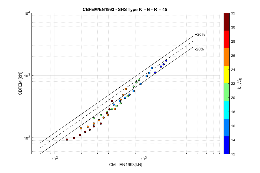
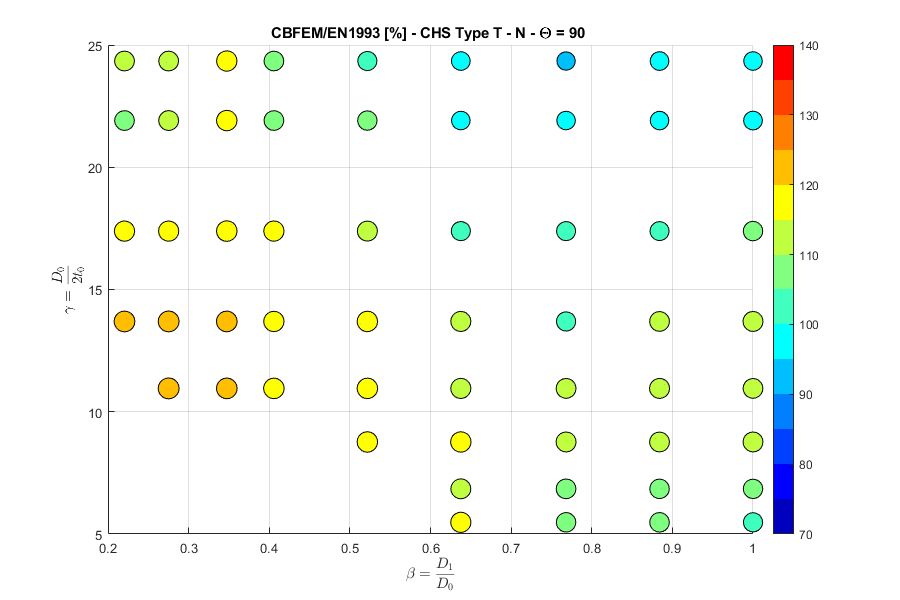
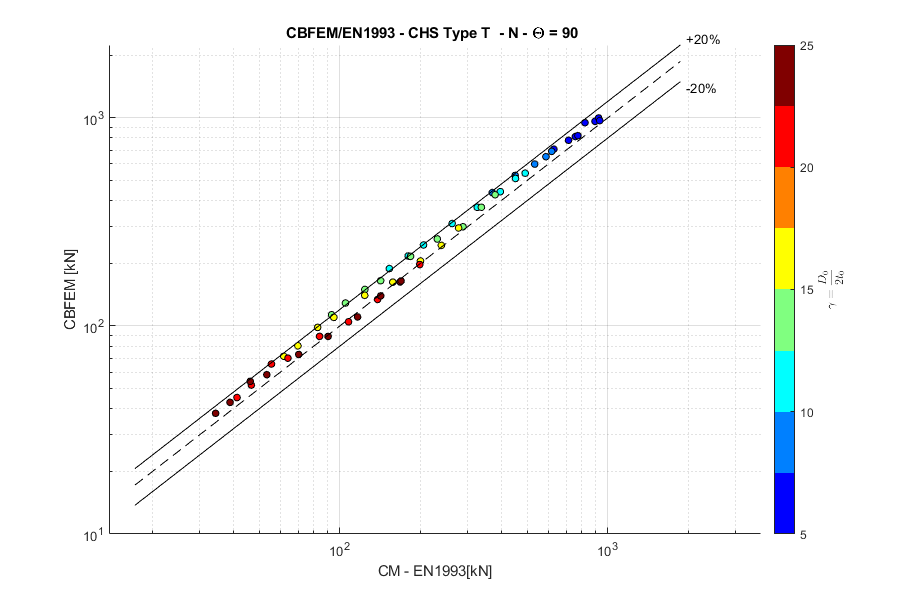
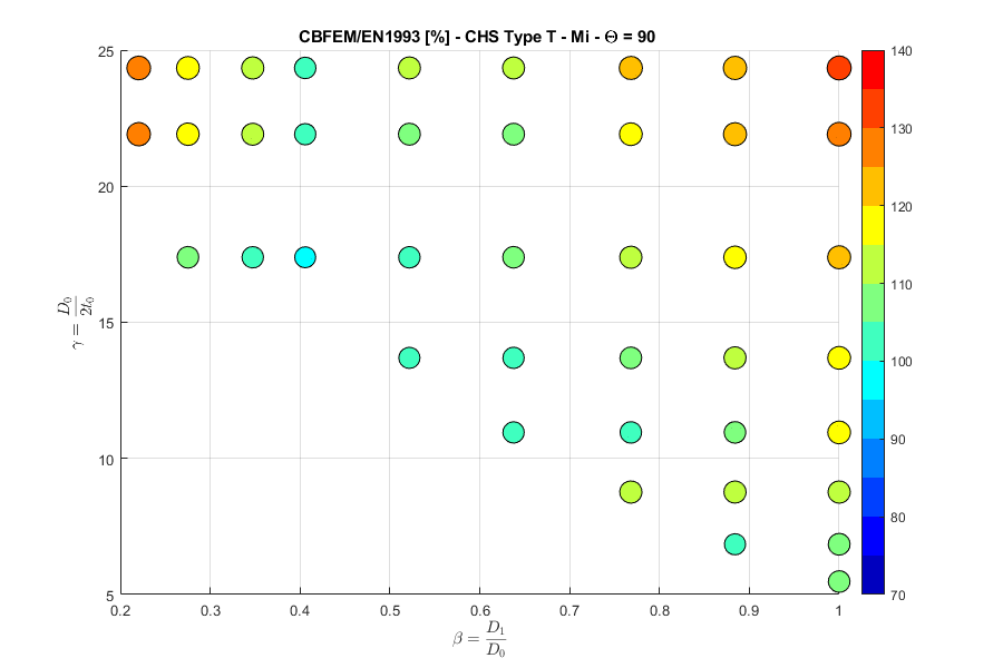
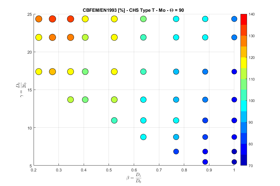
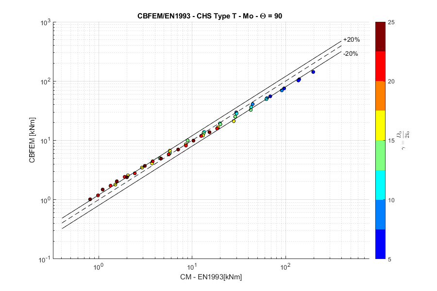
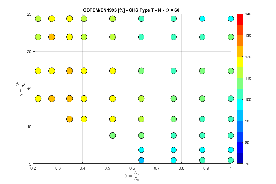
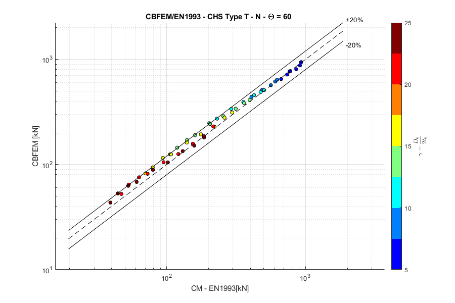
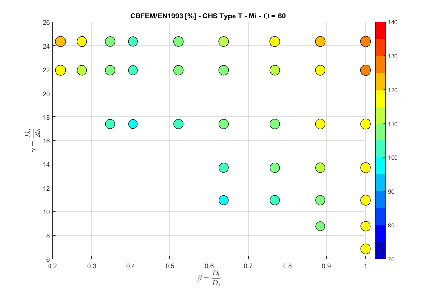
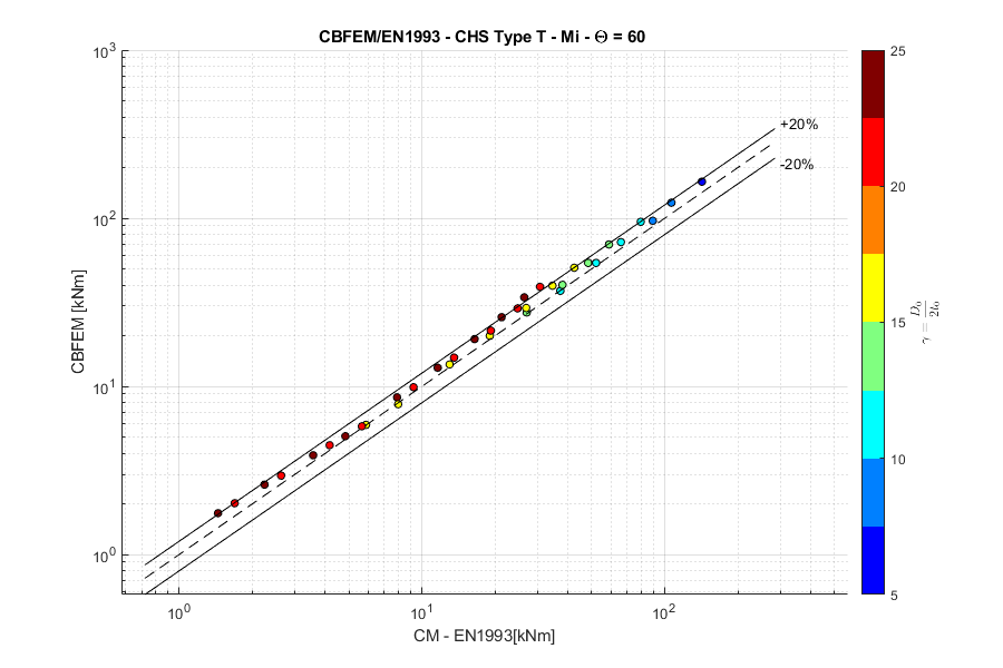
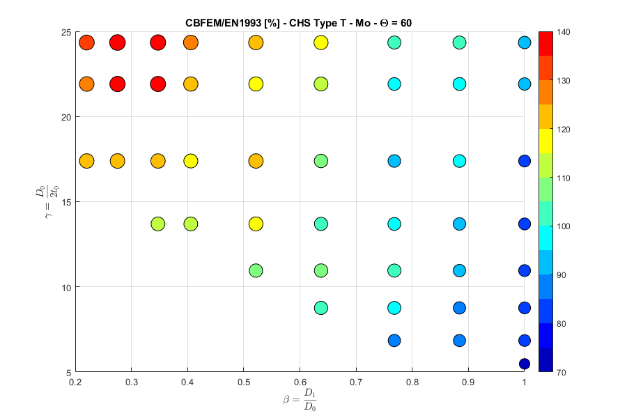
Aceste modificări combinate ne-au permis să obținem o concordanță bună cu rezultatele Metodei Modurilor de Cedare (FMM) din codurile de proiectare. Conformitatea dintre IDEA StatiCa Connection și FMM este prezentată în figurile următoare.
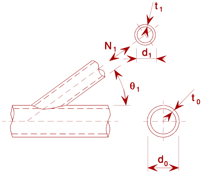
Secțiuni circulare tubulare
Nod T, forță normală, unghi \(\theta = 90 ^\circ\)
Nod T, moment încovoietor în plan, unghi \(\theta = 90 ^\circ\)

Nod T, moment încovoietor în afara planului, unghi \(\theta = 90 ^\circ\)
Nod Y, forță normală, unghi \(\theta = 60 ^\circ\)
Nod Y, moment încovoietor în plan, unghi \(\theta = 60 ^\circ\)
Nod Y, moment încovoietor în afara planului, unghi \(\theta = 60 ^\circ\)

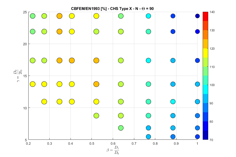
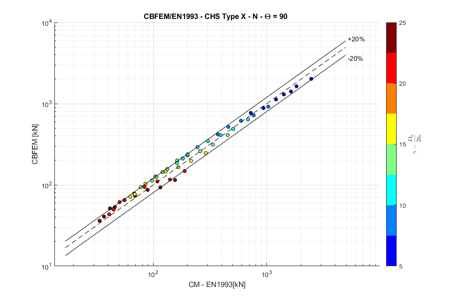
Nod X, forță normală, unghi \(\theta = 90 ^\circ\)
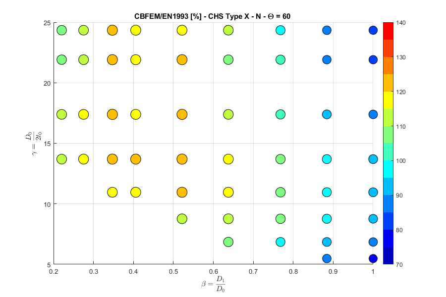
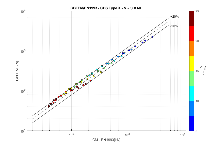
Nod X, forță normală, unghi \(\theta = 60 ^\circ\)
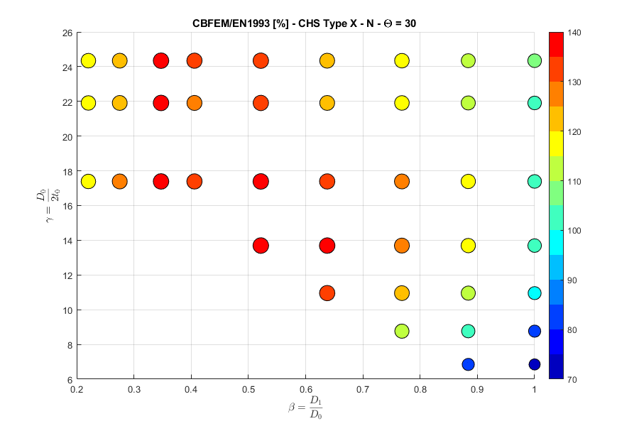
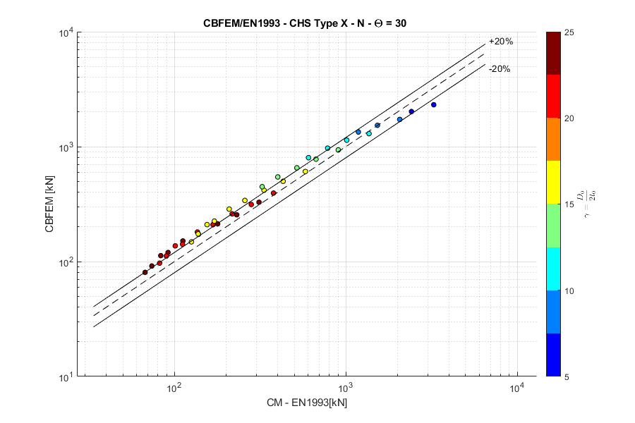
Nod X, forță normală, unghi \(\theta = 30 ^\circ\)
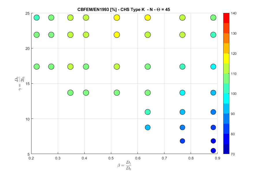
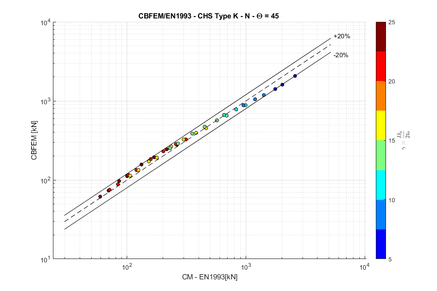
Nod K, forță normală, unghi \(\theta = 45 ^\circ\)
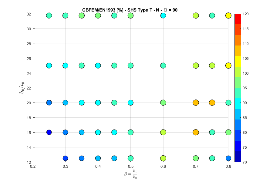
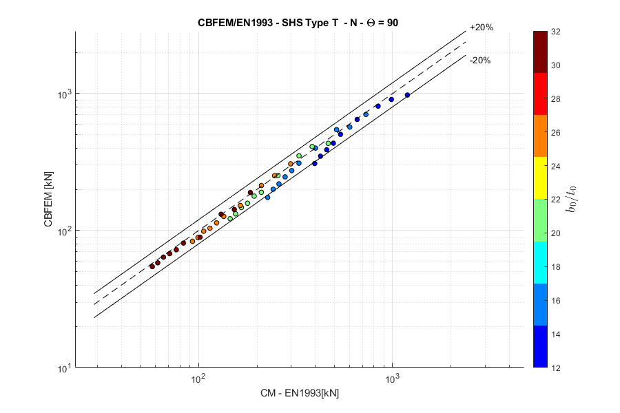
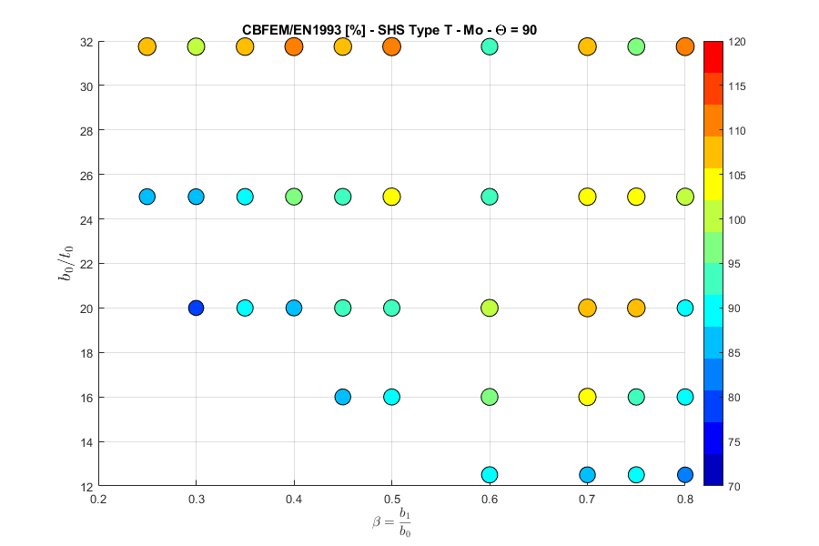
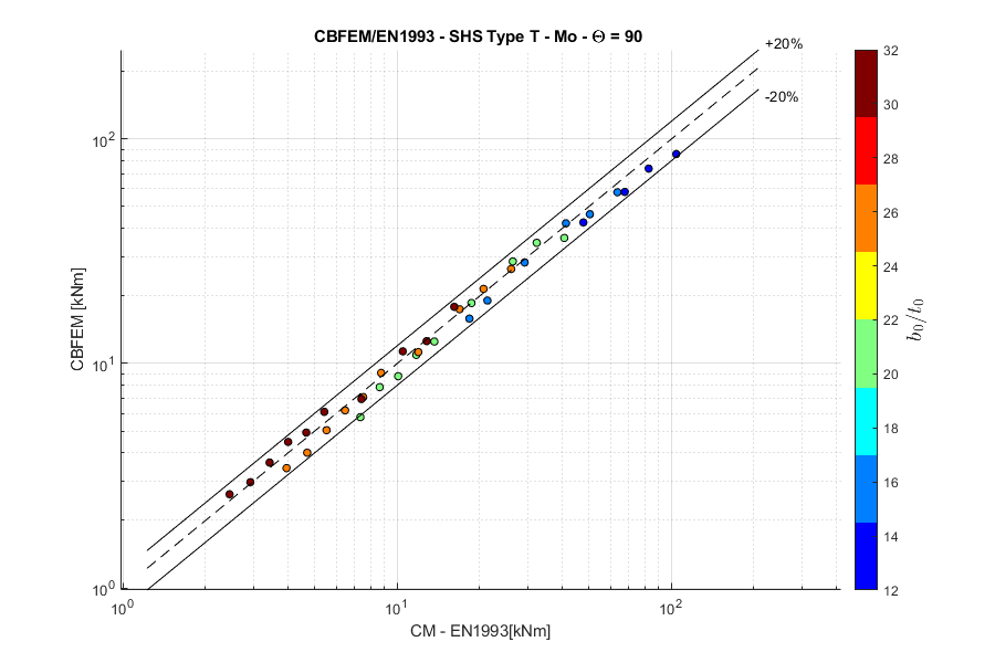
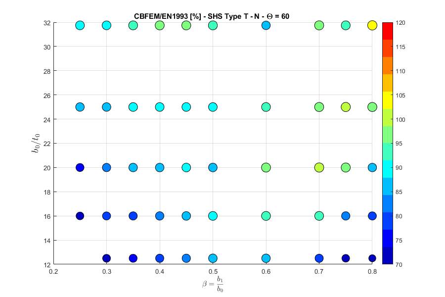
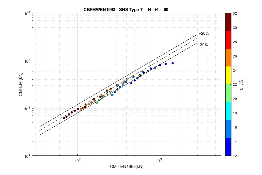
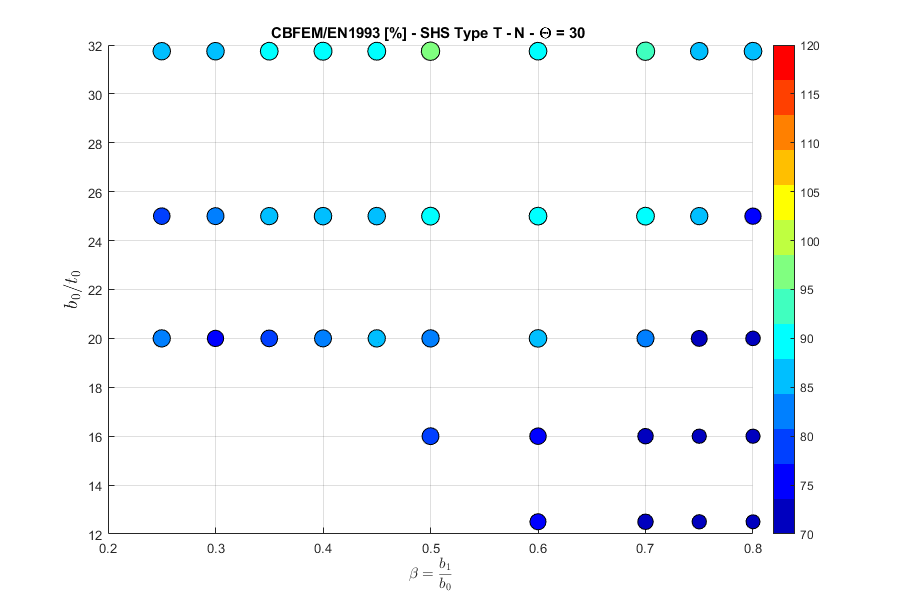
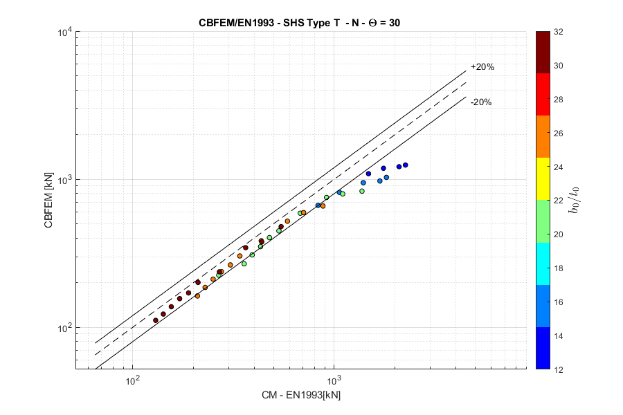
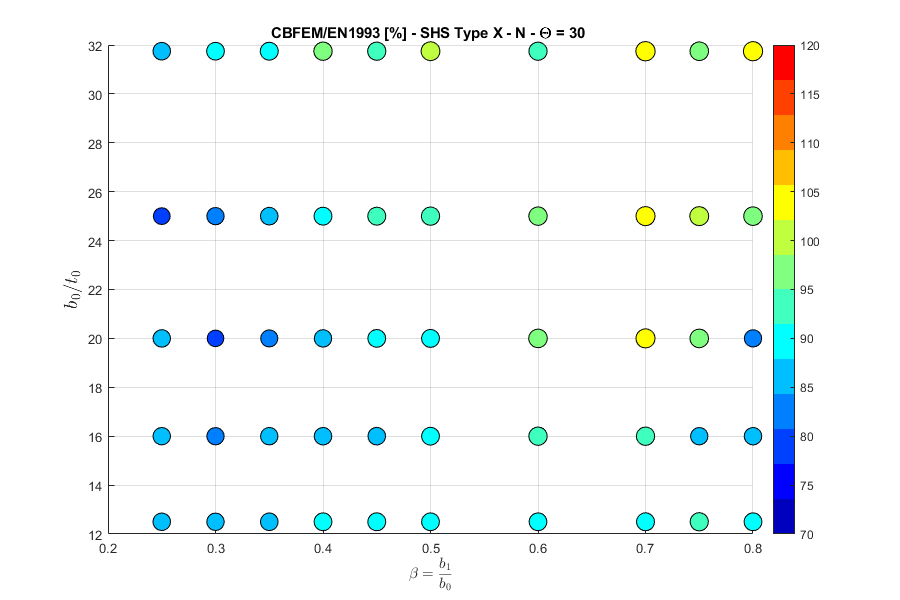
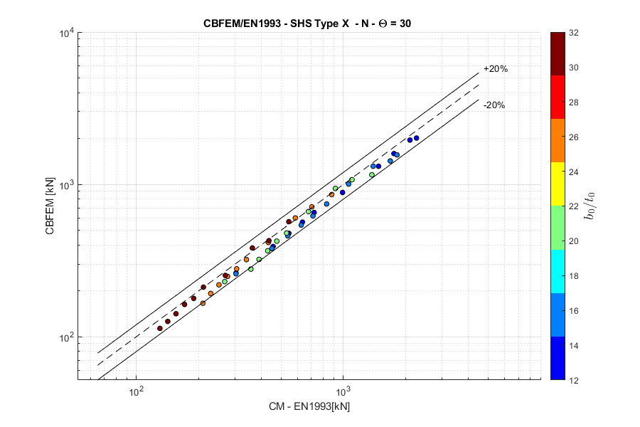
Secțiuni pătrate tubulare
Nod T, forță normală, unghi \(\theta = 90 ^\circ\)
Rețineți că reducerea rezistenței datorată încărcării în talpă nu este luată în considerare în modelul FMM. Aceasta explică diferența de rezultate.
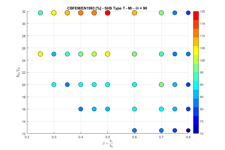
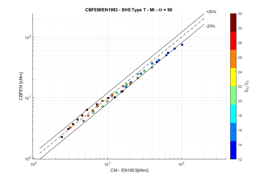
Nod T, moment încovoietor în plan, unghi \(\theta = 90 ^\circ\)
Nod T, moment încovoietor în afara planului, unghi \(\theta = 90 ^\circ\)
Nod Y, forță normală, unghi \(\theta = 60 ^\circ\)
Rețineți că reducerea rezistenței datorată încărcării în talpă nu este luată în considerare în modelul FMM. Aceasta explică diferența de rezultate.
Nod Y, forță normală, unghi \(\theta = 30 ^\circ\)
Rețineți că reducerea rezistenței datorată încărcării în talpă nu este luată în considerare în modelul FMM. Aceasta explică diferența de rezultate.
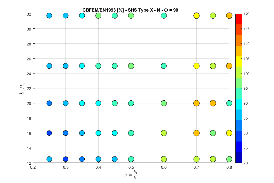
Nod X, forță normală, unghi \(\theta = 90 ^\circ\)

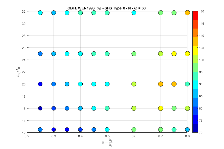
Nod X, forță normală, unghi \(\theta = 60 ^\circ\)

Nod X, forță normală, unghi \(\theta = 30 ^\circ\)
Nod K, forță normală, unghi \(\theta = 45 ^\circ\)