Verificarea componentelor îmbinării metalice (GB)
Metoda CBFEM combină avantajele Metodei Elementelor Finite (MEF) generale și ale Metodei Componentelor (MC) standard. Tensiunile și forțele interioare calculate pe modelul CBFEM precis sunt utilizate în verificarea tuturor componentelor – Șuruburile, șuruburile pretensionate și sudurile sunt verificate conform GB 50017 – 2017. Plăcile sunt verificate prin analiza cu elemente finite. Verificările ancorajului nu au fost încă implementate în versiunea curentă.
Verificarea conform codului a plăcilor din oțel conform Standardului Chinez
Tensiunea echivalentă rezultantă (HMH, von Mises) și deformația principală plastică sunt calculate pe plăci. Când rezistența de curgere de calcul, f (GB 50017, Tabelul 4.4.1–4.4.3), pe diagrama bilineară a materialului este atinsă, se efectuează verificarea deformației plastice echivalente. Valoarea limită de 5 % este recomandată în Eurocode (EN 1993-1-5 App. C, Par. C8, Nota 1). Această valoare poate fi modificată în configurarea codului, dar studiile de verificare au fost efectuate pentru această valoare recomandată.
Elementul de placă este împărțit în cinci straturi, iar comportamentul elastic/plastic este investigat în fiecare dintre acestea. Programul afișează cel mai defavorabil rezultat dintre toate.
Tensiunea poate fi ușor mai mare decât rezistența de curgere de calcul. Motivul este panta ușoară a ramului plastic al diagramei efort-deformație, care este utilizată în analiză pentru a îmbunătăți stabilitatea calculului.
Verificarea conform codului a șuruburilor și șuruburilor pretensionate conform standardului chinez
Șuruburi
Șuruburile sunt verificate conform GB 50017, Cl. 11.4. Forța de întindere și forța de forfecare din fiecare șurub sunt determinate prin analiza cu elemente finite. Efectul de pârghie este determinat prin analiza cu elemente finite și luat în considerare. Fiecare plan de forfecare este verificat individual. Placa în contact direct este verificată față de suma forțelor de forfecare din planele adiacente.
Rezistențele de calcul la întindere și forfecare ale unui șurub; fub[MPa] – rezistența ultimă a unui șurub; derivată din Tabelul 4.4.6
| \(f_{ub}\) [MPa] | \(f_t^b \) | \(f_v^b\) |
| \(f_{ub} \le 400 \) | \(0.425 \cdot f_{ub}\) | \(0.35 \cdot f_{ub}\) |
| \(400<f_{ub}<830\) | \(0.42 \cdot f_{ub}\) | \(0.38 \cdot f_{ub}\) |
| \(830 \le f_{ub}\) | \(40/83 \cdot f_{ub}\) | \(32/83 \cdot f_{ub}\) |
Șurub solicitat la întindere
Un șurub supus unei forțe de întindere este dimensionat conform Cl. 11.4.1.2 și trebuie să satisfacă:
\[ N_t \le N_t^b = A_s \cdot f_t^b \]
unde:
- Nt – forța de întindere dintr-un șurub
- Ntb – capacitatea de calcul la întindere
- \( A_s = \frac{\pi d_e^2}{4} \) – aria secțiunii transversale efective la întindere a unui șurub
- de – diametrul efectiv al unui șurub la secțiunea filetată
- ftb – rezistența de calcul la întindere a unui șurub
Șuruburi solicitate la forfecare
Un șurub supus unei forțe de forfecare este dimensionat conform Cl. 11.4.1.1 și trebuie să satisfacă:
\[ N_v \le N_v^b = A_g \cdot f_v^b \]
unde:
- Nv – forța de forfecare dintr-un șurub în planul analizat
- \( A_g = \frac{\pi d^2}{4} \) – aria brută a secțiunii transversale a unui șurub
- d – diametrul nominal al unui șurub
- fvb – rezistența de calcul la forfecare a unui șurub
Fiecare plan de forfecare este verificat individual, adică numărul planelor de forfecare nv = 1.
Șuruburi solicitate la întindere și forfecare combinate
Un șurub solicitat simultan la forfecare și întindere este dimensionat conform Cl. 11.4.1.3 și trebuie să satisfacă:
\[ \sqrt{\left ( \frac{N_v}{N_v^b} \right ) ^2 + \left ( \frac{N_t}{N_t^b} \right ) ^2} \le 1.0 \]
unde:
- Nv – forța de forfecare dintr-un șurub în planul analizat
- Nt – forța de întindere dintr-un șurub
- Nvb – rezistența de calcul la forfecare a unui șurub
- Ntb – rezistența de calcul la întindere a unui șurub
Șuruburi solicitate la presiune pe gaură
O placă supusă unei forțe de presiune pe gaură datorată unui șurub solicitat la forfecare este dimensionată conform Cl. 11.4.1.1 și trebuie să satisfacă:
\[ N_v \le N_c^b = d\cdot t \cdot f_c^b \]
unde:
- Nv – forța de forfecare care acționează asupra unei plăci; suma vectorială a forțelor de forfecare din planele adiacente
- d – diametrul nominal al șurubului
- t – grosimea plăcii
- fcb – rezistența de calcul la presiune pe gaură a unei plăci

Rezistența de calcul la presiune pe gaură a unei plăci; fu – rezistența ultimă a unei plăci; derivată din Tabelul 4.4.6
Șuruburi pretensionate
Șurubul de înaltă rezistență în îmbinare de tip frecare este dimensionat conform Cl. 11.4.2.
Șuruburi pretensionate solicitate la întindere
Rezistența la întindere a unui șurub pretensionat se determină astfel:
\[ N_t \le N_t^b = 0.8 \cdot P \]
unde:
- Nt – forța de întindere dintr-un șurub
- Ntb – capacitatea de calcul la întindere
- P – pretensionarea unui șurub de înaltă rezistență – Tabelul 11.4.2-2
Tabelul 11.4.2-2 – pretensionarea unui șurub de înaltă rezistență P [kN]
| Clasa șurubului | M16 | M20 | M22 | M24 | M27 | M30 |
| 8.8 | 80 | 125 | 150 | 175 | 230 | 280 |
| 10.9 | 100 | 155 | 190 | 225 | 290 | 355 |
Un șurub pretensionat care nu se regăsește în Tabelul 11.4.2-2 și este supus unei forțe de întindere este dimensionat conform Cl. 11.4.1.2 și trebuie să satisfacă:
\[ N_t \le N_t^b = A_s \cdot f_t^b \]
unde:
- Nt – forța de întindere dintr-un șurub
- Ntb – capacitatea de calcul la întindere
- \( A_s = \frac{\pi d_e^2}{4} \) – aria secțiunii transversale efective la întindere a unui șurub
- de – diametrul efectiv al unui șurub la secțiunea filetată
- ftb – rezistența de calcul la întindere a unui șurub
Șuruburi pretensionate solicitate la forfecare
Rezistența de calcul la forfecare a unui șurub pretensionat se determină conform Cl. 11.4.2.1:
\[ N_v \le N_v^b = 0.9 k \mu P \]
unde:
- Nv – forța de forfecare în planul analizat
- Nvb – rezistența de calcul la forfecare a unui șurub
- k – factor pentru găurile șuruburilor; k = 1 pentru găuri normale, k = 0.85 pentru găuri supradimensionate, k = 0.6 pentru găuri alungite
- μ – coeficientul de alunecare la interfața de frecare, preluat din Tabelul 11.4.2-1; editabil în Configurarea codului
- P = Ntb / 0.8 – pretensionarea unui șurub de înaltă rezistență pentru șuruburile care nu se regăsesc în Tabelul 11.4.2-2
Fiecare plan de forfecare este verificat individual, adică numărul planelor de forfecare nf = 1.
Șuruburi pretensionate solicitate la întindere și forfecare combinate
Un șurub solicitat simultan la forfecare și întindere este dimensionat conform Cl. 11.4.2.3 și trebuie să satisfacă:
\[ \frac{N_v}{N_v^b} + \frac{N_t}{N_t^b} \le 1.0 \]
unde:
- Nv – forța de forfecare în planul analizat
- Nt – forța de întindere dintr-un șurub
- Nvb – rezistența de calcul la forfecare a unui șurub
- Ntb – rezistența de calcul la întindere a unui șurub
Verificarea conform codului a sudurilor conform standardului chinez
Sudurile de colț sunt verificate conform GB 50017 - Capitolul 11. Rezistența sudurilor cap la cap este considerată egală cu cea a metalului de bază și nu este verificată.
Suduri cap la cap
Se presupun suduri cap la cap cu penetrare completă, iar rezistența lor este considerată egală cu cea a metalului de bază – Cl. 11.2.1.
Suduri de colț
Rezistența de calcul a sudurilor de colț este verificată conform Cl. 11.2.2.2:
\[ \sigma_w = \sqrt{ \left ( \frac{\sigma_f}{\beta_f} \right ) ^2 + \tau_f^2} \le f_f^w \]
unde:
- σf – tensiunea pe aria efectivă a sudurii perpendiculară pe lungimea sudurii
- βf – coeficient de majorare pentru valoarea de calcul a rezistenței sudurii de colț; βf = 1,22 pentru încărcare statică și unghi între fețele de fuziune α = 90°; în caz contrar βf = 1,0
- τf – tensiunea de forfecare pe aria efectivă a sudurii paralelă cu lungimea sudurii
- ffw – rezistența de calcul a sudurii de colț
Rezistența de calcul a sudurii de colț ffw pentru electrozi de sudare; derivată din Tabelul 4.4.5
| Electrod | \(f_f^w\) [MPa] |
| E43 | 160 |
| E50 | 200 |
| E55 | 220 |
| E60 | 240 |
Electrozii impliciți sunt E43 pentru placa conectată cu rezistența cea mai mică, cu fu < 470 MPa, E50 pentru 470 MPa ≤ fu < 520 MPa și E55 pentru 520 MPa ≤ fu.
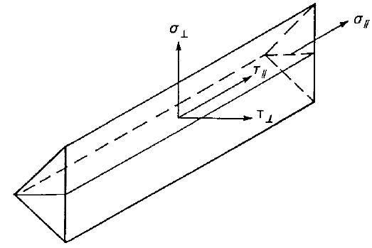
Diagramele de sudură prezintă tensiunea conform formulei următoare:
\[ \sigma = \sqrt{ \frac{1}{\beta_f^2}(\sigma_{\perp}^2 + \tau_{\perp}^2) + \tau_{\parallel}^2 } \]
Detaliere buloane și suduri conform standardului chinez
Buloane
Distanța minimă admisă a buloanelor este verificată conform Tabelului 11.5.2.
Distanța minimă admisă a buloanelor; d0 – diametrul găurii pentru buloane
| Distanța minimă admisă | |
| Pasul buloanelor | \( 3 \cdot d_0 \) |
| Distanța la capăt paralelă cu direcția forței | \( 2 \cdot d_0 \) |
| Distanța la margine perpendiculară pe direcția forței (buloane de tip presiune pe gaură) | \( 1.2 \cdot d_0 \) |
| Distanța la margine perpendiculară pe direcția forței (buloane pretensionate) | \( 1.5 \cdot d_0 \) |
Suduri
Dimensiunea minimă a sudurii hf este verificată conform Tabelului 11.3.5. Dimensiunea sudurii este determinată din grosimea gâtului de sudură: \( h_f = \sqrt{2} \cdot h_e \).
Dimensiunea minimă a sudurii hf
| Grosimea plăcii [mm] | Dimensiunea minimă a sudurii [mm] |
| \( t \le 6 \) | 3 |
| \( 6 < t \le 12 \) | 5 |
| \( 12 < t \le 20 \) | 6 |
| \( 20<t \) | 8 |
Verificarea conform codului a blocului de beton conform standardului chinez
Betonul de sub placa de bază este simulat prin subsolul Winkler cu rigiditate uniformă, care furnizează tensiunile de contact. Tensiunea medie la suprafața de reazem este utilizată pentru verificarea la compresiune.
Beton la reazem
Utilizatorul poate alege între verificarea capacității portante locale a unui bloc de beton armat (GB 50010, Ecuația 6.6.1-1) și a unui bloc de beton simplu (GB 50010, Ecuația D.5.1-1).
Bloc de beton armat
\[ F_l \le F_c = 1.35 \beta_c \beta_l f_c A_{ln} \]
Bloc de beton simplu
\[ F_l \le F_c = \omega \beta_l f_{cc} A_l \]
unde:
- Fl – forță de compresiune
- Fc – rezistență la compresiune
- βc – coeficient de influență a rezistenței betonului; βc = 1 pentru clasa de beton până la C50, βc = 0.8 pentru clasa de beton C80; interpolarea liniară se utilizează pentru clasele de beton între C50 și C80
- \( \beta_l = \sqrt{\frac{A_b}{A_l}} \) – factor de concentrare
- Ab – suprafața de rezemare a betonului concentrică cu Al
- Al – aria plăcii de bază în contact cu suprafața de beton
- Aln – aria Al cu scăderea găurilor din placa de bază pentru ancore
- fc – valoare de calcul a rezistenței la compresiune a betonului; GB50010, Tabelul 4.1.4-1
- fcc = 0.85 fc – valoare de calcul a rezistenței la compresiune a betonului simplu; GB50010, Tabelul 4.1.4-1
- ω – factor de distribuție a încărcării de compresiune; ω = 0.75 pentru distribuție neuniformă a încărcării, ω = 1.0 pentru distribuție uniformă a încărcării
Transferul forței de forfecare
Se presupune că acțiunea de forfecare la placa de bază este transferată de la stâlp la fundația de beton prin:
- Frecare între placa de bază și beton / mortar de nivelare
- Pivot de forfecare
- Buloane de ancorare
Ancore
Forțele de întindere din ancore includ efectul de pârghie și sunt determinate prin analiza cu elemente finite.
Ancorele nu sunt verificate în software.
Clasificarea rosturilor conform standardului chinez
Rosturile sunt clasificate în funcție de rigiditatea rostului în:
- Rigid – rosturi cu modificare nesemnificativă a unghiurilor inițiale dintre elemente,
- Semi-rigid – rosturi care se presupune că au capacitatea de a furniza un grad cunoscut și fiabil de încastrare la încovoiere,
- Articulat – rosturi care nu dezvoltă momente încovoietoare.
Nu există o limită clară între clasele de rosturi în GB 50017 și, prin urmare, rosturile sunt clasificate conform EN 1993-1-8 – Cl. 5.2.2.
- Rigid – \( \frac{S_{j,ini} L_b}{E I_b} \ge k_b \)
- Semi-rigid – \( 0.5 < \frac{S_{j,ini} L_b}{E I_b} < k_b \)
- Articulat – \( \frac{S_{j,ini} L_b}{E I_b} \le 0.5 \)
unde:
- Sj,ini – rigiditatea inițială a rostului; rigiditatea rostului se consideră liniară până la 2/3 din Mj,Rd
- Lb – lungimea teoretică a elementului analizat; se setează în proprietățile elementului
- E – modulul de elasticitate Young
- Ib – momentul de inerție al elementului analizat
- kb = 8 pentru cadre în care sistemul de contravântuire reduce deplasarea orizontală cu cel puțin 80 %; kb = 25 pentru alte cadre, cu condiția că în fiecare nivel Kb/Kc ≥ 0.1. Valoarea kb = 25 este utilizată dacă utilizatorul nu setează „sistem contravântuit" în configurarea codului.
- Mj,Rd – rezistența de calcul la moment a rostului
- Kb = Ib / Lb
- Kc = Ic / Lc
Proiectare la capacitate conform standardului chinez
Proiectarea la capacitate face parte din verificarea seismică și asigură că îmbinarea are o capacitate de deformație suficientă.
Îmbinările trebuie să fie capabile să transfere în siguranță forța necesară pentru a crea o articulație plastică într-un element disipativ. Elementul disipativ este selectat de utilizator împreună cu coeficientul de îmbinare ηj preluat din GB 50017-2017, Tabelul 17.2.9. Coeficientul de îmbinare ηj este împărțit între factorul de suprarezistență γov și factorul de ecruisare γsh; ηj = γovγsh. Factorul de ecruisare γsh este definit de utilizator și se recomandă γsh = 1,1 pentru grinda din cadrul cu noduri rigide și γsh = 1,0 pentru alte elemente disipative. Se recomandă alegerea valorii mai conservative a lui ηj; de ex. ηj = 1,35 pentru grinda disipativă din oțel clasa Q345 în cadrul cu noduri rigide, pentru verificarea atât a sudurilor, cât și a șuruburilor.
Coeficientul de îmbinare ηj conform Tabelului 17.2.9
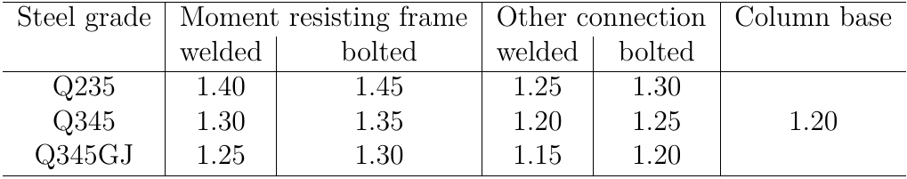
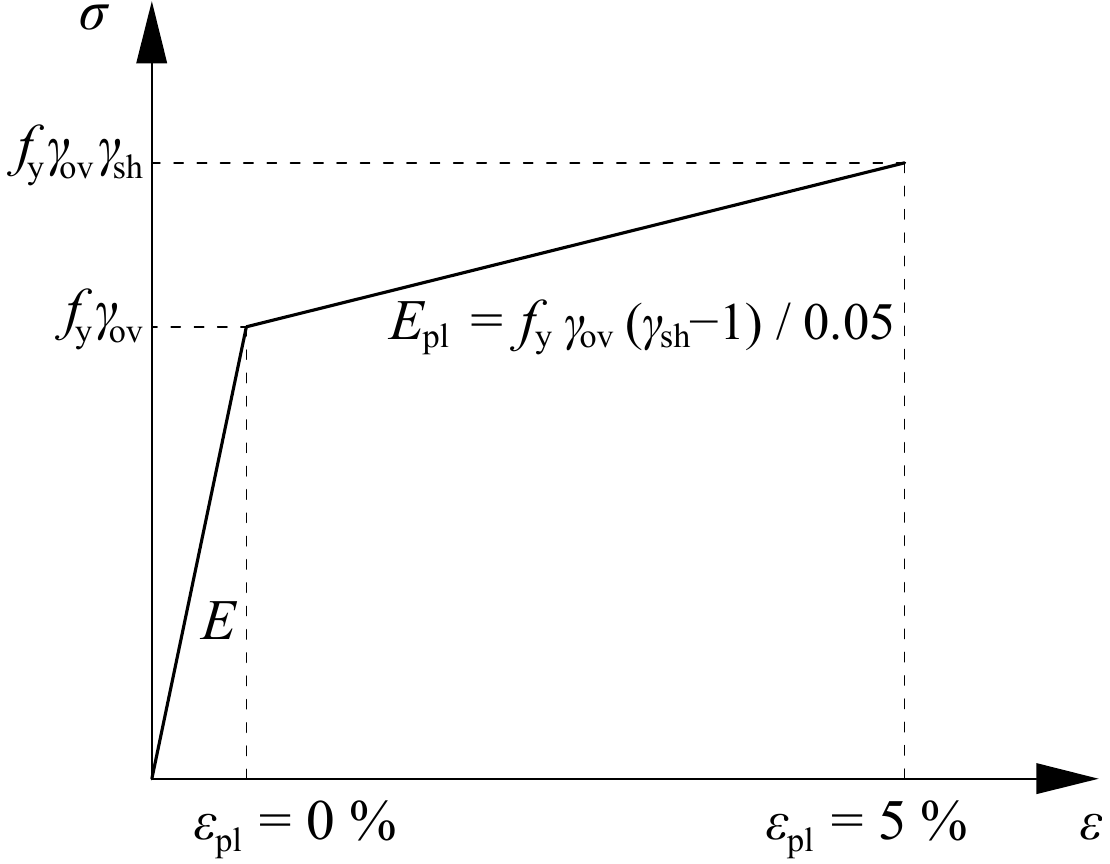
Diagrama materialului elementului disipativ