As forças nas âncoras, incluindo as forças de alavanca, são determinadas por análise de elementos finitos, mas as resistências são verificadas utilizando as disposições normativas da IS 1946:2025.
A verificação das âncoras é realizada de acordo com a IS 1946:2025. Embora a norma não forneça especificamente algumas fórmulas para âncoras moldadas no local, as mesmas fórmulas são utilizadas também para âncoras moldadas no local. Esta abordagem é considerada conservadora, uma vez que em todas as outras normas, como a ACI 318 ou a EN 1992-4, as âncoras moldadas no local apresentam uma resistência ligeiramente superior à das âncoras pós-instaladas.
Betão fendilhado ou não fendilhado pode ser selecionado nas definições do projeto. O betão fendilhado é assumido de forma conservadora como predefinição. A verificação do cone de rotura do betão à tração e ao corte pode ser ignorada nas definições do projeto, o que significa que se assume que a força é transferida através da armadura. O utilizador recebe a magnitude desta força. Devido à utilização da resistência ao cone de rotura do betão na fórmula de verificação ao arrancamento do betão por corte, esta verificação também é ignorada.
As seguintes verificações de âncoras carregadas à tração não são fornecidas e devem ser verificadas utilizando as informações constantes da Especificação Técnica do Produto relevante:
- Rotura por arranque do fixador (para todas as âncoras),
- Rotura por explosão lateral (para âncoras com cabeça),
- Rotura combinada por arranque e cone de betão (para âncoras pós-instaladas coladas),
- Rotura por fendilhamento do betão.
A rotura por arrancamento do betão ao corte também não é fornecida e deve ser verificada utilizando as informações constantes da Especificação Técnica do Produto relevante.
Rotura do aço à tração
A rotura do aço à tração é verificada de acordo com a IS 1946:2025 – 9.2.2.2:
\[N_{Rd,s} = \frac{N_{Rk,s}}{\gamma_{Ms}} \]
onde:
- \( N_{Rk,s} = A_s \cdot f_u \) – resistência característica de um fixador em caso de rotura do aço
- \( A_s \) – área de tensão de tração do parafuso de ancoragem
- \( f_u \) – resistência última do parafuso de ancoragem
- \(\gamma_{Ms} = \frac{1.2 \, f_y}{f_u} \geq 1.4 \) – coeficiente parcial de segurança para rotura do aço à tração
- \( f_y \) – tensão de cedência do parafuso de ancoragem
- \( f_u \) – resistência última do parafuso de ancoragem
Resistência ao cone de rotura do betão de uma âncora à tração
A resistência ao cone de rotura do betão de uma âncora à tração é verificada de acordo com a IS 1946:2025 – 9.2.2.3 e é fornecida para o grupo de âncoras (quando aplicável). A resistência de cálculo dos fixadores tracionados num grupo ou de um fixador individual é:
\[N_{Rd,c} = \frac{N_{Rk,c}}{\gamma_{Mc}}\]
\[N_{Rk,c} = N^{0}_{Rk,c} \cdot \frac{A_{c,N}}{A^{0}_{c,N}} \cdot \psi_{s,N} \cdot \psi_{re,N} \cdot \psi_{ec,N} \cdot \psi_{M,N}\]
onde:
- \( N^{0}_{Rk,c} = 7.2 \, \sqrt{f_{ck}} \, h_{ef}^{1.5} \) para betão fendilhado, \( N^{0}_{Rk,c} = 10.1 \, \sqrt{f_{ck}} \, h_{ef}^{1.5} \) para betão não fendilhado – resistência característica de um fixador, afastado dos efeitos de fixadores adjacentes ou de bordos do elemento de betão; a condição do betão pode ser definida nas definições do projeto
- \( f_{ck} \) – resistência característica à compressão em cubo do betão
- \( h_{ef} = \min \left[ h_{emb}, \max\left( \frac{c_{max}}{1.5}, \frac{s_{max}}{3} \right) \right] \) – profundidade de embutimento efetiva
- \(c_{\max}\) – distância máxima do centro da âncora ao bordo do elemento de betão
- \(s_{\max}\) – distância máxima entre eixos de âncoras
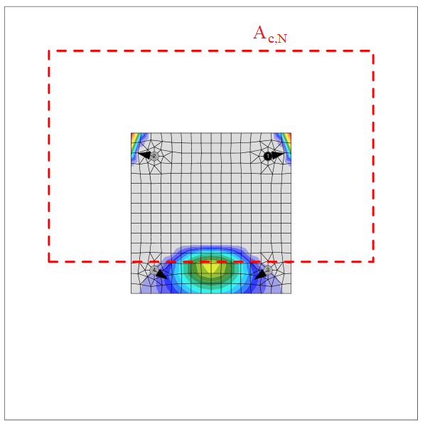
- \( A_{c,N} \) – área do cone de rotura do betão para grupo de âncoras
- \( A^{0}_{c,N} = (3.0 \, h_{ef})^2 \) – área do cone de rotura do betão para âncora individual não influenciada por bordos
- \(\psi_{s,N} = 0.7 + 0.3 \, \frac{c'}{c_{cr,N}} \leq 1\) – parâmetro relacionado com a distribuição de tensões no betão devido à proximidade do fixador a um bordo do elemento de betão
- \( c' \) – distância mínima da âncora ao bordo
- \( c'_{cr,N} = 1.5 \, h_{ef} \) – distância ao bordo característica para garantir a transmissão da resistência característica de uma âncora em caso de cone de rotura do betão sob carga de tração
- \(\psi_{re,N} = 0.5 + \frac{h_{emb}}{200} \leq 1\) – parâmetro que contabiliza o lascamento da camada superficial
- \( h_{emb} \) – profundidade de embutimento
- \(\psi_{ec,N} = \psi_{ec,N,x} \cdot \psi_{ec,N,y}\) – fator de modificação para grupos de âncoras carregados excentricamente à tração
- \(\psi_{ec,N,x} = \frac{1}{1 + \frac{2 e_{N,x}}{s_{cr,N}}}\), \(\psi_{ec,N,y} = \frac{1}{1 + \frac{2 e_{N,y}}{s_{cr,N}}}\) – fatores de modificação nas direções x e y
- \( e_{N,x}, e_{N,y} \) – excentricidades de carga
- \( s'_{cr,N} = 3.0 \, h_{ef} \) – espaçamento característico de âncoras para garantir a resistência característica das âncoras em caso de rotura por cone de betão sob carga de tração
- \(\psi_{M,N}\) – parâmetro que contabiliza o efeito de uma força de compressão entre a chapa de fixação e o betão; \(\psi_{M,N}=1.0\) se qualquer um dos seguintes critérios for satisfeito:
- \(c' < 1.5 \cdot h_{ef}\) – a âncora está localizada próxima do bordo
- \( \frac{N_c^n}{N_{Ld}} < 0.8\)
- \(\frac{z}{h_{ef}} \ge 1.5\)
- \(N_c^n\) – força de compressão na placa de base
- \(N_{Ld} \) – soma das forças de tração das âncoras com área de cone de rotura do betão comum
- \(\psi_{M,N} = 2- \frac{z}{h_{ef}} \ge 1 \) – caso contrário
- \(z\) – braço interno de alavanca
- \(\gamma_{Mc} = \gamma_c \cdot \gamma_{inst}\)
- \( \gamma_c \) – coeficiente parcial de segurança para o betão, editável nas definições do projeto
- \( \gamma_{inst} \) – coeficiente de segurança de instalação, editável nas definições do projeto
A área do cone de rotura do betão para o grupo de âncoras carregadas à tração que formam um cone de betão comum, Ac,N, é representada pela linha tracejada a vermelho.
Rotura do aço ao corte
A rotura do aço ao corte é determinada de acordo com a Cl. 9.2.3. Assume-se que a âncora é constituída por uma barra roscada com as mesmas propriedades de material que os parafusos.
Força de corte sem braço de alavanca
A resistência ao corte é verificada de acordo com a IS 1946:2025 – 9.2.3.1:
\[V_{Rd,s} = \frac{V_{Rk,s}}{\gamma_{Ms}}\]
\[V_{Rk,s} = k_1 \cdot V^{0}_{Rk,s}\]
\[V^{0}_{Rk,s} = 0.5 \cdot A_s \cdot f_u\]
onde:
- \( V_{Rk,s} \) – resistência característica de um fixador em caso de rotura do aço
- \( k_1 \) – fator dependente do produto, assumido \( k_1 = 1\)
- \( V^{0}_{Rk,s} \) – resistência característica ao corte
- \( A_s \) – área de tensão de tração
- \( f_u \) – resistência última do parafuso de ancoragem
- \( \gamma_{Ms} \) – coeficiente parcial de segurança para rotura do aço sob carga de corte
- \( \gamma_{Ms} = \frac{1.0 \, f_y}{f_u} \geq 1.25 \) para \(f_u \le 800\) MPa e \(f_y/f_u \le 0.8\)
- \( \gamma_{Ms} = 1.5\) para \(f_u > 800\) MPa ou \(f_y/f_u > 0.8\)
- \( f_y \) – tensão de cedência do parafuso de ancoragem
Força de corte com braço de alavanca
A resistência ao corte é verificada de acordo com a IS 1946:2025 – 9.2.3.2:
\[V_{Rd,s} = \frac{V_{Rk,s}}{\gamma_{Ms}}\]
\[V_{Rk,s} = \frac{\alpha_M \cdot M_{Rk,s}}{l}\]
onde:
- \( V_{Rk,s} \) – resistência característica de um fixador em caso de rotura do aço com braço de alavanca
- \( \alpha_M \) – fator que contabiliza o grau de encastramento do fixador, assumido \( \alpha_M = 2\) porque a âncora é fixada por duas porcas e a placa de base é mais rígida do que a âncora
- \( M_{Rk,s} = M^{0}_{Rk,s} \cdot \left( 1 - \frac{N_{Ld}}{N_{Rd,s}} \right) \) – resistência característica à flexão do fixador influenciada pela carga axial
- \( N_{Ld} \) – força de tração de cálculo
- \( N_{Rd,s} \) – resistência à tração de um fixador para rotura do aço
- \(M^{0}_{Rk,s} = 1.2 \cdot Z_{el} \cdot f_u\) – resistência característica à flexão do fixador
- \( Z_{el} = \frac{\pi \, d_{a,r}^3}{32} \) – módulo de secção elástico do fixador
- \( d_{a,r} \) – diâmetro da âncora reduzido pela rosca
- \( f_u \) – resistência última do parafuso de ancoragem
- \(l = 0.5 \cdot d_a + t_g + \frac{t_p}{2}\) – comprimento do braço de alavanca
- \( d_a \) – diâmetro da âncora
- \( t_g \) – espessura da camada de argamassa
- \( t_p \) – espessura da placa de base
- \( \gamma_{Ms} \) – coeficiente parcial de segurança para rotura do aço sob carga de corte
- \( \gamma_{Ms} = \frac{1.0 \, f_y}{f_u} \geq 1.25 \) para \(f_u \le 800\) MPa e \(f_y/f_u \le 0.8\)
- \( \gamma_{Ms} = 1.5\) para \(f_u > 800\) MPa ou \(f_y/f_u > 0.8\)
- \( f_y \) – tensão de cedência do parafuso de ancoragem
Rotura do betão pelo bordo
A resistência à rotura do betão pelo bordo é verificada de acordo com a IS 1946:2025 – 9.2.3.4. Se os cones de betão dos fixadores se intersetarem, são verificados como grupo. Os bordos na direção da carga de corte são verificados. Assume-se que toda a carga numa placa de base é transferida por um fixador próximo do bordo verificado.
\[V_{Rd,c} = \frac{V_{Rk,c}}{\gamma_{Mc}}\]
\[V_{Rk,c} = V^{0}_{Rk,c} \cdot \frac{A_{c,V}}{A^{0}_{c,V}} \cdot \psi_{s,V} \cdot \psi_{re,V} \cdot \psi_{ec,V} \cdot \psi_{h,V} \cdot \psi_{\alpha,V}\]
onde
- \( V^{0}_{Rk,c} \) – valor inicial da resistência característica ao corte do fixador
- \( V^{0}_{Rk,c} = 1.55 \cdot d_a^{\alpha} \cdot h_{ef}^{\beta} \cdot \sqrt{f_{ck}} \cdot (c'_1)^{1.5} \) para betão fendilhado
- \( V^{0}_{Rk,c} = 2.18 \cdot d_a^{\alpha} \cdot h_{ef}^{\beta} \cdot \sqrt{f_{ck}} \cdot (c'_1)^{1.5} \) para betão não fendilhado
- \( d_a \) – diâmetro da âncora
- \( \alpha = 0.1 \cdot \left( \frac{h_{ef}}{c'_1} \right)^{0.5} \) – fator
- \( h_{ef} = \min(h_{emb}, 20 \cdot d_a) \) – parâmetro relacionado com o comprimento do fixador
- \( h_{emb} \) – profundidade de embutimento
- \( \beta = 0.1 \cdot \left( \frac{d_a}{c'_1} \right)^{0.2} \) – fator
- \( f_{ck} \) – resistência característica à compressão em cubo do betão
- \( c'_1 \leq \max \left( \frac{c_{2,max}}{1.5}, \frac{D}{1.5}, \frac{s_{2,max}}{3} \right) \) – distância ao bordo do fixador na direção 1, em direção ao bordo na direção de carregamento
- \( D \) – espessura do elemento de betão
- \( c_{2,max} \) – a maior das duas distâncias aos bordos paralelos à direção de carregamento
- \( s_{2,max} \) – espaçamento máximo na direção 2 entre fixadores dentro de um grupo
- \(A^{0}_{c,V} = 4.5 \cdot (c'_1)^2\) – área projetada de referência do cone de rotura
- \( A_{c,V} \) – área real do corpo idealizado de rotura do betão
- \(\psi_{s,V} = 0.7 + 0.3 \cdot \frac{c'_2}{1.5 \cdot c'_1} \leq 1\) – parâmetro relacionado com a distribuição de tensões no betão devido à proximidade do fixador a um bordo do elemento de betão
- \( c'_1 \) – distância ao bordo do fixador na direção 1, em direção ao bordo na direção de carregamento
- \( c'_2 \) – distância ao bordo perpendicular à direção 1, que é a menor distância ao bordo num elemento estreito com múltiplas distâncias ao bordo
- \(\psi_{re,V} = 1.0\) – parâmetro que contabiliza o efeito de lascamento da camada superficial; assume-se que não existe armadura de bordo nem estribos
- \(\psi_{ec,V} = \frac{1}{1 + \frac{2 e_V}{3 \cdot c'_1}} \leq 1\) – fator de modificação para grupos de âncoras carregados excentricamente ao corte
- \( e_V \) – excentricidade da carga de corte
- \( \psi_{h,V} = \left( \frac{1.5 \cdot c'_1}{D} \right)^{0.5} \geq 1 \) – fator de modificação para âncoras localizadas num elemento de betão pouco espesso
- \(\psi_{\alpha,V} = \sqrt{\frac{1}{(\cos \alpha_V)^2 + (0.5 \cdot \sin \alpha_V)^2}} \geq 1\) – fator de modificação para âncoras carregadas com um ângulo em relação ao bordo do betão
- \( \alpha_V \) – ângulo entre a carga aplicada ao fixador ou grupo de fixadores e a direção perpendicular ao bordo livre em consideração
- \(\gamma_{Mc} = \gamma_c \cdot \gamma_{inst}\) – coeficiente parcial de segurança para rotura do betão
- \( \gamma_c \) – coeficiente parcial de segurança para o betão
- \( \gamma_{inst} \) – coeficiente de segurança de instalação de um sistema de ancoragem ao corte
Interação de forças de tração e corte no aço
A interação de forças de tração e corte no aço é realizada para âncoras com afastamento: Direta de acordo com a IS 1946:2025 – 9.2.4:
\[\left( \frac{N_{Ld}}{N_{Rd,s}} \right)^2 + \left( \frac{V_{Ld}}{V_{Rd,s}} \right)^2 \leq 1.0\]
onde:
- \( N_{Ld} \) – força de tração de cálculo
- \( N_{Rd,s} \) – resistência à tração do fixador
- \( V_{Ld} \) – força de corte de cálculo
- \( V_{Rd,s} \) – resistência ao corte do fixador
A interação no aço não é necessária no caso de carga de corte com braço de alavanca. É coberta pela equação de carga de corte com braço de alavanca.
Interação de forças de tração e corte no betão
A interação de forças de tração e corte no betão é verificada de acordo com a IS 1946:2025 – 9.2.4:
\[\left( \frac{N_{Ld}}{N_{Rd,i}} \right)^{1.5} + \left( \frac{V_{Ld}}{V_{Rd,i}} \right)^{1.5} \leq 1.0\]
onde:
- \( \frac{N_{Ld}}{N_{Rd,i}} \) – o maior valor de utilização para modos de rotura à tração
- \( \frac{V_{Ld}}{V_{Rd,i}} \) – o maior valor de utilização para modos de rotura ao corte
- \( \frac{N_{Ld,g}}{N_{Rd,c}} \) – rotura por cone de betão de âncora à tração
- \( \frac{V_{Ld,g}}{V_{Rd,c}} \) – rotura do betão pelo bordo
Âncoras com afastamento: Folga
As âncoras com afastamento: folga à tração são dimensionadas de acordo com a IS 1946:2025, e as âncoras à compressão são dimensionadas como um elemento de barra de acordo com a IS 800: 2007 com coeficiente parcial de segurança das âncoras. O comprimento assumido do elemento é a soma da altura da folga, metade da espessura do diâmetro nominal e metade da espessura da placa de base. As âncoras com afastamento são geralmente verificadas numa fase de construção antes da injeção de argamassa.
A rotura do aço à tração é verificada de acordo com a IS 1946:2025 – 9.2.2.2:
\[N_{Rd,s} = \frac{N_{Rk,s}}{\gamma_{Ms}} \]
A rotura do aço à compressão é verificada de acordo com a IS 800:2007 – 7.1:
\[P_d = A_s \cdot f_{cd}\]
onde:
- \( A_s \) – área da âncora reduzida pela rosca
- \( f_{cd} = \frac{\chi \cdot f_u}{\gamma_{Ms}} \) – tensão de compressão de cálculo
- \(\chi = \min \left( \frac{1}{\phi + \sqrt{\phi^2 - \lambda^2}}, 1 \right)\) – fator de redução à encurvadura
- \(\phi = 0.5 \cdot \left[ 1 + \alpha \cdot (\lambda - 0.2) + \lambda^2 \right]\) – valor para determinar o fator de redução à encurvadura
- \( \alpha \) – fator de imperfeição
- \(\lambda = \sqrt{\frac{f_u}{f_{cc}}}\) – esbelteza relativa
- \(f_{cc} = \frac{\pi^2 \cdot E}{\left( \frac{K L}{r} \right)^2}\) – tensão de encurvadura de Euler
- \( E \) – módulo de elasticidade
- \(K L = 2 \cdot l\) – comprimento de encurvadura
- \( l = 0.5 \cdot d_a + t_g + \frac{t_p}{2} \) – comprimento do braço de alavanca
- \( d_a \) – diâmetro da âncora
- \( t_g \) – espessura da camada de argamassa
- \( t_p \) – espessura da placa de base
- \(r = \sqrt{\frac{I}{A_s}}\) – raio de giração do parafuso de ancoragem
- \( I = \frac{\pi \cdot d_{a,r}^4}{64} \) – momento de inércia do parafuso
- \( d_{a,r} \) – diâmetro da âncora reduzido pela rosca
- \(\gamma_{Ms} = \frac{1.2 \, f_y}{f_u} \geq 1.4 \) – coeficiente parcial de segurança para rotura do aço sob carga de tração
- \( f_y \) – tensão de cedência do parafuso de ancoragem
- \( f_u \) – resistência última do parafuso de ancoragem
A resistência ao corte é verificada de acordo com a IS 1946:2025 – 9.2.3.1:
\[V_{Rd,s} = \frac{V_{Rk,s}}{\gamma_{Ms}}\]
\[V_{Rk,s} = k_1 \cdot V^{0}_{Rk,s}\]
\[V^{0}_{Rk,s} = 0.5 \cdot A_s \cdot f_u\]
A resistência à flexão é verificada de acordo com a IS 1946:2025 – 9.2.3.2:
\[M_{Rd,s} = \frac{M_{Rk,s}}{\gamma_{Ms}}\]
onde:
- \( M^{0}_{Rk,s} = 1.2 \cdot Z_{el} \cdot f_u \) – resistência característica à flexão do fixador
- \( Z_{el} = \frac{\pi \cdot d_{a,r}^3}{32} \) – módulo de secção elástico do fixador
- \( d_{a,r} \) – diâmetro da âncora reduzido pela rosca
- \(\gamma_{Ms} = \frac{1.0 \, f_y}{f_u} \geq 1.25\)
- \( f_y \) – tensão de cedência do parafuso de ancoragem
- \( f_u \) – resistência última do parafuso de ancoragem
Interação de carregamento para âncoras à tração (IS 1946:2025 – 9.2.4):
\[\frac{N_{Ld}}{N_{Rd,s}} + \frac{M_{Ld}}{M_{Rd,s}} \leq 1.0\]
onde:
- \( N_{Ld} \) – força de tração de cálculo
- \( N_{Rd,s} \) – resistência à tração de cálculo
- \( M_{Ld} \) – momento fletor de cálculo
- \( M_{Rd,s} \) – resistência à flexão de cálculo
Interação de carregamento para âncoras à compressão (IS 1946:2025 – 9.2.4):
\[\frac{P}{P_d} + \frac{M_{Ld}}{M_{Rd,s}} \leq 1.0\]
onde:
- \( P \) – força de compressão de cálculo
- \( P_d \) – resistência à compressão de cálculo
- \( M_{Ld} \) – momento fletor de cálculo
- \( M_{Rd,s} \) – resistência à flexão de cálculo
Os modos de rotura relacionados com o betão, incluindo a sua interação, são verificados como para as âncoras correntes de acordo com a IS 1946:2025.
Pormenorização
Se forem utilizadas âncoras com \(f_u \ge 1000\) MPa, a resistência do aço para carga de corte pode não ser precisa; utilize a resistência do aço proveniente do AR.