
Check of steel connection components (SP)
CBFEM method combines the advantages of the general Finite Element Method (FEM) and standard Component Method (CM). The stresses and internal forces calculated on the accurate CBFEM model are used in checks of all components – Bolts, preloaded bolts, and welds which are checked according to SP 16.13330.2017. The concrete in bearing is checked according to SP 63.13330.2012. The plates are checked by finite element analysis. The checks of anchorage have not yet been implemented in the current version.
Normtoetsing van staalplaten volgens Russische normen
De rekcontrole wordt uitgevoerd op schaaleindige elementen die platen simuleren. De vloeigrens wordt gedeeld door de factor voor materiaalsterkte en vermenigvuldigd met de gebruiksfactor.
De resulterende equivalente spanning (HMH, von Mises) en plastische rek worden berekend op platen. Wanneer de vloeigrens (gedeeld door de partiële veiligheidsfactor voor materiaalsterkte, γm – SP 16, Tabel 3, en vermenigvuldigd met de gebruiksfactor γc – SP 16, Tabel 1, die bewerkbaar is in de norminstellingen, SP 16, Art. 11.1.1) op het bilineaire materiaaldiagram wordt bereikt, wordt de controle van de equivalente plastische rek uitgevoerd. De grenswaarde van 5 % wordt voorgesteld in Eurocode (EN 1993-1-5 App. C, Par. C8, Noot 1). Deze waarde kan worden aangepast in de norminstellingen, maar verificatiestudies zijn uitgevoerd voor deze aanbevolen waarde. De materiaaleigenschappen van de staaf worden bepaald door de dikste plaat.
\[ \frac{1}{R_y \gamma_c} \sqrt{\sigma_x^2-\sigma_x \sigma_y + \sigma_y^2 + 3 \tau_{xy}^2} \le 1.0 \]
Het plaatelement wordt verdeeld in vijf lagen, en het elastisch/plastisch gedrag wordt in elk ervan onderzocht. Het programma toont het maatgevende resultaat van alle lagen.
De spanning kan iets hoger zijn dan de rekenwaarde van de vloeigrens. De reden is de lichte helling van de plastische tak van het spanning-rek diagram, die in de berekening wordt gebruikt om de stabiliteit van de berekening te verbeteren.
Normtoetsing van bouten en voorspanbouten volgens Russische normen
Bouten
Bouten worden gecontroleerd volgens SP 16, Art. 14.2. De trek kracht en afschuivingskracht in elke bout worden bepaald door eindige elementenanalyse. Wrikkrachten worden bepaald door eindige elementenanalyse en in rekening gebracht. Elk afschuivingsvlak wordt afzonderlijk gecontroleerd. De spijkerplaat wordt gecontroleerd op de som van de afschuivingskrachten in nabijgelegen vlakken.
Bout op afschuiving
Een bout belast door een rekenwaarde van de afschuivingskracht wordt ontworpen volgens Art. 14.2.9 en moet voldoen aan:
\[ N_s \le N_{bs} = R_{bs} A_b \gamma_b \gamma_c \]
waarbij:
- Ns – afschuivingskracht in één vlak van een bout
- Nbs – afschuivingsweerstand van de bout
- Rbs – rekenwaarde van de afschuivingssterkte van een bout – SP 16, Tabel 5
- Ab – bruto doorsnede-oppervlak van de bout
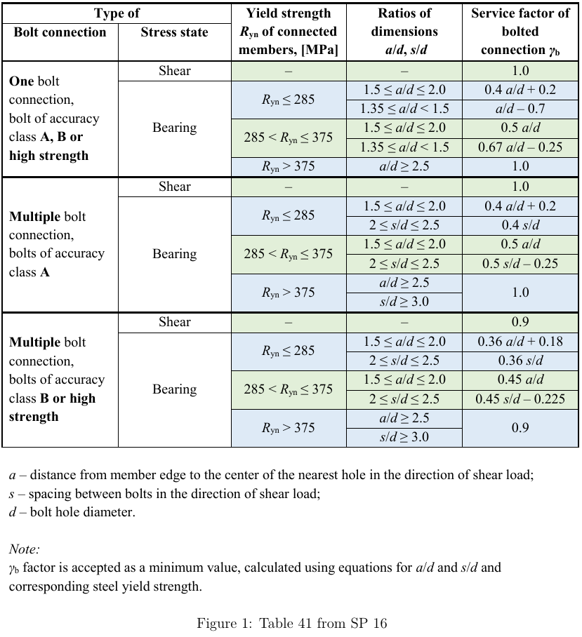
- γb – gebruiksfactor van de boutverbinding – SP 16, Tabel 41 – γb = 1,0 voor enkelvoudige boutverbinding en meervoudige boutverbinding met nauwkeurigheidsklasse A, γb = 0,9 voor meervoudige boutverbinding en nauwkeurigheidsklasse B en hoogsterkte bouten (Rbun ≥ 800 MPa)
- γc – gebruiksfactor – SP 16, Tabel 1, aanpasbaar in de norminstellingen
| Rbyn [MPa] | Rbs [MPa] |
| \(R_{byn} \le 300 \) | \(0.42 \cdot R_{bun} \) |
| \(300 < R_{byn} \le 400 \) | \(0.41 \cdot R_{bun} \) |
| \(400 < R_{byn} \le 936 \) | \(0.40 \cdot R_{bun} \) |
| \(936 > R_{byn} \) | \(0.35 \cdot R_{bun} \) |
Elk afschuivingsvlak wordt afzonderlijk gecontroleerd.
Bout op trek
Een bout belast door een rekenwaarde van de trek kracht wordt ontworpen volgens SP 16, Art. 14.2.9 en moet voldoen aan:
\[ N_t ≤ N_{bt} = R_{bt} A_{bn} \gamma_c \]
waarbij:
- Nt – trek kracht in een bout
- Nbt – trekweerstand van de bout
- Rbt – rekenwaarde van de treksterkte – SP 16, Tabel 5
- Abn – netto doorsnede-oppervlak van een bout
- γc – gebruiksfactor – SP 16, Tabel 1, aanpasbaar in de norminstellingen
| Rbun [MPa] | Rbt [MPa] |
| \(R_{bun} < 830 \) | \(0.45 \cdot R_{bun} \) |
| \(830 \le R_{bun} < 1040 \) | \(0.54 \cdot R_{bun} \) |
| \(R_{bun} \ge 1040 \) | \(0.70 \cdot R_{bun} \) |
Bout belast door gecombineerde afschuiving en trek
Een bout gelijktijdig belast door afschuivings- en trekkrachten wordt ontworpen volgens SP 16, Art. 14.2.13 en moet voldoen aan:
\[ \sqrt{\left ( \frac{N_t}{N_{bt}} \right ) ^2 + \left ( \frac{N_s}{N_{bs}} \right ) ^2} \le 1.0 \]
waarbij:
- Nt – trek kracht in een bout
- Nbt – trekweerstand van de bout
- Ns – afschuivingskracht in één vlak van een bout
- Nbs – afschuivingsweerstand van de bout
Bouten op spijkerdruk
Een plaat belast door een spijkerdruk kracht ten gevolge van een bout op afschuiving wordt ontworpen volgens SP 16, Art. 14.2.9 en moet voldoen aan:
\[ N_s ≤ N_{bp} = R_{bp} d_b t \gamma_b \gamma_c \]
waarbij:
- Ns – afschuivingskracht in een bout die aangrijpt op een plaat
- Nbp – spijkerdrukweerstand van een plaat
- Rbp – rekenwaarde van de spijkerdruksterkte; Rbp = 1,6 · Ru voor nauwkeurigheidsklasse A en Rbp = 1,35 · Ru voor nauwkeurigheidsklasse B – SP 16, Tabel 5
- Run – treksterkte van het verbonden element
- db – boutdiameter
- t – dikte van de plaat
- γb – gebruiksfactor van de boutverbinding – SP 16, Tabel 41
- γc – gebruiksfactor – SP 16, Tabel 1, aanpasbaar in de norminstellingen
Elke plaat wordt afzonderlijk gecontroleerd en het maatgevende geval wordt weergegeven. SP 16 geeft geen gebruiksfactor voor boutverbindingen, γb, voor gevallen buiten de detailleringsgrenzen. Daarom wordt de spijkerdrukcontrole voor dergelijke gevallen niet uitgevoerd.
Wrijvingsverbindingen
Voor wrijvingsverbindingen moet glijding worden beperkt en gecontroleerd volgens SP 16, Art. 14.3. Deze bouten moeten ook worden gecontroleerd als spijkerdrukverbinding voor de uiterste grenstoestand na het optreden van glijding. Een bout belast door een afschuivingskracht moet voldoen aan:
\[ N_s \le N_{bf} = Q_{bh} \gamma_b \gamma_c \]
waarbij:
- Ns – afschuivingskracht op één voorspanbout en één wrijvingsvlak
- Nbf – glijweerstand van één voorspanbout en één wrijvingsvlak
- Qbh = Rbh Abn μ / γh – rekenwaarde van de glijweerstand van één voorspanbout en één wrijvingsvlak
- Rbh = 0,7 · Rbun – rekenwaarde van de voorspankracht in de voorspanbout – SP 16, Art. 6.7
- Rbun – treksterkte van de bout
- Abn – trekspanningsoppervlak
- μ – wrijvingscoëfficiënt voor voorspanbouten – SP 16, Tabel 42, aanpasbaar in de norminstellingen
- γh – coëfficiënt bij het aanspannen van bouten – SP 16, Tabel 42
- Normale gaten: statische belasting, Δ ≤ 4 mm; dynamische belasting, Δ ≤ 1 mm:
- γh = 1,12 voor μ ≥ 0,42
- γh = 1,17 voor 0,35 ≤ μ < 0,42
- γh = 1,30 voor μ < 0,35
- Oversized gaten: statische belasting, Δ > 4 mm; dynamische belasting, Δ > 1 mm:
- γh = 1,70 voor μ < 0,35
- γh = 1,35 voor μ ≥ 0,35
- Normale gaten: statische belasting, Δ ≤ 4 mm; dynamische belasting, Δ ≤ 1 mm:
- Δ – verschil tussen de diameter van het boutgat en de diameter van de bout
- γb – gebruiksfactor van de wrijvingsverbinding – SP 16, Art. 14.3.4
- γc – gebruiksfactor – SP 16, Tabel 1, aanpasbaar in de norminstellingen
Statische of dynamische belasting kan worden ingesteld in de norminstellingen.
| Aantal bouten n | \( \gamma_b \) |
| \( n < 5 \) | 0,8 |
| \( 5 \le n < 10 \) | 0,9 |
| \( n \ge 10 \) | 1,0 |
Het aantal effectieve contactvlakken, κ, is altijd gelijk aan 1, omdat elk contactvlak afzonderlijk wordt gecontroleerd.
Volgens SP 16, Art. 14.3.6, voor bouten in wrijvingsverbindingen belast door gecombineerde afschuiving en trek, wordt de gebruiksfactor van de wrijvingsverbinding, γb, vermenigvuldigd met:
\[ \gamma_b = \gamma_b \cdot \left ( 1 - \frac{N_t}{P_b} \right ) \]
waarbij:
- Nt – trek kracht in een bout
- Pb = Rbh Abn – voorspankracht in een bout
- Rbh = 0,7 · Rbun – rekenwaarde van de voorspankracht in de voorspanbout – SP 16, Art. 6.7
- Abn – trekspanningsoppervlak
Wrijvingsverbindingen moeten ook worden gecontroleerd voor de uiterste grenstoestand. Het bouttype moet worden gewijzigd naar spijkerdruk – trek/afschuiving interactie, de belastingen moeten dienovereenkomstig worden verhoogd en de verbinding moet opnieuw worden gecontroleerd.
Normtoetsing van lassen volgens Russische normen
Het is mogelijk om stompe lassen of hoeklassen in te stellen over de volledige randlengte, gedeeltelijke lassen of onderbroken lassen. Stompe lassen worden verondersteld dezelfde sterkte te hebben als de gelaste staaf en worden niet gecontroleerd. Bij hoeklassen wordt het laselement ingevoegd tussen interpolatiekoppelingen die platen met elkaar verbinden. Het laselement heeft een gespecificeerd elasto-plastisch materiaaldiagram om de spanning over de laslengte te herverdelen, zodat lange lassen, lassen in meerdere richtingen of lassen aan een niet-verstijfde flens een vergelijkbare weerstand hebben als bij handberekening. Het meest belaste laselement is bepalend bij de lascontrole.
Het meest belaste hoeklaselement van de las wordt gecontroleerd volgens SP 16, Art. 14.1. De lengte van de las dient te worden verminderd met 10 mm volgens SP 16, Art. 14.1.16.
Controle lasmateriaal:
\[ \frac{N}{\beta_f k_f l_{we} R_{wf} \gamma_c} ≤ 1.0 \]
Controle basismateriaal:
\[ \frac{N}{\beta_z k_f l_{we} R_{wz} \gamma_c} ≤ 1.0 \]
waarbij:
- N – kracht werkend op een laselement
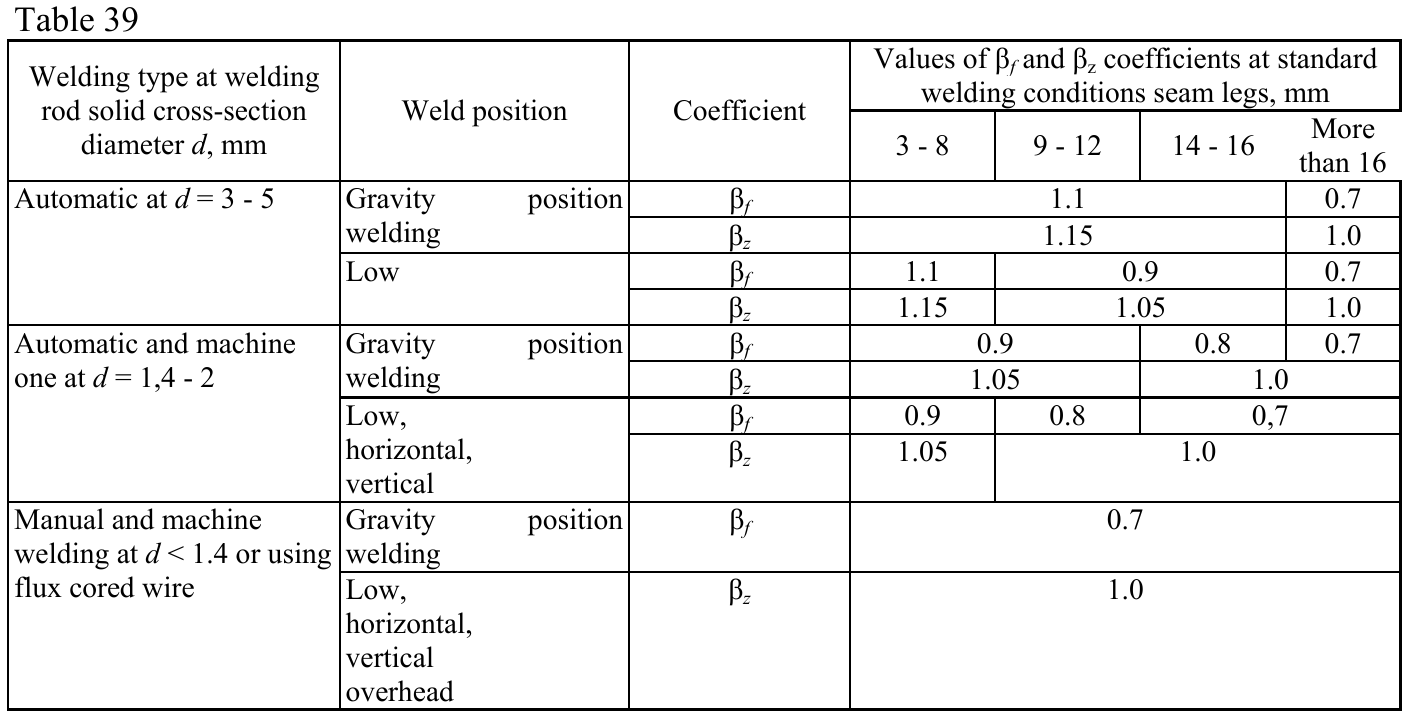
- βf – coëfficiënt voor lasmateriaal uit SP 16, Tabel 39; de coëfficiënt wordt bepaald door de norminstellingen – type lassen en laspositie (instellingen van lasmateriaal)
- βz – coëfficiënt voor basismateriaal uit SP 16, Tabel 39; de coëfficiënt wordt bepaald door de norminstellingen – type lassen en laspositie (instellingen van lasmateriaal)
- kf – lasnaadgrootte, de verhouding van de hoeklasnaad wordt aangenomen als 1:1
- \( l_{we} = \frac{l_w}{l} \cdot l_e \) – rekenkundige laselement lengte
- lw = l – 10 mm – rekenkundige laslengte
- l – werkelijke laslengte
- le – werkelijke laselement lengte
- \( R_{wf} = 0.55 \frac{R_{wun}}{\gamma_{wm}} \) – treksterkte lasmateriaal – SP 16, Tabel 4
- Rwz = 0.45 Run – treksterkte basismateriaal – SP 16, Tabel 4
- γc – gebruiksfactor – SP 16, Tabel 1, aanpasbaar in norminstellingen
- Rwun – karakteristieke sterkte van hoeklasmateriaal uit SP 16, Tabel D2
- γwm – partiële veiligheidsfactor voor lasmateriaal, γwm = 1.25 voor Rwun ≤ 490 MPa en γwm = 1.35 anders – SP 16, Tabel 4
- Run – karakteristieke sterkte van het verbonden staal
| Lasmateriaal | Rwun [MPa] | Rwf [MPa] |
| E42 | 410 | 180 |
| E46 | 450 | 200 |
| E50 | 490 | 215 |
| E60 | 590 | 240 |
| E70 | 685 | 280 |
| E85 | 835 | 340 |
Het type laspositie (zwaartelijn) kan worden ingesteld bij de selectie van de laselectrode en het lastype in de norminstellingen.
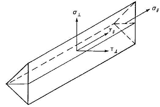
De lasdiagrammen tonen de spanning volgens de volgende formule:
\[ \sigma = \sqrt{ \sigma_{\perp}^2 + \tau_{\perp}^2 + \tau_{\parallel}^2 } \]
Normtoetsing van betonblok volgens Russische normen
Beton onder druk
Beton onder druk onder de voetplaat wordt getoetst volgens SP 63.13330.2012, Art. 8.1.44 – Berekening van gewapend-betonconstructies voor plaatselijke druk:
\[ N \le \psi R_{b,loc} A_{b,loc} \]
waarbij:
- N – plaatselijke druk kracht ten gevolge van een uitwendige belasting
- ψ – factor gelijk aan 0,75 bij niet-uniforme verdeling van de plaatselijke belasting over het oplegvlak
- Rb,loc = φb Rb – rekenwaarde van de druksterkte van beton bij plaatselijke inwerking van een druk kracht
- \( \varphi_b = 0.8 \sqrt{\frac{A_{b,max}}{A_{b,loc}}} \) en 1,0 ≤ φb ≤ 2,5 – concentratiefactor die rekening houdt met de drieassige spanningstoestand in het beton
- Rb = Rbn / γb – rekenwaarde van de axiale druksterkte van beton
- Rbn – normatieve axiale druksterkte van beton
- γb = 1,3 – betrouwbaarheidsfactor voor beton onder druk; aanpasbaar in de norminstellingen
- Ab,loc – aangrijpingsvlak van de druk kracht (oplegoppervlak) bepaald met de Eindige Elementen Methode als het contactoppervlak tussen de voetplaat en het betonblok
- Ab,max – maximaal rekenoppervlak vastgesteld op basis van de volgende regels:
- zwaartepunten van de oppervlakken Ab,loc en Ab,max vallen samen
- het maximale rekenoppervlak is meetkundig gelijkvormig aan het aangrijpingsvlak; de hellingen bedragen 1 verticaal op 2 horizontaal.
Overdracht van afschuiving
De afschuivingskracht op de voetplaat wordt verondersteld te worden overgedragen van de kolom naar de betonnen fundering door middel van:
- Wrijving tussen voetplaat en beton / mortellaag
- Afschuif deuvel
- Ankerbouten
Ankers
De trek krachten in de ankers omvatten wrikkrachten en worden bepaald door middel van eindige-elementenanalyse.
Ankers worden niet getoetst in de software.
Detaillering van bouten en lassen volgens Russische normen
Bouten
Minimale hartafstand en minimale randafstand worden gecontroleerd volgens SP 16, Tabel 40.
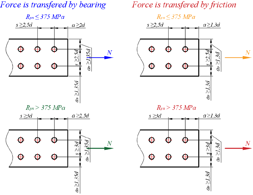
Minimale hartafstand is 2,5 · d voor staal met Ryn ≤ 375 MPa en 3 · d anders.
Minimale randafstand is 2 · d voor staal met Ryn ≤ 375 MPa en 2,5 · d anders in de richting van de afschuivingsbelasting. Minimale randafstand is 1,35 · d in de richting loodrecht op de afschuivingsbelasting. Minimale randafstanden kunnen onder bepaalde omstandigheden kleiner zijn, zoals gespecificeerd in SP 16, Tabel 40. Als aan deze voorwaarden is voldaan, kan de gebruiker de detailleringscontrole deactiveren. De controle van bouten op drukspanning mag dan echter niet worden uitgevoerd.
Voorgespannen bouten
Minimale hartafstand en minimale randafstand worden gecontroleerd volgens SP 16, Tabel 40.
Minimale hartafstand is 2,5 · d voor staal met Ryn ≤ 375 MPa en 3 · d anders.
Minimale randafstand is 1,3 · d.
Ankers
De onderlinge afstand tussen ankers moet groter zijn dan zes maal de ankerdiameter. Deze waarde is afhankelijk van het ankertype en kan worden aangepast in de Norminstellingen.
Minimale randafstand van de plaat volgt de regels voor bouten.
Lassen
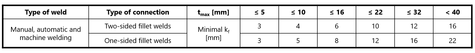
De detaillering van lassen wordt gecontroleerd volgens SP 16, Art. 14.1.7. De maximale hoeklasmaat, kf,max, moet kleiner zijn dan 1,2 · tmin, waarbij tmin de dikte is van de dunste verbonden plaat. De minimale hoeklasmaat, kf,min, wordt gecontroleerd volgens SP 16, Tabel 38. Dikte tmax is de dikste van de te lassen platen.
- Voor \(t_{min} < 0.6 \cdot t_{max}\) – kf,min = tmin voor eenzijdige hoeklas en \( k_{f,min} = t_{min} / \sqrt{2} \) voor tweezijdige hoeklas
- Voor \(t_{min} \ge 0.6 \cdot t_{max}\) – kf,min wordt geselecteerd uit de onderstaande tabel
Verbindingsclassificatie volgens Russische normen
Verbindingen worden geclassificeerd op basis van verbindingsstijfheid in:
- Stijf – verbindingen met verwaarloosbare verandering van de oorspronkelijke hoeken tussen staven,
- Flexibel – verbindingen waarvan wordt aangenomen dat ze een betrouwbare en bekende mate van buiginklemming kunnen leveren,
- Scharnierend – verbindingen die geen buigmomenten ontwikkelen.
Verbindingen worden geclassificeerd volgens EN 1993-1-8 – Cl. 5.2.2.
- Stijf – \( \frac{S_{j,ini} L_b}{E I_b} \ge k_b \)
- Flexibel – \( 0.5 < \frac{S_{j,ini} L_b}{E I_b} < k_b \)
- Scharnierend – \( \frac{S_{j,ini} L_b}{E I_b} \le 0.5 \)
waarbij:
- Sj,ini – beginstijfheid van de verbinding; de verbindingsstijfheid wordt als lineair beschouwd tot 2/3 van Mj,Rd
- Lb – theoretische lengte van de geanalyseerde staaf; ingesteld in de staaf-eigenschappen
- E – elasticiteitsmodulus (Young's modulus)
- Ib – traagheidsmoment van de geanalyseerde staaf
- kb = 8 voor raamwerken waarbij het schoorssysteem de horizontale verplaatsing met ten minste 80 % vermindert; kb = 25 voor andere raamwerken, mits in elke verdieping Kb/Kc ≥ 0.1. De waarde kb = 25 wordt gebruikt tenzij de gebruiker "geschoord systeem" instelt in de norminstelling.
- Mj,Rd – rekenwaarde van de momentweerstand van de verbinding
- Kb = Ib / Lb
- Kc = Ic / Lc
Capaciteitsontwerp volgens Russische normen
Capaciteitsontwerp gebruikt dezelfde procedure als in EC vanwege het ontbreken van voorschriften in Russische normen.
Het doel van capaciteitsontwerp is te bevestigen dat een gebouw een gecontroleerd ductiel gedrag vertoont om instorting bij een maatgevende aardbeving te voorkomen. Er wordt verwacht dat een plastisch scharnier optreedt in het dissiperende element en alle niet-dissiperende elementen van de verbinding moeten de krachten als gevolg van vloeien in het dissiperende element veilig kunnen overdragen. Het dissiperende element is gewoonlijk een balk in een momentvast raamwerk, maar het kan ook bijvoorbeeld een kopplaat zijn. De gebruiksfactor wordt niet toegepast op dissiperende elementen. Twee factoren worden toegewezen aan het dissiperende element:
- γov – oversterkte factor – EN 1998-1, Art. 6.2; de aanbevolen waarde is γov = 1,25; aanpasbaar in materialen
- γsh – rek-verhardingsfactor; de aanbevolen waarden zijn γsh = 1,2 voor een balk in een momentvast raamwerk, γsh = 1,0 anders; aanpasbaar in bewerking
Het materiaaldiagram wordt aangepast volgens de volgende figuur:
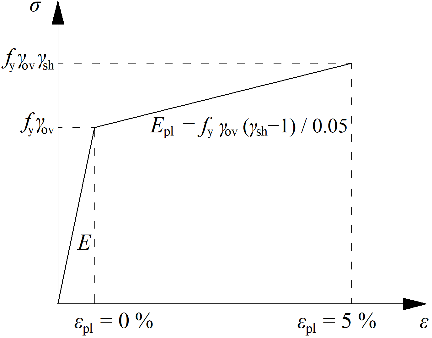
De verhoogde sterkte van het dissiperende element maakt het mogelijk belastingen in te voeren die ervoor zorgen dat het plastisch scharnier optreedt in het dissiperende element. In het geval van een momentvast raamwerk met een balk als dissiperend element, dient de balk belast te worden met My,Ed = γovγshfyWpl,y en de bijbehorende dwarskracht Vz,Ed = –2 My,Ed / Lh, waarbij:
- fy – karakteristieke vloeigrens
- Wpl,y – plastisch weerstandsmoment
- Lh – afstand tussen plastische scharnieren op de balk
In het geval van een asymmetrische verbinding dient de balk belast te worden met zowel positieve als negatieve buigmomenten en de bijbehorende dwarskrachten.
De platen van dissiperende elementen zijn uitgesloten van normtoetsing.