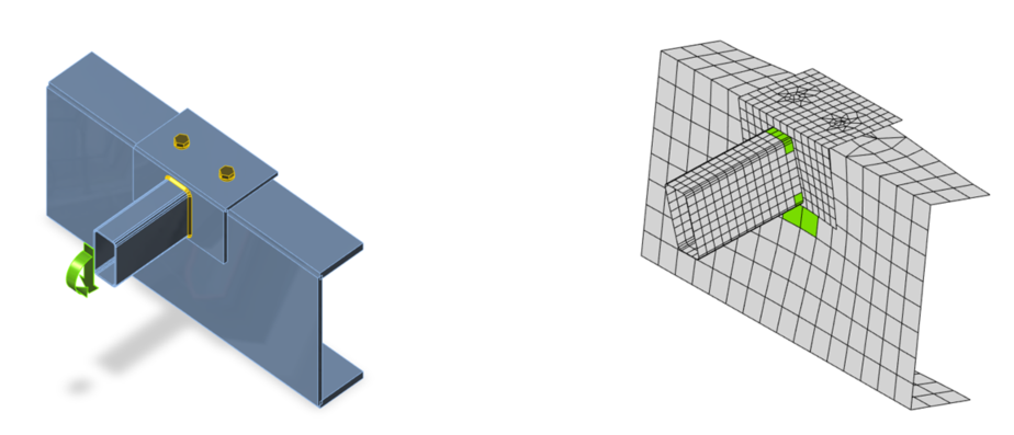
Rigidezza e capacità di deformazione
La versione 7 fornisce una nuova funzione che analizza la rigidezza e la capacità di un collegamento di qualsiasi elemento nel giunto. Il diagramma completo viene generato automaticamente, è visualizzato direttamente nell'interfaccia grafica e può essere aggiunto al report di output. La rigidezza rotazionale o assiale può essere studiata per carichi di progetto specifici. IDEA StatiCa Connection è in grado di gestire anche l'influenza di altre forze interne.
Il diagramma mostra:
- Livello del carico di progetto
- Il valore limite della capacità del collegamento per una deformazione equivalente del 5%
- Valore limite della capacità dell'elemento collegato (utile anche per la progettazione sismica)
- 2/3 della capacità limite per il calcolo della rigidezza iniziale
- Valore della rigidezza iniziale
- Limiti per la classificazione del collegamento – rigido e cernierato


Piastra di base, ancoraggio
La V7 offre la possibilità di inserire diversi offset del blocco di calcestruzzo sui diversi bordi della piastra di base in acciaio. Gli offset influenzano il calcolo delle dimensioni dei coni di rottura.

L'estremità degli ancoraggi viene spesso modificata per aumentare la coesione e ampliare il cono di rottura. Tuttavia, nelle verifiche viene considerata solo nella dimensione del cono di rottura. Gli utenti possono definire rondelle di dimensioni specifiche per aumentare il cono di rottura. La rondella può essere rettangolare o circolare, ma entrambe hanno la stessa influenza sulla dimensione del cono.
Rondelle rettangolari Rondelle circolari

Elementi di irrigidimento
Gli utenti di IDEA StatiCa Connection possono rinforzare i giunti in acciaio con piastre aggiuntive – irrigidimenti, nervature, raddoppiatori. Nella versione 7 è possibile utilizzare segmenti di profili laminati a caldo o formati a freddo per l'irrigidimento. Questi elementi di irrigidimento si comportano nel giunto allo stesso modo degli elementi in acciaio di base – tutte le operazioni di lavorazione possono essere applicate ad essi. Gli elementi di irrigidimento non possono ricevere carichi. Non fanno parte del modello globale 3D della struttura.


Contatti
Il collegamento in acciaio è modellato come un sistema di piastre (gli elementi sono composti da piastre), saldature, bulloni e contatti. I contatti compaiono nei punti in cui due piastre sono a contatto. Assorbono il 100% della pressione ma non agiscono affatto in trazione. I contatti vengono generati automaticamente tra le piastre che fanno parte di un collegamento bullonato. La versione 7 introduce la possibilità di definire il contatto tra qualsiasi coppia di superfici di piastre anche se non sono bullonate insieme. Grazie a questa nuova funzionalità è possibile risolvere numerosi problemi tecnici pratici.

Contatti tra anima e ali di 2 sezioni Z sovrapposte
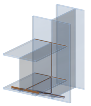
Profilo aggiunto, bullonato sull'ala superiore, contatto sull'anima

Elemento di irrigidimento, ala supportata da contatto, nessuna forza di taglio nei bulloni.
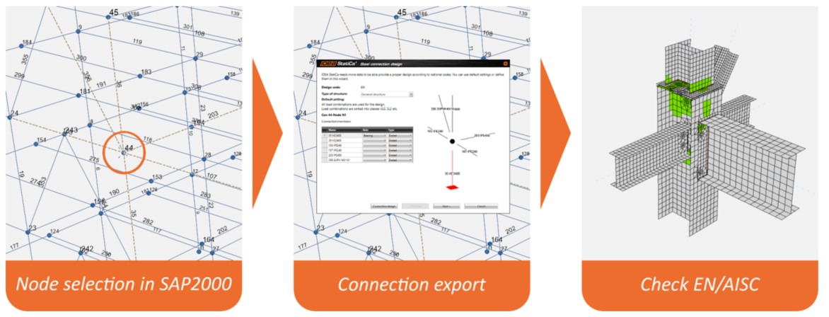
Collegamento con SAP2000
SAP2000 è un software strutturale FEA ampiamente utilizzato. IDEA StatiCa 7.0 è in grado di leggere tutti i dati necessari per la progettazione dei giunti in acciaio dai modelli 3D di SAP2000. IDEA StatiCa può leggere l'intero progetto SAP2000 o solo una sua parte. Per IDEA StatiCa Connection è disponibile un flusso di lavoro diretto semplificato: è sufficiente selezionare un nodo in SAP2000, fare clic sul plug-in "IDEA Connection" e progettare il giunto.
Miglioramenti
Modello delle saldature
Le saldature sono una parte importante di qualsiasi giunto in acciaio. Nella versione 6 viene utilizzato un modello in cui la saldatura è modellata come un vincolo tra il bordo e la superficie delle piastre. Il vincolo stesso non ha proprietà del materiale. IDEA StatiCa calcola le forze nei vincoli e offre la valutazione mediante 3 metodi: massimo/medio/lineare. Il team di sviluppo di IDEA StatiCa ha lavorato a un modello molto più preciso, in cui anche le saldature sono dotate di proprietà del materiale. Ciò significa che possono diventare plastiche come tutte le piastre in acciaio. Questo modello fornirà risultati migliori, in particolare per le saldature lunghe. L'effetto denominato "lunghezza efficace della saldatura" sarà già preso in considerazione nei risultati calcolati. Le saldature plastiche saranno disponibili una volta completato un approfondito processo di sviluppo e test, e comunque non oltre il 1° ottobre 2016.
Cosa è stato migliorato per le saldature già nella versione 7: la geometria della posizione della saldatura è stata ricostruita. La lunghezza reale della saldatura viene rispettata in caso di lunghezze diverse dei bordi saldati o in caso di interruzione delle saldature dovuta ad aperture. La posizione precisa delle saldature ci offre la possibilità di migliorare la presentazione delle saldature. Le saldature vengono renderizzate come nella realtà quando si utilizza la modalità "solido". Quando si utilizza la modalità "trasparente", vengono mostrati solo i vincoli lineari tra bordo e superficie. Ciò consente di verificare facilmente la corretta implementazione della saldatura. La nuova geometria ha contribuito a migliorare il comportamento delle saldature vicine al bordo della piastra, dove IDEA StatiCa può fornire risultati non simmetrici in problemi simmetrici. Grazie a questa correzione e miglioramento, i risultati della versione 7 possono fornire risultati di tensione leggermente diversi in alcuni casi.

Presentazione „solido"
Presentazione „trasparente"

Tabella dei risultati delle saldature – nuovi simboli per il tipo di saldatura.
Importazione da Tekla Structures e Advance Steel
Entrambi i collegamenti sono stati rilasciati nella versione 6. IDEA RS li migliora continuamente e amplia le funzionalità supportate. Ora è possibile fare anche questo:
- Intagli – possibile sia per le piastre degli elementi che per le piastre di irrigidimento. Non per solidi 3D generici. Le saldature devono essere aggiunte in Connection.
- Aperture – è possibile leggere tutte le aperture nelle piastre di irrigidimento. Non ancora nelle piastre degli elementi.
- Tronconi corti – è possibile leggere i tagli su entrambe le estremità, grazie allo sviluppo degli elementi di irrigidimento
- Saldatura "tutto intorno"
- Piastre piegate
- Tagli con profili CHS – tutto viene importato, i tagli "per superficie" devono essere aggiunti manualmente
- Ancoraggio – parzialmente migliorato, la piastra di base deve ancora essere aggiunta in Connection
Report
Il report di output ha un valore fondamentale per l'utente, pertanto nella versione 7 ne è stata migliorata la qualità – stile delle tabelle, etichette. È disponibile anche l'esportazione diretta in MS Word – il programma genera un file MHT. È stato riorganizzato l'output "a riga singola". Sono presenti informazioni più utili che rendono l'output più significativo. Funziona sia per l'analisi delle tensioni/deformazioni che per l'analisi della rigidezza.

Report "a riga singola"
È disponibile una nuova esportazione dei disegni in formato DXF nella distinta dei materiali. I disegni possono essere aperti direttamente in Autocad.

Immagini dalla distinta dei materiali in DXF
Carichi – esportazione in file Excel
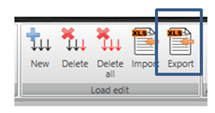
La nuova funzione può essere utilizzata per copiare le combinazioni di carico tra elementi del progetto o tra progetti diversi.
Sezioni trasversali
È stato aggiunto un ulteriore tipo di sezione trasversale. Profilo angolare con la possibilità di definire l'angolo. Può essere applicato come elemento di irrigidimento e utilizzato per la modellazione di piastre piegate.

Interfaccia utente semplificata
Finestra di dialogo di configurazione
2 finestre di dialogo di configurazione sono state unificate in una sola; sono disponibili solo i valori più importanti.

La configurazione FEA è stata rimossa, i colori sono stati spostati nelle Preferenze, ora è disponibile una sola finestra di dialogo di configurazione.
La finestra di dialogo di configurazione originale è stata riorganizzata e sono state aggiunte alcune proprietà dalla configurazione FEA.

Risultati FE
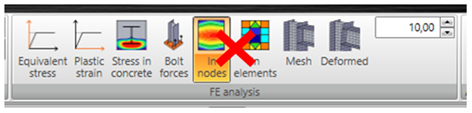
Le impostazioni "Nei nodi / Negli elementi" sono state rimosse. IDEA StatiCa Connection utilizza "negli elementi" per tutti gli output CBFEM di verifica normativa e "nei nodi" per i risultati FE di tensione e deformazione.
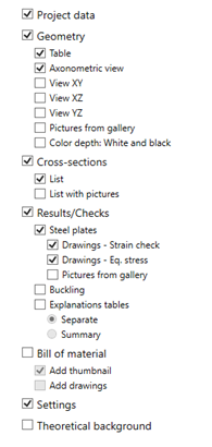
Impostazioni del report
La finestra di dialogo di configurazione, piuttosto complessa, per il report dettagliato è ora più sintetica. Abbiamo definito il contenuto obbligatorio del report e l'utente può intervenire solo su un numero limitato di opzioni.