Presentation of results
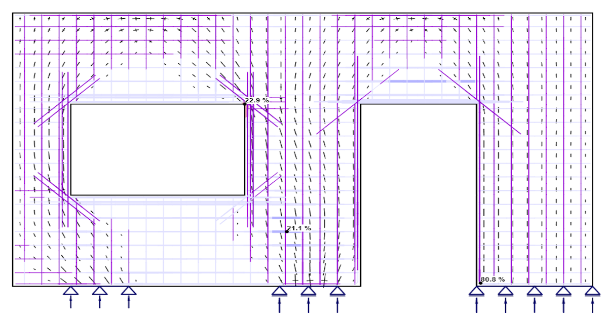
Results are presented independently for concrete and for reinforcement elements. The stress and strain values in concrete are calculated at the integration points of shell elements. However, as it is not practical to present the data in such a manner, the results are presented by default in nodes, like the maximal value of compressive stress from adjacent gauss integration points in connected elements (Fig. 18). It should be noted that this representation might locally underestimate the results at compressed edges of members in a case that the finite-element size is similar to the depth of the compression zone.
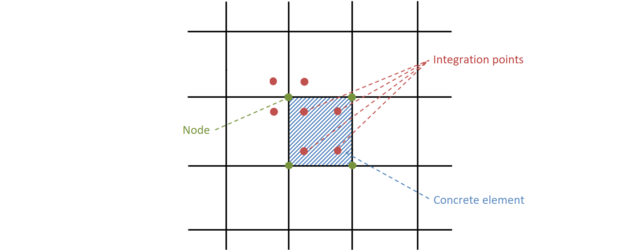
Fig. 18 - Concrete finite element with integration points and nodes: presentation of the results for concrete in nodes and in finite elements.
The results for the reinforcement finite elements are either constant for each element (one value – e.g., for steel stresses) or linear (two values – for bond results). For auxiliary elements, such as elements of bearing plates, only deformations are presented.