Rectangular hollow sections
Description
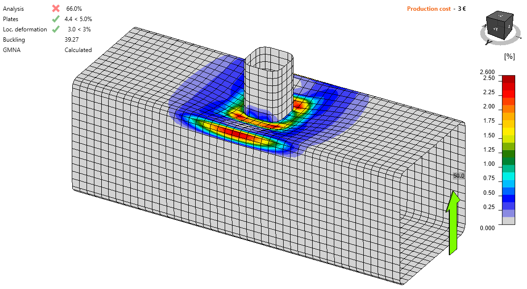
In this chapter, uniplanar welded rectangular, square, hollow sections T, X, and K-joints with gap predicted by CBFEM are verified. Square hollow sections (SHS) brace is welded directly onto an RHS chord without the use of reinforcing plates. The joints are loaded by an axial force. In CBFEM, the design resistance is limited by 5 % of strain or a force corresponding to 0,03b0 joint deformation and in FMM generally by plate out of plane deformation 0,03b0 where b0 is the depth of the RHS chord; see Lu et al. (1994).
Failure mode method
In the case of the axially loaded T, Y, X or K-joint with gap of the welded rectangular hollow sections, five failure modes can occur. These are chord face failure, chord plastification, chord side wall failure, chord web failure, chord shear failure, punching shear failure, and brace failure. In this study, chord face failure, brace failure, and punching shear failure are examined for T, Y and X-joint and chord face failure, chord shear failure, brace failure, and punching shear failure are examined for K-joint with gap; see Fig. 7.2.1. The welds designed according to EN 1993-1-8:2005 are not the weakest components in the joint.

\[ \textsf{\textit{\footnotesize{Fig. 7.2.1 Examined failure modes: a) Chord face failure, b) Chord shear failure, c) Brace failure, and d) Punching shear failure}}}\]
Chord face failure
The design resistance of an RHS chord face is determined by FMM model in section 9.5 of EN 1993‑1-8:2020. The method is also given in the ISO/FDIS 14346 and is described in detail in Wardenier et al. (2010). The design resistance of the axially loaded T, Y or X-joint of welded rectangular hollow sections is
\[ N_{i,Rd} = C_f \frac{f_{y0} t_0^2}{\sin{\theta_i}} \left ( \frac{2 \eta}{(1-\beta) \sin{\theta_i}} + \frac{4}{\sqrt{1-\beta}} \right ) Q_f / \gamma_{M5} \]
The design resistance of the axially loaded K-joint with gap of welded rectangular hollow sections is
\[ N_{i,Rd} = 8.9 C_f \beta \gamma^{0.5} \frac{f_{y,0} t_0^2}{\sin{\theta_i}} Q_f / \gamma_{M5} \]
where Cf is the material factor, fy0 is the yield stress of the chord, t0 is the wall thickness of the chord, η is the brace height to the chord width ratio, β is the brace width to the chord width ratio, qi is the included angle between the brace member i and the chord (i = 1, 2), Qf is the chord stress function, and γ is the chord slenderness ratio.
Brace failure
The design resistance of an RHS chord face can be determined using the method given by FMM model in section 9.5 of EN 1993-1-8:2020. The design resistance of the axially loaded T, Y or X-joint of welded rectangular hollow sections is
\[ N_{i,Rd} = C_f f_{yi} t_i (2 h_i - 4 t_i + 2 b_{eff} ) / \gamma_{M5} \]
The design resistance of the axially loaded K-joint with gap of welded rectangular hollow sections is
\[ N_{i,Rd} = C_f f_{yi} t_i (2 h_i - 4 t_i + b_i + b_{eff} ) / \gamma_{M5} \]
where Cf is the material factor, fyi is the yield stress of the brace member i (i = 1, 2), ti is the wall thickness of the brace member i, hi is the height of the brace member i, bi is the width of the brace member i, beff is the effective width of the brace member.
Punching shear
The design resistance of the axially loaded T, Y or X-joint of welded rectangular hollow sections is
\[ N_{i,Rd} = C_f \frac{f_{y0} t_0}{\sqrt{3}\sin{\theta_i}} \left( \frac{2h_i}{\sin{\theta_i}} + 2b_{e,p} \right ) / \gamma_{M5} \]
The design resistance of the axially loaded K-joint with gap of welded rectangular hollow sections is
\[ N_{i,Rd} = C_f \frac{f_{y0} t_0}{\sqrt{3}\sin{\theta_i}} \left( \frac{2h_i}{\sin{\theta_i}} + b_i+b_{e,p} \right ) / \gamma_{M5} \]
Where Cf is the material factor, fy0 is the yield stress of the chord, t0 is the wall thickness of the chord, qi is the included angle between the brace member i and the chord (i = 1, 2), hi is the height of the brace member i, bi is the width of the brace member i and be,p is the effective width for punching shear.
Chord shear failure
The design resistance of the axially loaded K-joint with gap of welded rectangular hollow sections is
\[ N_{i,Rd} = \frac{f_{y0}A_{V,0,gap}}{\sqrt{3}\sin{\theta_i}}/\gamma_{M5} \]
where fy0 is the yield stress of the chord, Av,0,gap is the effective area for chord shear failure, and qi is the included angle between the brace member i and the chord (i = 1, 2).
Range of validity
CBFEM was verified for typical T, Y X, and K-joints with gap of the welded rectangular hollow sections. Range of validity for these joints is defined in Table 9.2 of prEN 1993-1-8:2020; see Tab. 7.2.1. The same range of validity is applied to CBFEM model. Outside the range of validity of FMM, an experiment should be prepared for validation or verification performed for verification according to a validated research model.
Tab. 7.2.1 Range of validity for method of failure modes, Table 9.2 of EN 1993-1-8:2020
| General | \(0.2 \le \frac{d_i}{d_0} \le 1.0 \) | \( \theta_i \ge 30^{\circ} \) | \(\frac{e}{d_0} \le 0.25 \) |
| \(g \ge t_1+t_2 \) | \(f_{yi} \le f_{y0} \) | \( t_i \le t_0 \) |
| Chord | Compression | Class 1 or 2 and \( d_0 / t_0 \le 50 \) (but for X joints: \( d_0/t_0 \le 40 \)) |
| Tension | \(d_0 / t_0 \le 50 \) (but for X joints: \( d_0/t_0 \le 40 \)) | |
| CHS braces | Compression | Class 1 or 2 and \(b_i / t_i \le 35\) and \(\frac{h_i}{t_i} \le 35 \) |
| Tension | \(b_i / t_i \le 35\) and \(\frac{h_i}{t_i} \le 35 \) |
7.2.2 Uniplanar T and Y-SHS joint
An overview of the considered examples is given in Tab. 7.2.2. Selected cases cover a wide range of joint geometric ratios. Geometry of joints with dimensions is shown in Fig. 7.2.2. Selected joints failed according to the method based on FMM by the chord face failure or brace failure.
Tab. 7.2.2 Examples overview
| Example | Chord | Brace | Angles | Material | ||
| Section | Section | θ1 | fy | fu | E | |
| [°] | [MPa] | [MPa] | [MPa] | |||
| 1 | SHS200/6.3 | SHS90/8.0 | 90 | 355 | 490 | 210 |
| 2 | SHS200/8.0 | SHS90/8.0 | 90 | 355 | 490 | 210 |
| 3 | SHS200/12.5 | SHS120/12.5 | 90 | 355 | 490 | 210 |
| 4 | SHS200/6.3 | SHS140/12.5 | 60 | 355 | 490 | 210 |
| 5 | SHS200/8.0 | SHS80/8.0 | 60 | 355 | 490 | 210 |
| 6 | SHS200/10.0 | SHS120/12.5 | 60 | 355 | 490 | 210 |
| 7 | SHS200/12.5 | SHS90/8.0 | 60 | 355 | 490 | 210 |
| 8 | SHS200/6.3 | SHS100/10.0 | 30 | 355 | 490 | 210 |
| 9 | SHS200/8.0 | SHS150/16.0 | 30 | 355 | 490 | 210 |
| 10 | SHS200/10.0 | SHS100/10.0 | 30 | 355 | 490 | 210 |
| 11 | SHS200/12.5 | SHS100/10.0 | 30 | 355 | 490 | 210 |

\[ \textsf{\textit{\footnotesize{Fig. 7.2.2 Dimensions of T-joint}}}\]
Verification of resistance
The results of FMM are compared with the results of CBFEM. The comparison is focused on the resistance and design failure mode. The results are presented in Tab. 7.2.3.
Tab. 7.2.3 Comparison of results of design resistances in tension/compression predicted by CBFEM and FMM
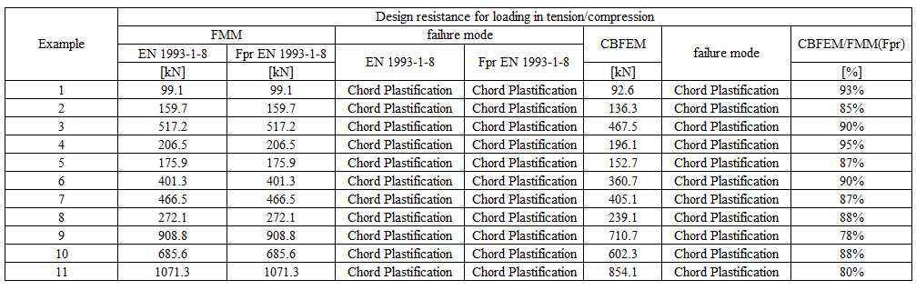
The study shows a good agreement for the applied load cases. The results are summarized in a diagram comparing design resistances of CBFEM and FMM; see Fig. 7.2.3. The results show that the difference between the two calculation methods is in all cases less than 10 %.
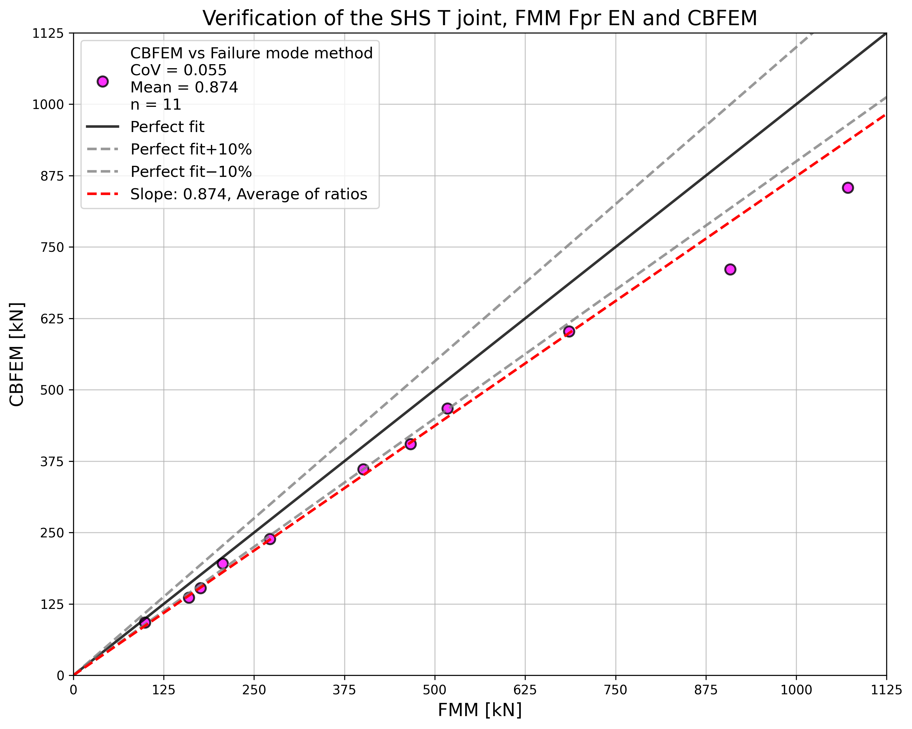
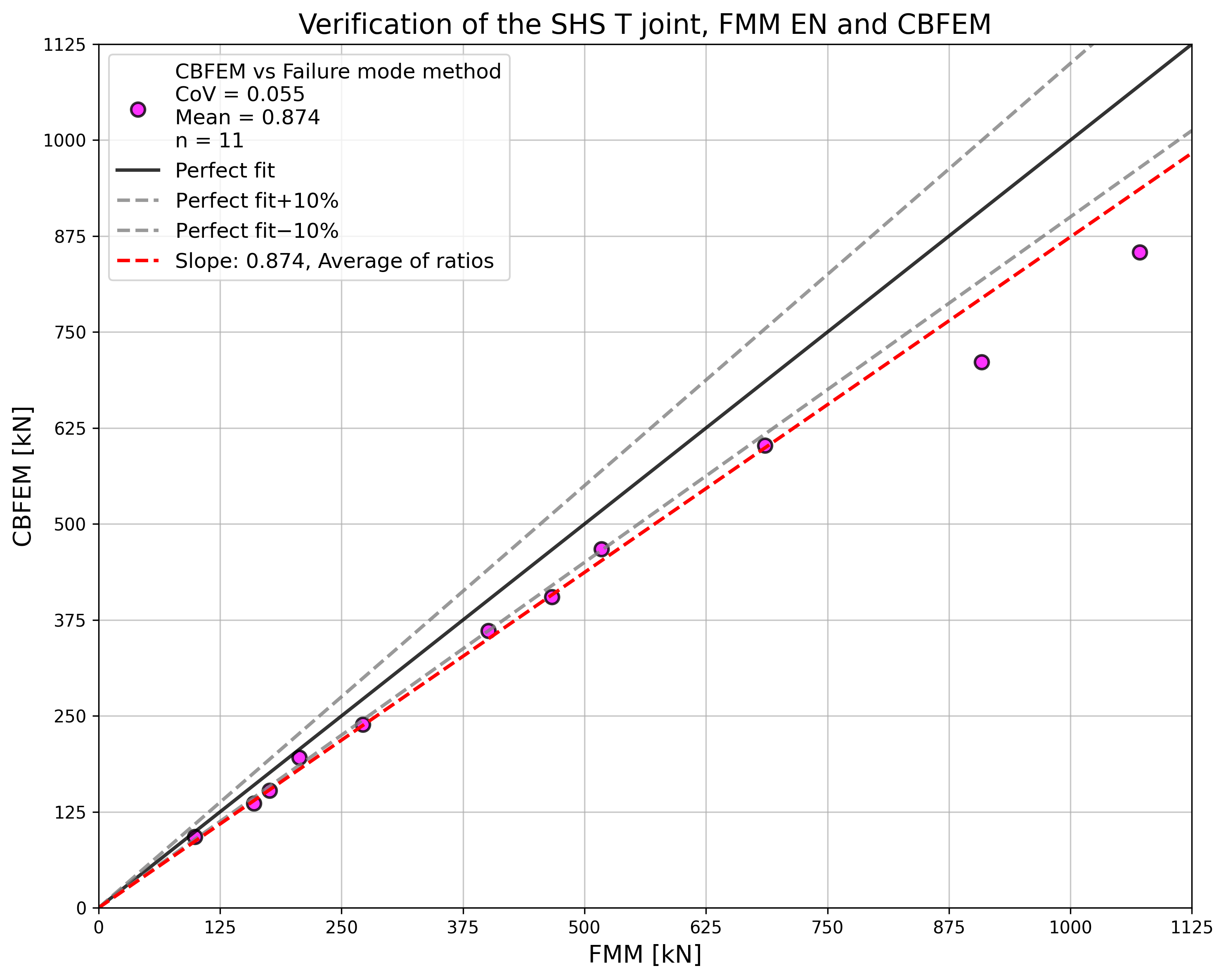
\[ \textsf{\textit{\footnotesize{Fig. 7.2.3 Verification of resistance determined by CBFEM to FMM for the uniplanar SHS T and Y-joint}}}\]
Benchmark example
Inputs
Chord
- Steel S355
- Section SHS 200×200×6.3
Brace
- Steel S355
- Section SHS 90×90×8.0
- Angle between the brace member and the chord 90°
Weld
- Butt weld
Mesh size
- 16 elements on the biggest web of rectangular hollow member
Loaded
- By force to brace in compression/tension
Outputs
- The design resistance in compression/tension is NRd = 92.6 kN
- The design failure mode is chord face failure
Uniplanar X-SHS joint
An overview of the considered examples is given in Tab. 7.2.4. Selected cases cover a wide range of joint geometric ratios. The selected joints failed according to the method based on FMM by the chord face failure or brace failure.
Tab. 7.2.4 Examples overview
| Example | Chord | Brace | Angles | Material | ||
| Section | Section | θ | fy | fu | E | |
| [°] | [MPa] | [MPa] | [MPa] | |||
| 1 | SHS200/6.3 | SHS140/12.5 | 90 | 355 | 490 | 210 |
| 2 | SHS200/8.0 | SHS70/8.0 | 90 | 355 | 490 | 210 |
| 3 | SHS200/10.0 | SHS120/12.5 | 90 | 355 | 490 | 210 |
| 4 | SHS200/12.5 | SHS90/8.0 | 90 | 355 | 490 | 210 |
| 5 | SHS200/6.3 | SHS90/8.0 | 60 | 355 | 490 | 210 |
| 6 | SHS200/8.0 | SHS80/8.0 | 60 | 355 | 490 | 210 |
| 7 | SHS200/10.0 | SHS150/6.3 | 60 | 355 | 490 | 210 |
| 8 | SHS200/12.5 | SHS140/12.5 | 60 | 355 | 490 | 210 |
| 9 | SHS200/16.0 | SHS120/12.5 | 60 | 355 | 490 | 210 |
| 10 | SHS200/6.3 | SHS100/8.0 | 30 | 355 | 490 | 210 |
| 11 | SHS200/8.0 | SHS150/16.0 | 30 | 355 | 490 | 210 |
| 12 | SHS200/10.0 | SHS100/10.0 | 30 | 355 | 490 | 210 |
| 13 | SHS200/16.0 | SHS90/8.0 | 30 | 355 | 490 | 210 |
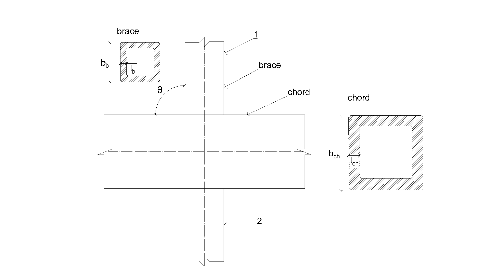
\[ \textsf{\textit{\footnotesize{Fig. 7.2.4 Dimensions of X-joint}}}\]
Verification of resistance
The results of the method based on failure modes (FMM) are compared with the results of CBFEM. The comparison is focused on the resistance and design failure mode; see Tab. 7.2.5.
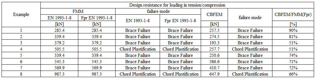
Tab. 7.2.5 Comparison of results of prediction of resistance by CBFEM and FMM

The study shows a good agreement for the applied load cases. The results are summarized in a diagram comparing design resistances of CBFEM and FMM; see Fig. 7.2.4. The results show that the difference between the two calculation methods is in all cases less than 13 %.
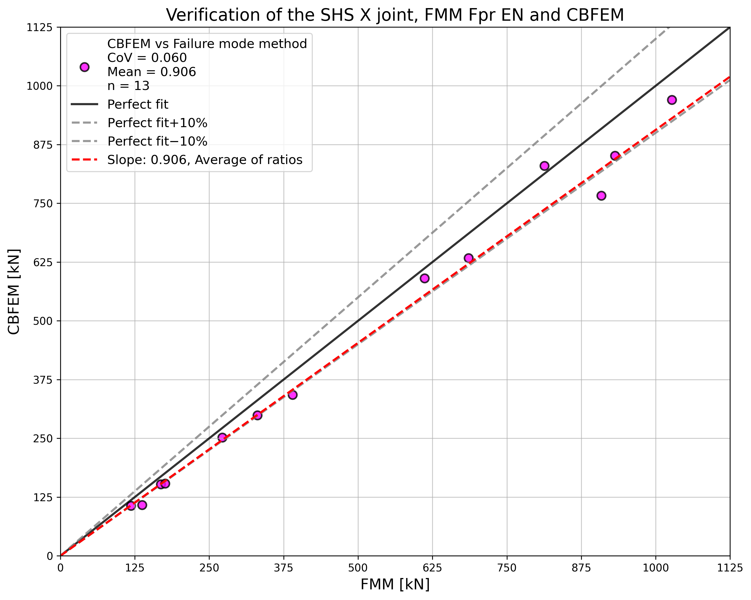

\[ \textsf{\textit{\footnotesize{Fig. 7.2.5 Verification of resistance determined by CBFEM to FMM for the uniplanar SHS X-joint}}}\]
Benchmark example
Inputs
Chord
- Steel S355
- Section SHS 200×200×6,3
Braces
- Steel S355
- Sections SHS 140×140×12,5
- Angle between the brace members and the chord 90°
Welds
- Butt welds
Mesh size
- 16 elements on the biggest web of rectangular hollow member
Loaded
- By force to brace in compression/tension
Outputs
- The design resistance in compression/tension is NRd = 152.4 kN
- The design failure mode is chord face failure
7.2.4 Uniplanar K-SHS joint
An overview of the considered examples is given in Tab. 7.2.6. Selected cases cover a wide range of joint geometric ratios. The selected joints failed according to the method based on FMM by the chord face failure or brace failure.
Tab. 7.2.6 Examples overview
| Example | Chord | Braces | Angles | Material | ||
| Section | Sections | θ | fy | fu | E | |
| [°] | [MPa] | [MPa] | [MPa] | |||
| 1 | SHS180/10.0 | SHS70/3.0 | 45 | 355 | 490 | 210 |
| 2 | SHS180/10.0 | SHS70/3.6 | 45 | 355 | 490 | 210 |
| 3 | SHS200/8.0 | SHS80/3.6 | 45 | 355 | 490 | 210 |
| 4 | SHS200/8.0 | SHS100/10.0 | 45 | 355 | 490 | 210 |
| 5 | SHS200/200/10.0 | SHS70/3.6 | 45 | 355 | 490 | 210 |
| 6 | SHS200/200/10.0 | SHS100/4.0 | 45 | 355 | 490 | 210 |
| 7 | SHS200/200/12.5 | SHS70/6.3 | 45 | 355 | 490 | 210 |
| 8 | SHS200/200/12.5 | SHS100/8.0 | 45 | 355 | 490 | 210 |
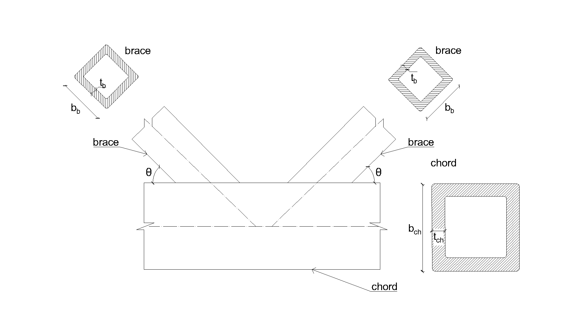
\[ \textsf{\textit{\footnotesize{Fig. 7.2.6 Dimensions of K-joint}}}\]
Verification
The results of CBFEM are compared with the results of FMM. The comparison is focused on the resistance and design failure mode. The results are presented in Tab. 7.2.7.
Tab. 7.2.7 Comparison of results of prediction of resistances by CBFEM and FMM
The study shows a good agreement for the applied load cases. The results are summarized in a diagram comparing design resistances of CBFEM and FMM; see Fig. 7.2.5. The results show that the difference between the two calculation methods is in all cases less than 10%.
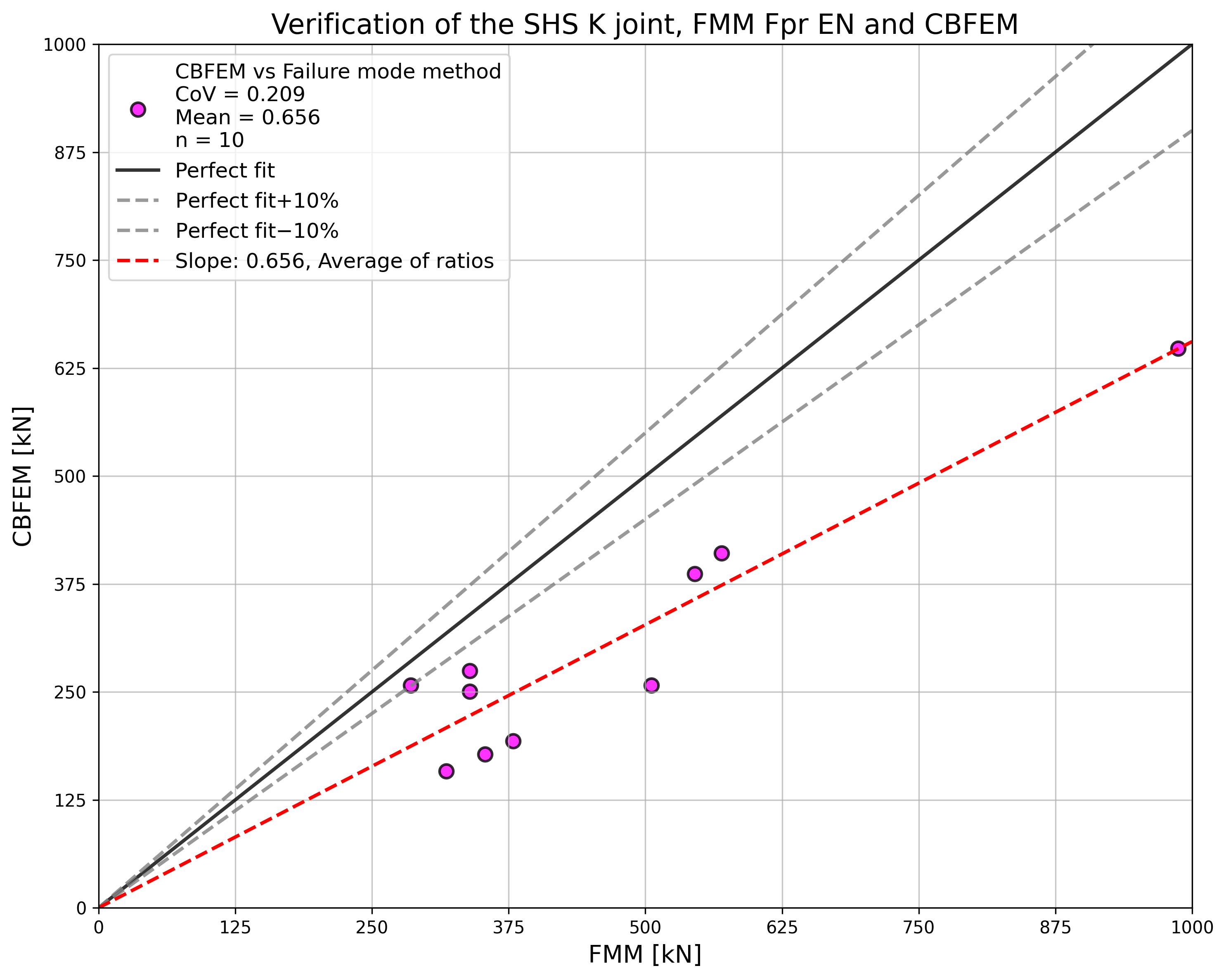
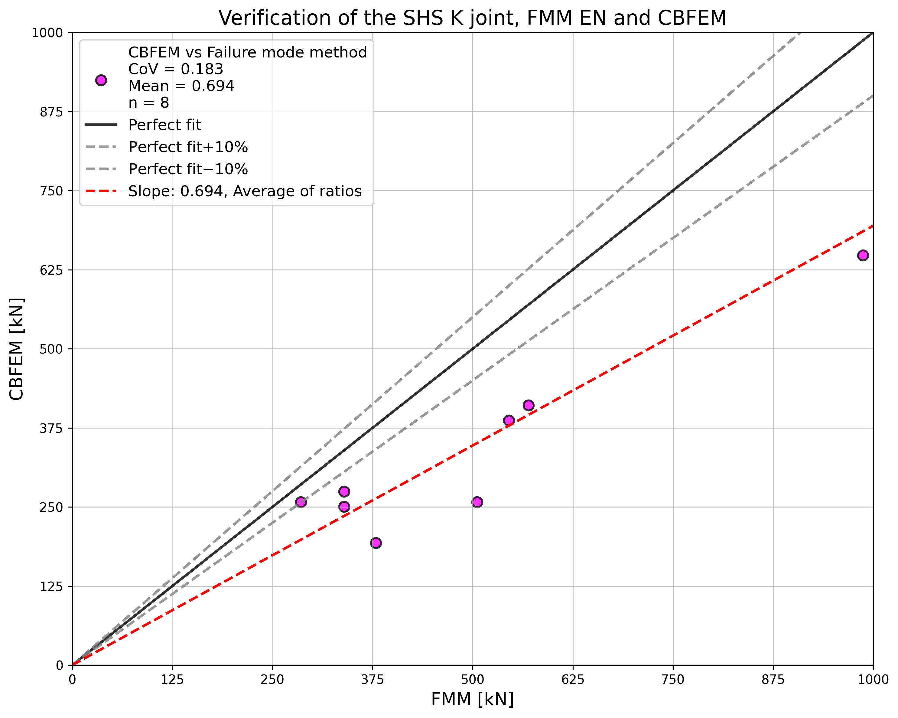
\[ \Fig. 7.2.7 Verification of resistance determined by CBFEM to FMM for the uniplanar SHS K-joint}}}\]
Benchmark example
Inputs
Chord
- Steel S355
- Section SHS 180×180×10,0
Braces
- Steel S355
- Sections SHS 70×70×3,0
- Angle between the brace members and the chord 45°
Welds
- Butt welds
Mesh size
- 16 elements on the biggest web of rectangular hollow member
Loaded
- By force to brace in compression/tension
Outputs
- The design resistance in compression/tension is NRd = 257.5 kN
- The design failure mode is chord face failure