Advance Steel BIM link acél kapcsolat tervezéséhez (EN)
Hogyan aktiváljuk a linket
- Töltse le és telepítse az IDEA StatiCa legújabb verzióját
- Győződjön meg arról, hogy az FEA szoftver támogatott verzióját használja
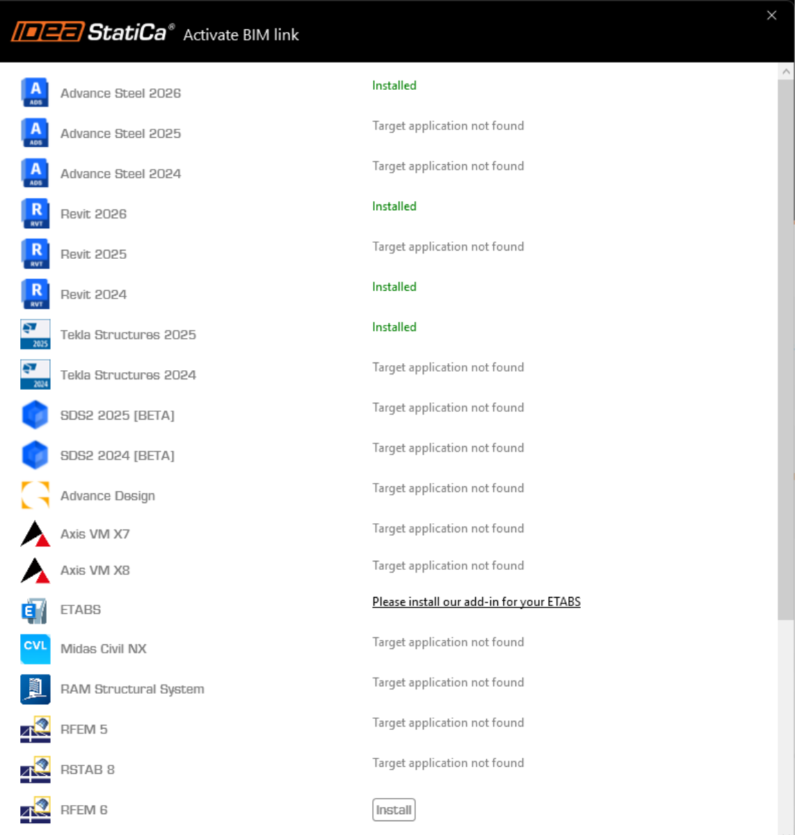
Az IDEA StatiCa a telepítés során integrálja a BIM linkeket az FEA szoftverébe. A státuszt ellenőrizheti, és szükség esetén további BIM linkeket integrálhat az IDEA StatiCa futtatásával és a BIM linkek megnyitásával. Kérjük, vegye figyelembe, hogy egyes FEA szoftverek további lépéseket igényelnek a BIM link teljes aktiválásához az IDEA StatiCa felé.
Megjelenhet egy „Engedélyezi, hogy ez az alkalmazás módosításokat végezzen az eszközén?" értesítés, ha igen, kérjük, erősítse meg az Igen gombbal.
A Telepítés gombra kattintva a kiválasztott szoftver BIM linkje integrálódik. A képernyő a többi BIM link státuszát is megjeleníti.
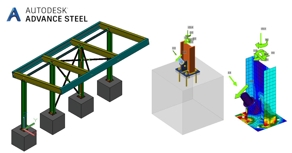
Töltse le a csatolt projektet és nyissa meg az Advance Steel-ben.
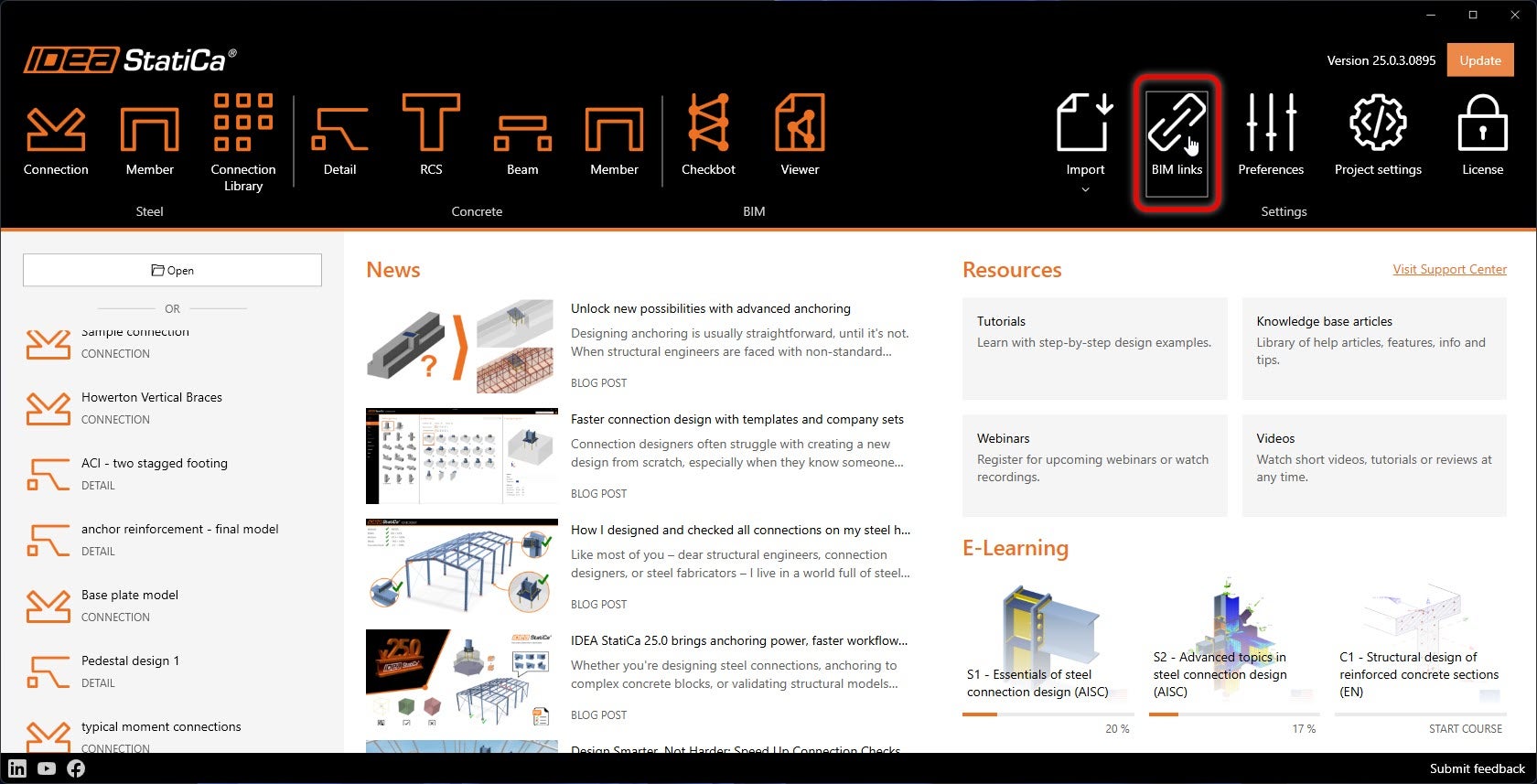
A BIM link automatikusan integrálva van. A felső szalagmenüben találja az IDEA StatiCa -> Checkbot menüpont alatt. Ez megnyitja a Checkbot alkalmazást.

Válassza az Új lehetőséget, a projekt típusaként válassza az Acél, a tervezési szabványként az EN opciót. Ezután válassza a Projekt létrehozása lehetőséget.
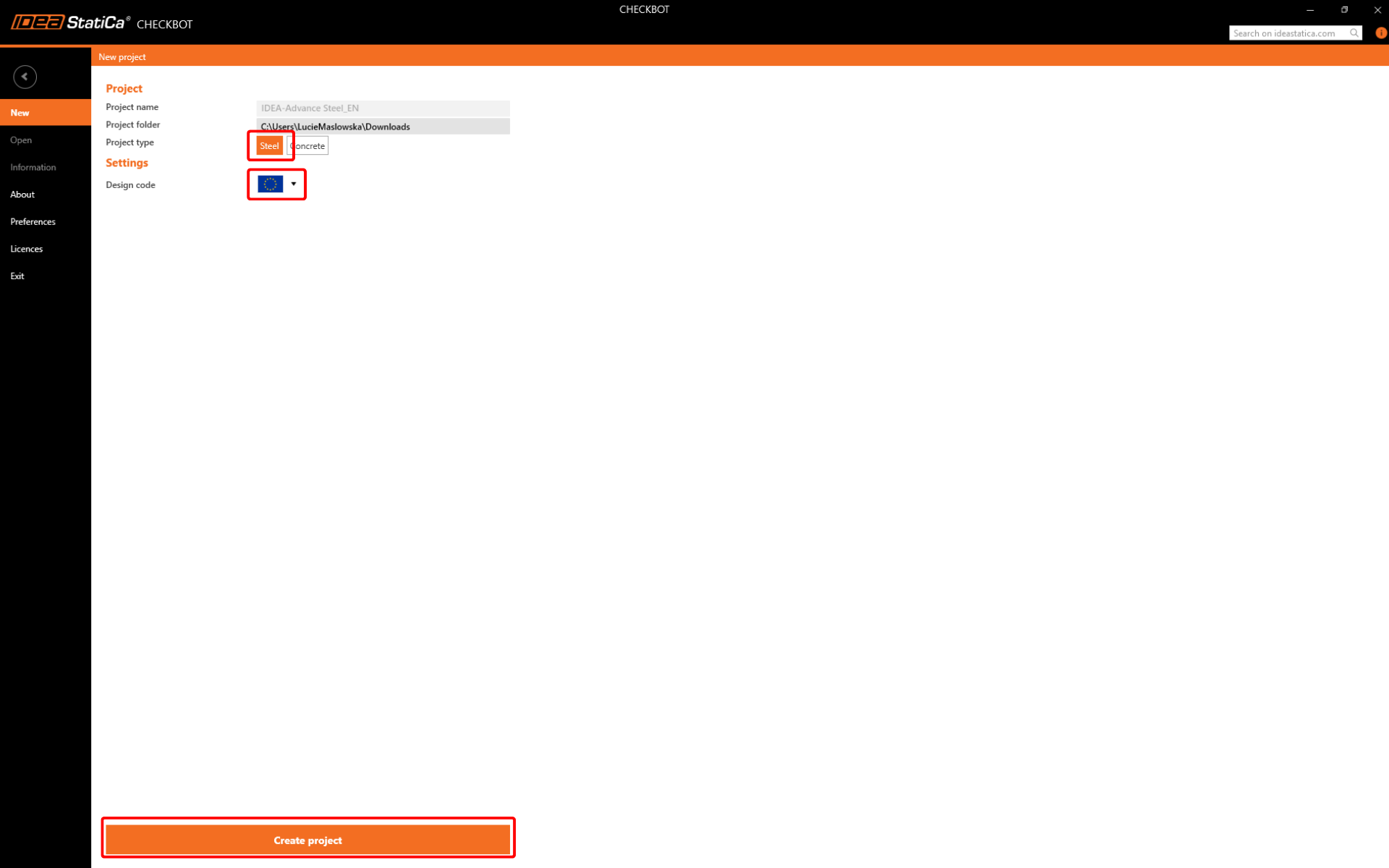
Az új Checkbot projekt készen áll a kapcsolatok importálására az Advance Steel-ből.
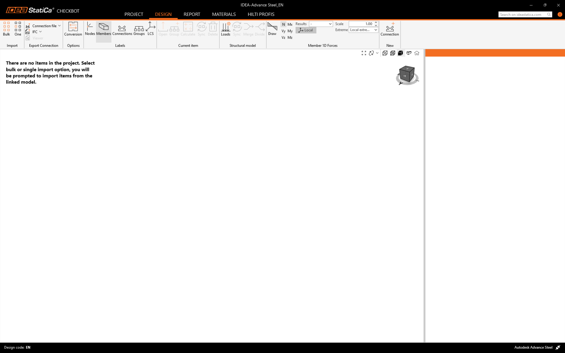
Importálás
A modell Checkbot-ba való importálásának két lehetősége van:
I. A szerkezet nagyobb részének Checkbot-ba való importálásához válassza a Bulk lehetőséget. (Ebben az oktatóanyagban ezt használjuk.)

Ez a szerkezet összes kiválasztott részét importálja a Checkbot-ba – ugyanolyan koordinátákkal, tájolásokkal és keresztmetszet-méretekkel, mint a BIM modellben. A csomópont középpontját a szoftver automatikusan hozza létre az elemek metszéspontja szerint. Javasoljuk, hogy ne importálja az összes kapcsolatot egyszerre, hanem fokozatosan építse fel azokat.
II. Alternatívaként egyetlen csomópontot is exportálhat a Checkbot felső szalagjában található One gomb segítségével.
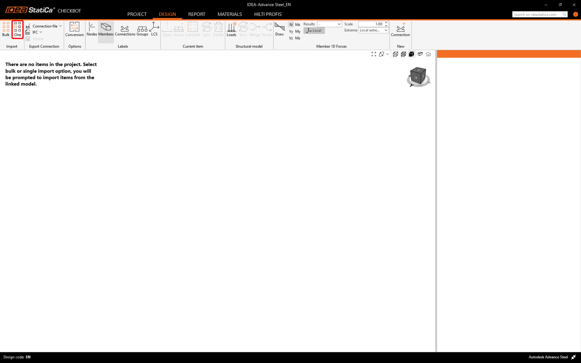
Szüntessen meg minden kijelölést a BIM modell szerkezetében, majd nyomja meg az One gombot. Ezután:
- A BIM modellben válassza ki a csomópontot, amely a kapcsolat középpontját jelöli, és erősítse meg a szóközzel, a jobb egérgombbal vagy az Enter billentyűvel.
- Most válassza ki a szerkezeti elemeket, például gerendákat és oszlopokat. A kiválasztott elemek sorrendje határozza meg az elemek sorrendjét a Connection modellben. Erősítse meg az 1. lépéshez hasonlóan.
- Válassza ki az összes többi kapcsolati elemet, például csavarokat, lemezeket stb., majd erősítse meg újra.
A kapcsolat most átkerül a Checkbot-ba.
Válasszon a két importálási mód (Bulk vagy One) között. Mindkettő sikeresen importálja a szerkezetet.
Az Advance Steel-ben válasszon ki egy belső oszlopot merevítőkkel együtt, ügyelve arra, hogy az összes kapcsolati objektumot is kiválassza.

Kérjük, vegye figyelembe, hogy a csomópont- és elemszámozás eltérő lehet.
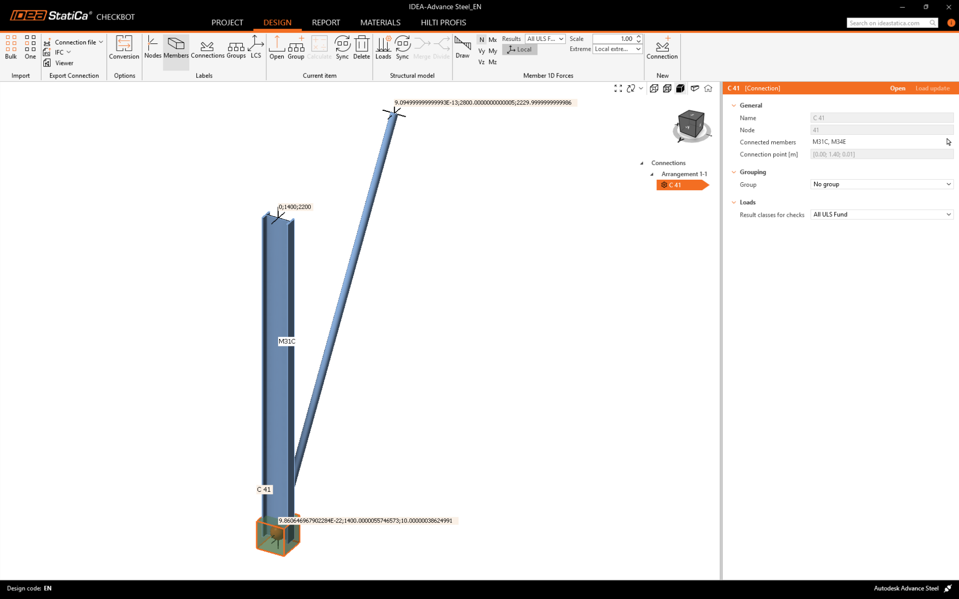
Kérjük, vegye figyelembe, hogy a 3D munkaterület az importált szerkezet áttekintésének megjelenítésére szolgál, nem pedig a tényleges kapcsolatok részletes nézetére. A Checkbot-tal kapcsolatos további információkért lásd itt.
Geometria
A projekt elemeinek listájában a Kapcsolatok alatt, egy kiemelt kapcsolattal a Checkbot-ban, jobb egérgombbal kattinthat és kiválaszthatja a Megnyitás lehetőséget, vagy kattinthat a szalag Megnyitás parancsára a tervezés, szabványellenőrzés és jelentéskészítés megkezdéséhez.
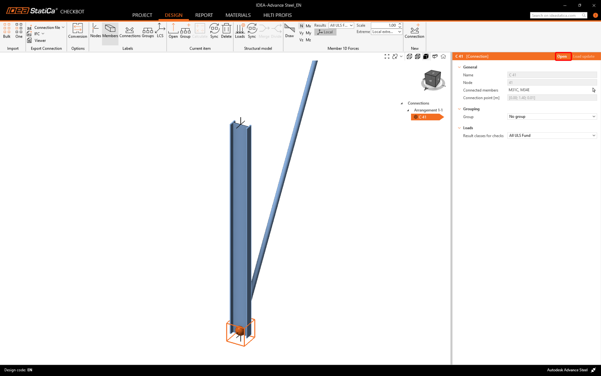
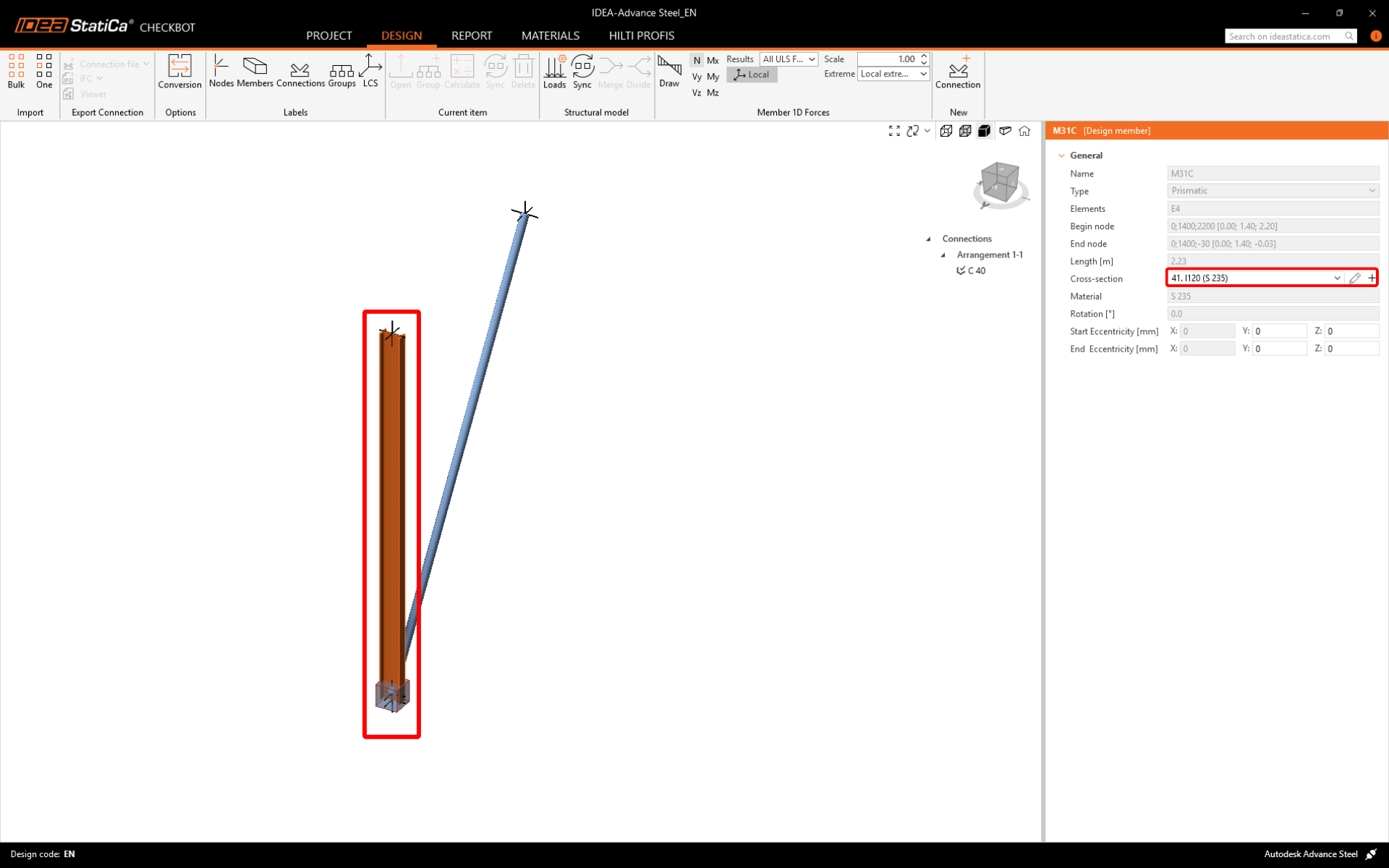
A szerkezeti elemek beállításai az eredeti BIM alkalmazásból kerülnek átvételre. Azonban megváltoztathatja bármely szerkezeti elem keresztmetszetének méretét a Checkbot főképernyőjén, de ez megszakítja a kapcsolatot a BIM alkalmazással ebben a munkamenetben, hacsak nem szinkronizálják újra.
Az importált kapcsolat az IDEA StatiCa Connection alkalmazásban nyílik meg.
Teherhatások
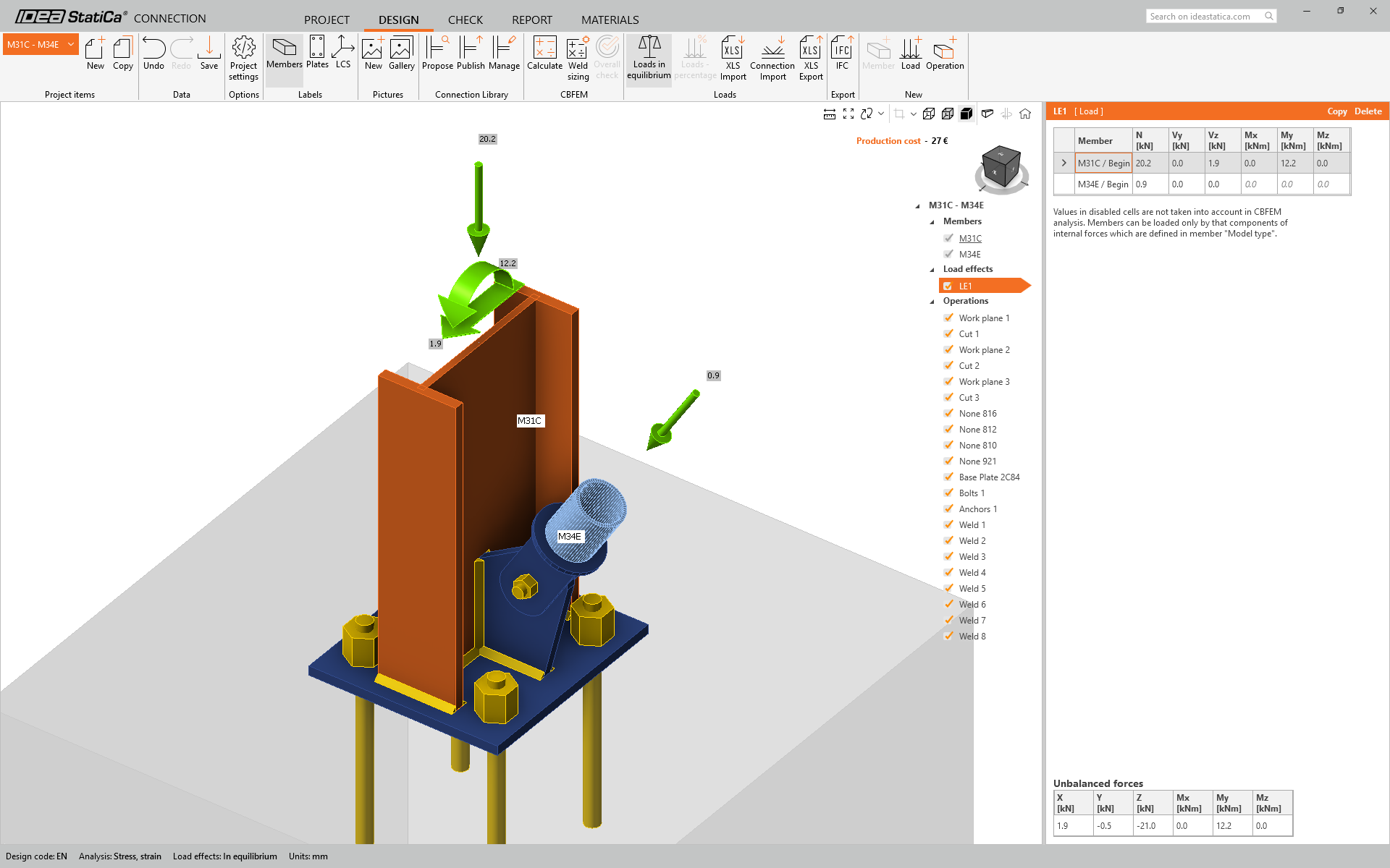
Töltse le a csatolt Excel táblázatot a teherhatásokkal, és nyissa meg.
Jelölje ki a belső erők értékeit a táblázatban, és másolja ki őket (Ctrl + C).

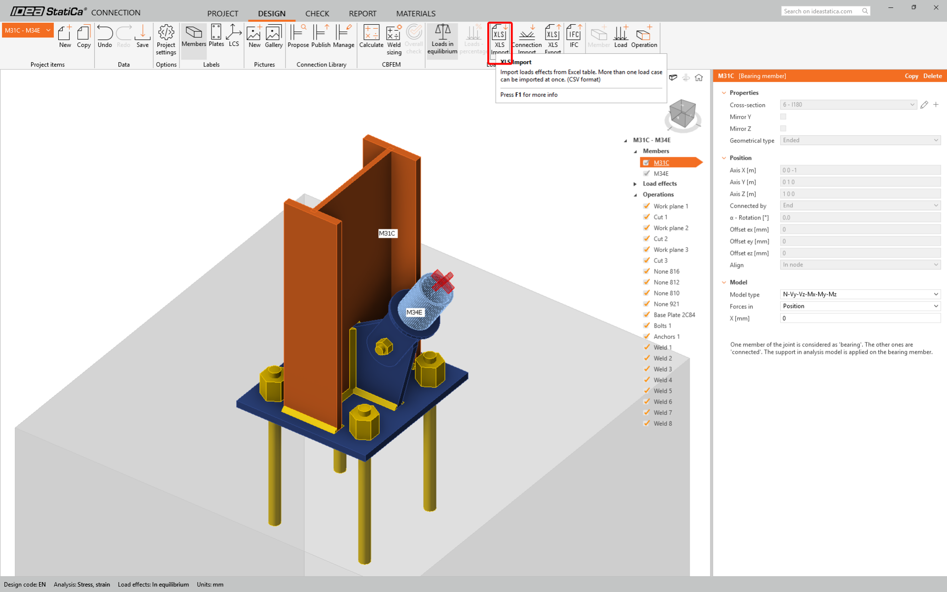
Ezután az IDEA StatiCa Connection alkalmazásban válassza az XLS Import gombot a felső szalagon.
Bal egérgombbal kattintva jelölje ki az első cellát, majd illessze be (Ctrl + V) a belső erők értékeit.
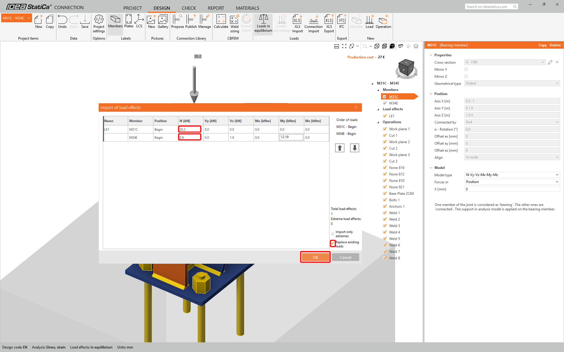
Kérjük, vegye figyelembe, hogy az Excel táblázatban a sorok és oszlopok sorrendjének meg kell egyeznie az IDEA StatiCa Connection alkalmazás Teherhatások táblázatában szereplő sorrenddel. Ha a sorok vagy oszlopok fel vannak cserélve, a szerkezeti elemekre vonatkozó belső erők helytelen bevitelét kapja.
Tervezés
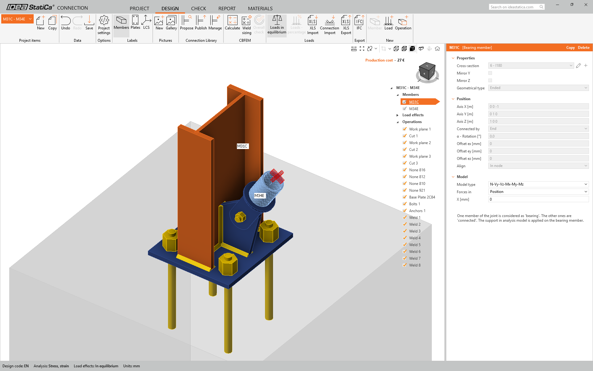
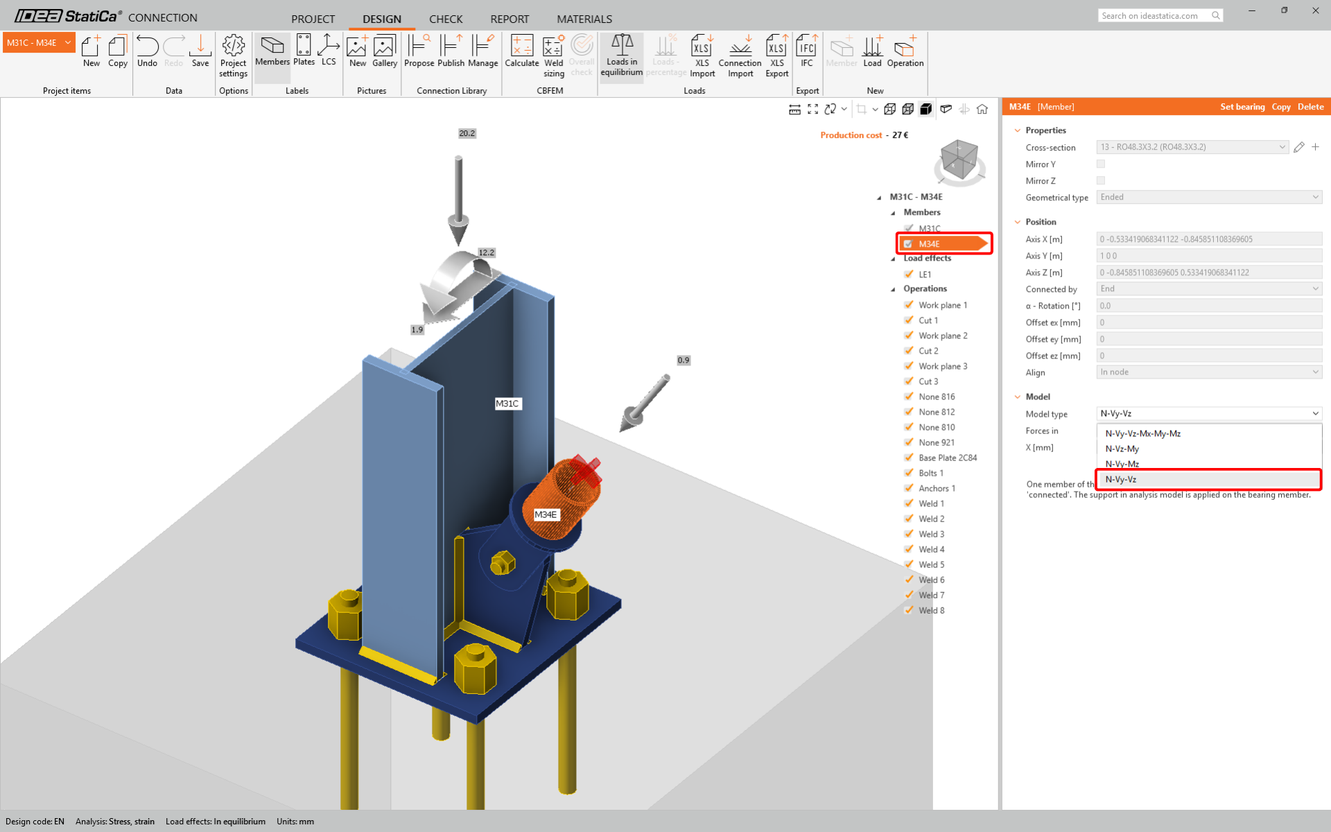
Az átlós merevítőhöz egybultos kapcsolatot fogunk használni. Ennél a kapcsolattípusnál a merevítő elem Modell típusát is módosítani kell N-Vy-Vz-re. Válassza ki a merevítőt az Elemek listájában, és módosítsa a Modell típusát a legördülő listában.
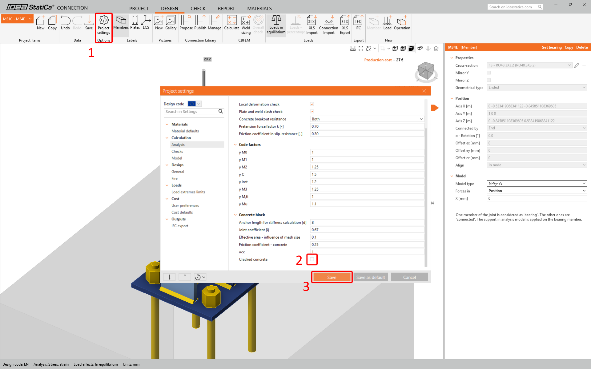
Lépjen a felső szalagon a Kódbeállítások menüpontra, és törölje a jelölést a Repedezett beton opcióból.
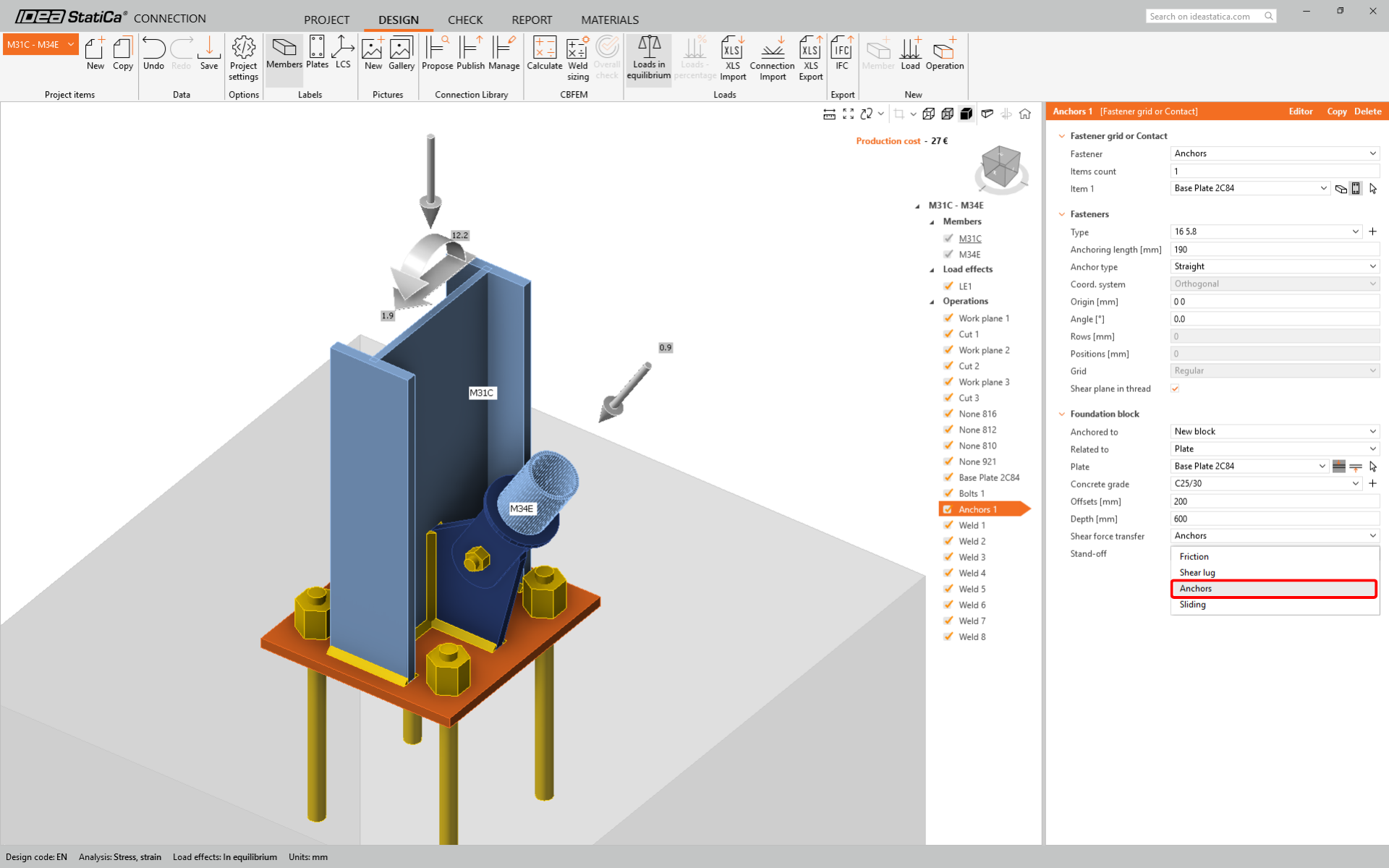
Állítsa be a horgonyok és a betonblokk tulajdonságait. Válassza a Nyírási sík a menetben opciót. Állítsa az Eltolás értékét 200 mm-re. Módosítsa a Betonosztályt C25/30-ra.
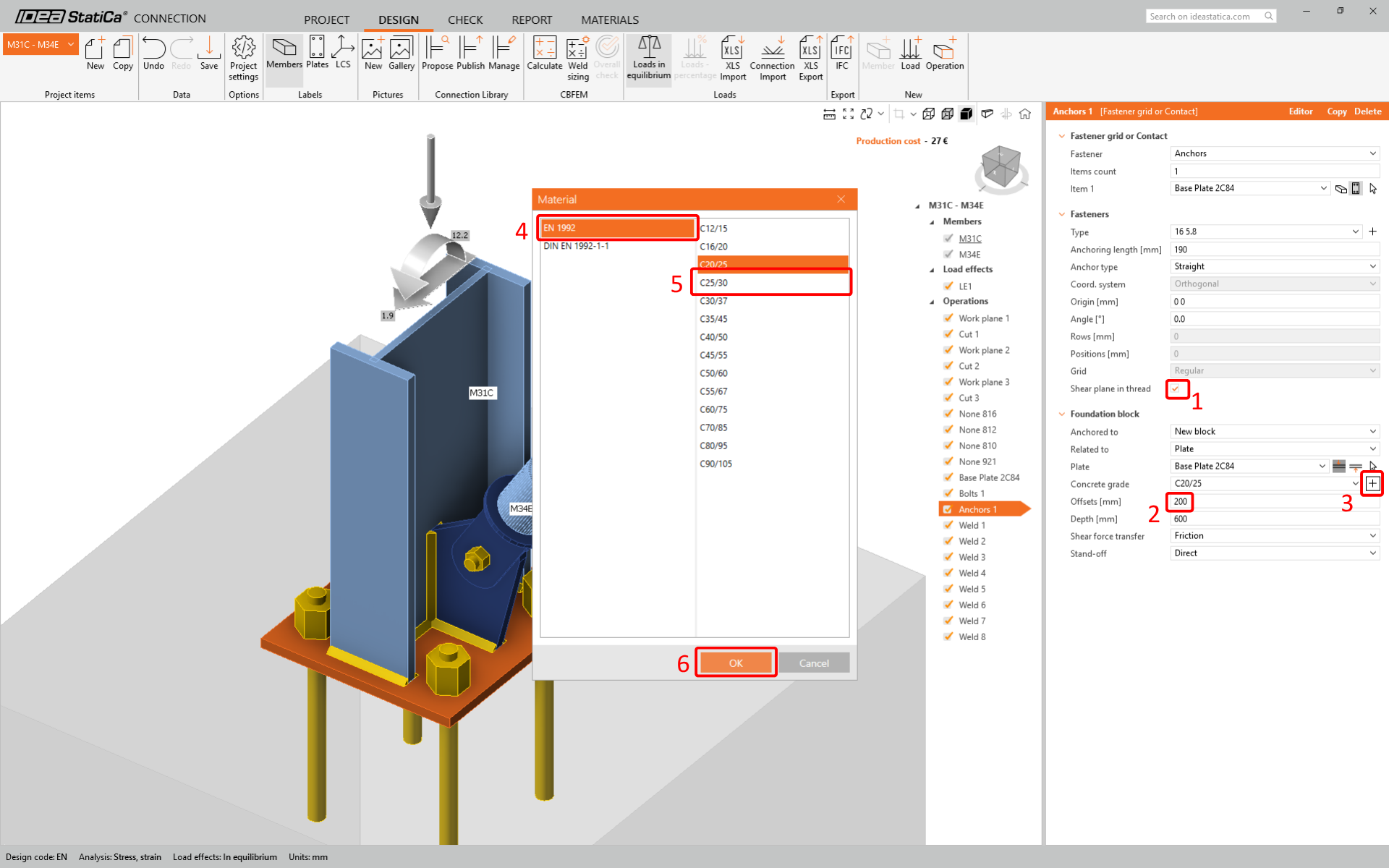
Végül válassza a Nyíróerők átadása lehetőségnél a Horgonyok opciót.
Szabványellenőrzés és Jelentés
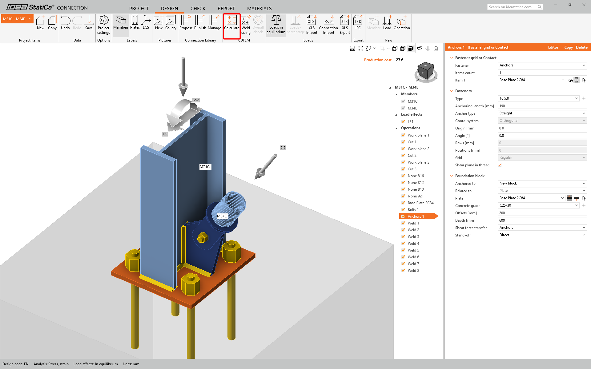
Most futtasson szabványellenőrzést a felső szalag CBFEM paneljének Számítás ikonjával.
Az IDEA StatiCa Connection számos különböző típusú analízist és szabványellenőrzést tesz lehetővé. További információkért kérjük, tekintse meg itt.
Miután a szabványellenőrzés befejeződött, a Jelentés fülön létrehozhatja a kapcsolati modell eredményeités diagramjait tartalmazó jelentést.

A jelentés kinyomtatható vagy több formátumban menthető. További információkért kérjük, tekintse meg itt.

Mentse el és lépjen ki ebből a kapcsolatból vissza a Checkbot-ba.
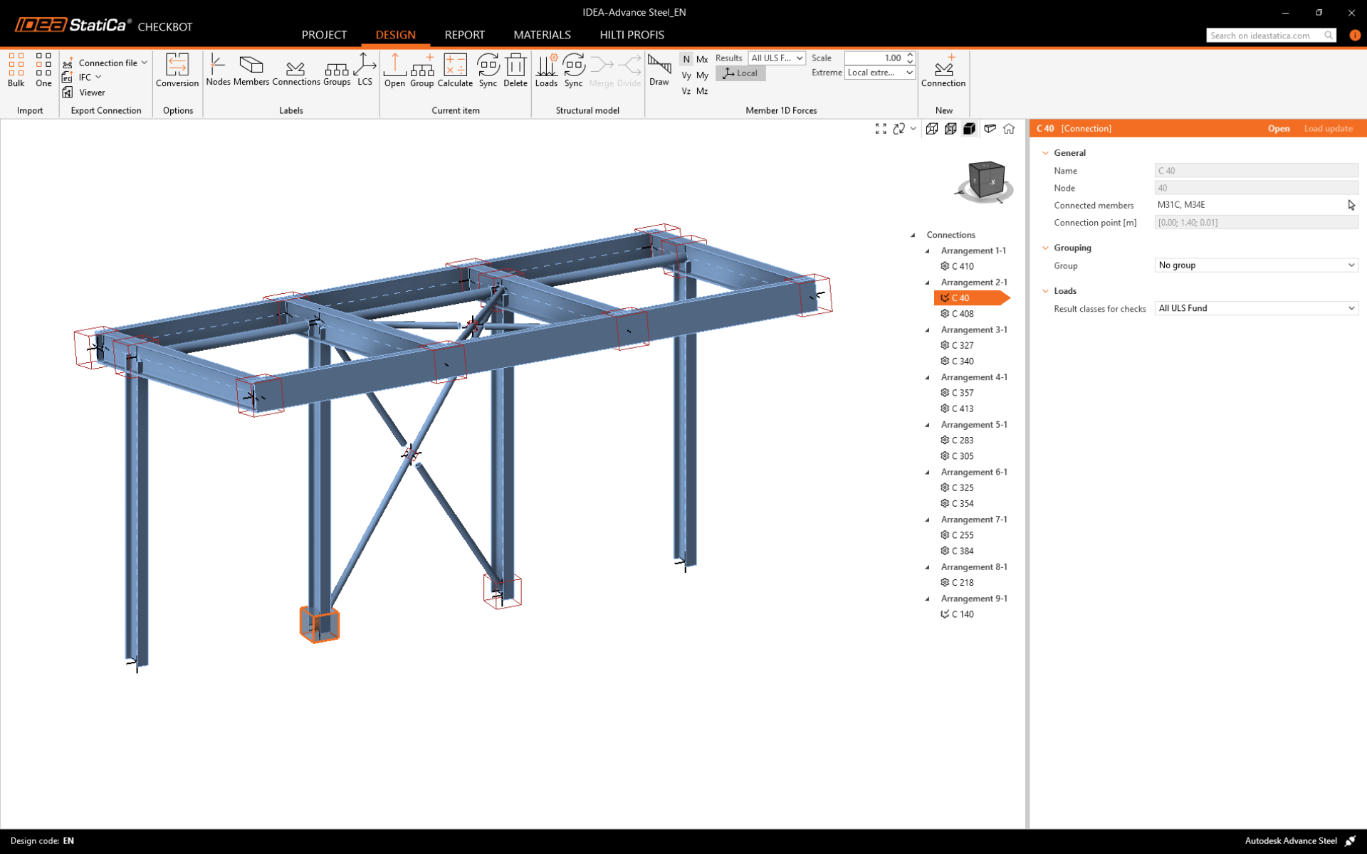
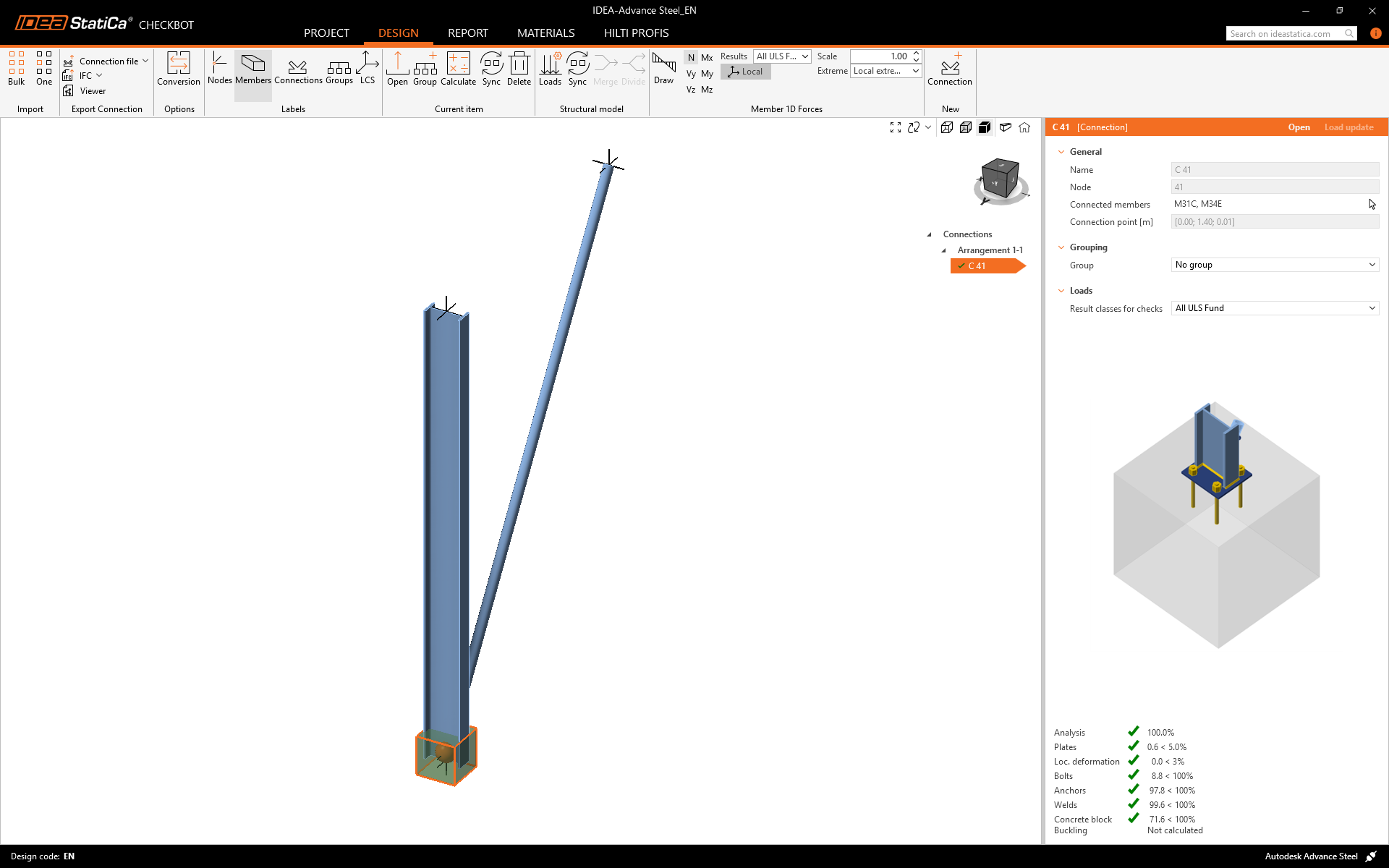
A Checkbot-ban látni fogja, hogy a kapcsolat mellett egy zöld pipa jelenik meg. Ez azt jelenti, hogy a kapcsolat érvényes és átment az összes szabványellenőrzésen. A Connection panelen a kapcsolat ábrázolása és a szabványellenőrzés eredményeinek összefoglalója is megtekinthető.
Ha több kapcsolat is szerepel a Checkbot-ban, akkor mindegyiket meg kell nyitni, meg kell tervezni és szabványellenőrzést kell végezni rajtuk.
Az alábbi példában látható, hogy a talplemez kapcsolatunk átment a vonatkozó szabványellenőrzésen, míg a többi kapcsolat még nem lett ellenőrizve.
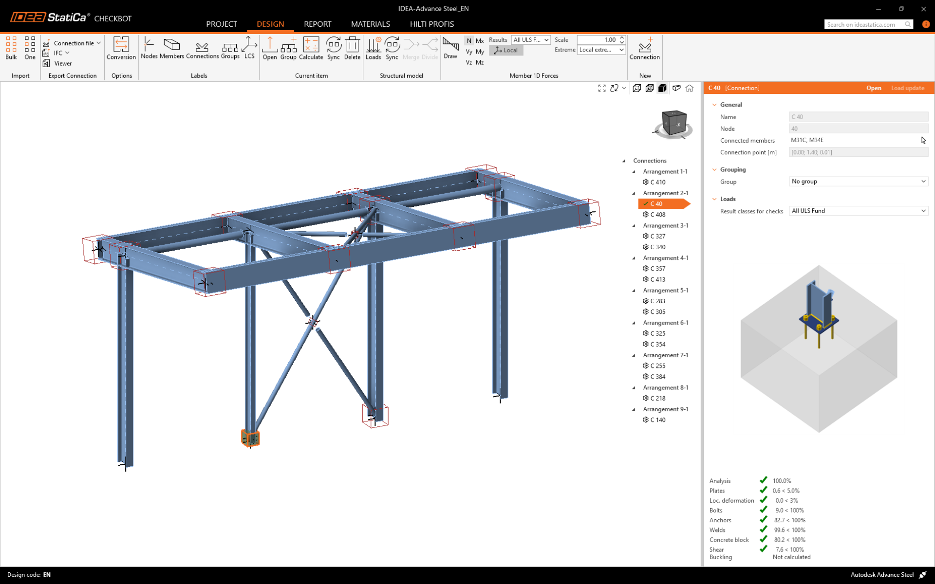
A fent bemutatott megközelítéssel folytathatja a további kapcsolatok tervezését.
Modell szinkronizálása
Néha változások történnek a VEM/BIM modellben, például eltérő szerkezeti elem keresztmetszetek vagy terhek. Ezek szinkronizálhatók a Checkbot és a VEM/BIM modell között.
Két lehetséges alternatíva létezik:
- Az aktuális elem szinkronizálása (ha egy vagy több csomópont van kijelölve)
- A teljes importált szerkezeti modell szinkronizálása

A funkció teszteléséhez megváltoztathatja egy szerkezeti elem keresztmetszetének méretét vagy alakját a BIM alkalmazásban, vagy módosíthat egy teherkombinációt stb.: módosítsa a kijelölt oszlopot kisebb keresztmetszetre.

A Checkbotban jelölje ki a tervezett kapcsolatokat (egynél több is lehet), majd az Aktuális elem panelen válassza a Szinkronizálás lehetőséget.
A Checkbot projekt frissül, a kapcsolat tervezése megmarad, de az eredmények érvénytelenné válnak. Látható, hogy az oszlop most frissült – megfelel a BIM modellben végrehajtott változtatásnak.
Egyszerűen végezze el újra a kiemelt kapcsolatok szabványellenőrzését az Aktuális elem panelen a Számítás lehetőség kiválasztásával. Ne feledje, hogy a modell nagyobb változásai további ellenőrzési lépéseket igényelhetnek az érintett kapcsolatoknál (mint fentebb).

Ha a kapcsolatok nem adják a kívánt eredményeket, akkor újra megnyithatja őket a terv optimalizálása érdekében (azaz megerősítheti, ha nem felelnek meg a szabványellenőrzésen, vagy könnyíthet rajtuk, ha a kihasználtság túl alacsony).
Sikeresen összekapcsolta az Advance Steel-t az IDEA StatiCa Connection-nel a Checkbot-on keresztül.
Olvasson többet az Advance Steel BIM link ismert korlátairól.