Cracks in concrete - the nightmare of engineers?
So much trouble with cracking, such complicated calculations, no wonder if you ever asked yourself: is it even worth it? Thanks to the now available sophisticated tools out there, we can luckily say that the answer is „Yes, it is!”
Concrete is fantastic in compression. That we all know, but in real structures, one cannot avoid having some parts in tension. Steel reinforcement provides higher tensile strength and ductility. A reinforced concrete structure can resist both tension and compression well, assuming that the reinforcement is appropriately placed and its amount is chosen wisely.
Serviceability is just as important
While strength in structures can seem like the most critical parameter, we can never omit the serviceability factors. A lot of times, they decide on the functionality and usability of an object. Too big deflections can make a structure look not only unsafe but also hard to fulfill its function. Similarly, if cracks go beyond a certain limit in terms of width, the concrete structure becomes esthetically unpleasing, and reinforcement will be subjected to corrosion, too.

Cracks in concrete pose a whole separate challenge for every structural engineer who is doing concrete design. How easy would it all be without having to deal with cracks? Unfortunately, they are and will be a part of every concrete structure – at least for the foreseeable future –, so we had to find ways to help engineers calculate with cracks on an everyday basis. The goal was to develop a tool that can deal with various shapes of concrete structures and considers the real positioning of reinforcement, not only some simplified predefined structural members. Engineers are familiar with simple hand calculations for the basic beams and columns, but modern structures come in all shapes – so modern tools have to give them a solution for general shapes, too. Calculating crack appearance and crack width is not an exception.
Crack calculation in CSFM
Our innovative method, CSFM (Compatible Stress Field Method) that is implemented in IDEA StatiCa Concrete, enables engineers to design concrete structures of any shape quickly and easily, including the calculation of crack widths.
The method's advanced state is based on modified compression field theory, implementation of tension stiffening, and distinguishing between stabilized or nonstabilized cracking. According to the valid Eurocode and ACI standards, we perform serviceability limit state checks of the concrete members, such as crack width, deformation, and stress limitation checks.
Let’s talk a bit about how our crack calculation works and what is it based on. For those interested in the full theoretical explanation of the calculation and the whole method, we recommend reading the Theoretical background for IDEA StatiCa Detail.
CSFM differentiates between stabilized and nonstabilized crack growth. Stabilized crack growth means uniformly distributed cracks – for example, along the lower edge of a beam. In the case of fully developed stabilized cracks, the Tension Chord Model (TCM) is used to calculate tension stiffening.
Nonstabilized crack growth is considered for local cracks triggered by geometrical discontinuities (e.g., regions where the cross-section changes, concave corners, etc.) and regions with a low reinforcement ratio. In such cases, the crack is nonstabilized, and tension stiffening is considered with the aid of the Pull-Out Model (POM).
But what is the tension stiffening effect that we keep talking about? It can be described as the effect of concrete acting in tension between cracks on the stress of steel reinforcement, which leads to increased stiffness.

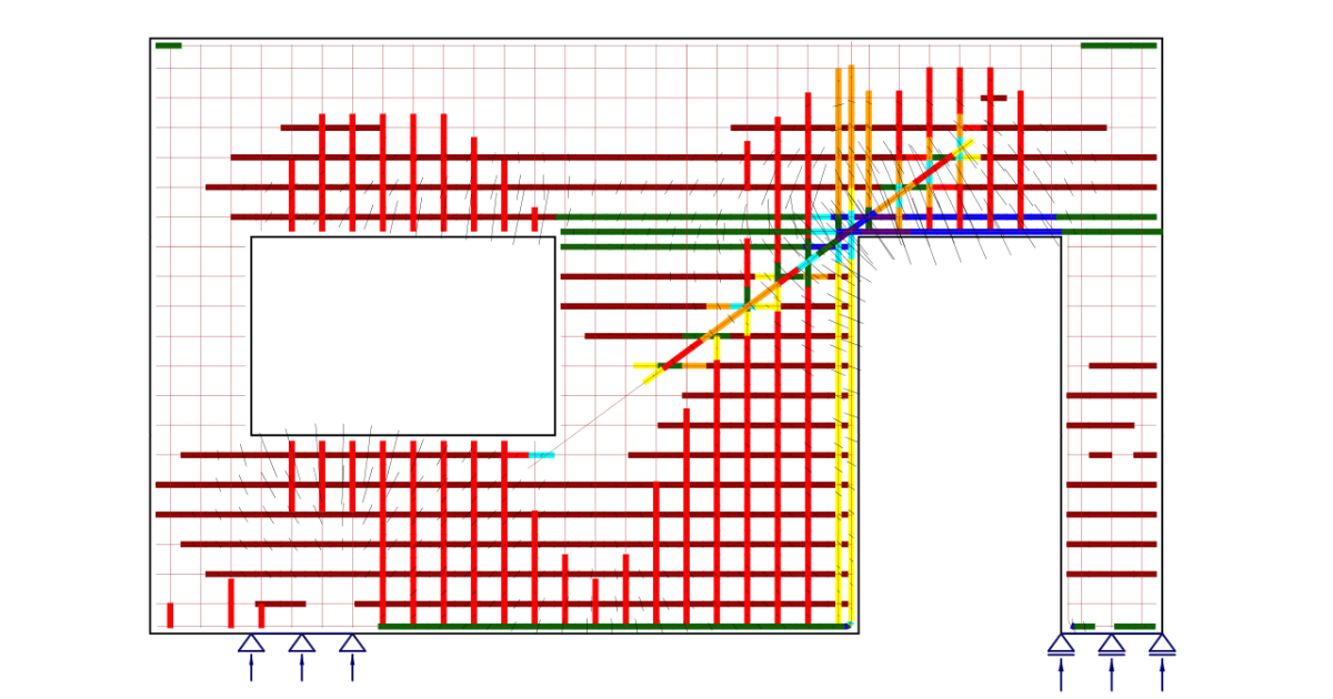
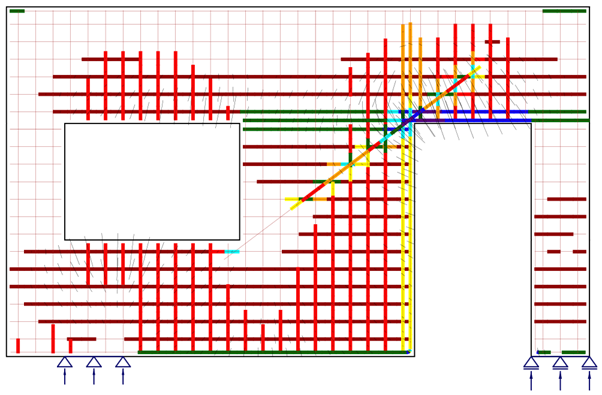
Concerning the fact that in the TCM, tension stiffening depends on the reinforcement area and its assignment to each reinforcement bar or layer, the determination of the pertinent (mutually acting) concrete surface under effective strain is critical. For this reason, we implemented an automatic spatial identification of the corresponding effective concrete surface mutually acting in tension for an arbitrary reinforcement configuration.
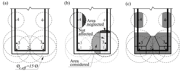
Crack distance
The maximum distance between cracks stabilizes at a value at which the stress in concrete between two neighboring cracks does not reach the stress value of the crack initiation limit state. In this way, the growth of further cracks is ended.
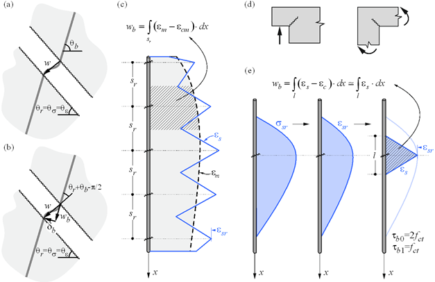
On the other hand, the Pull-Out Model analyses the behavior of individual cracks without considering the mechanical interaction between other cracks. It neglects the behavior of concrete in tension and assumes the same ideally rigid-plastic behavior in cohesion used in the Tension Chord Model. Given that the crack spacing isn’t known for a non-fully developed crack pattern, the average strain is computed for any load level over the distance between points with zero slip when the reinforcing bar reaches its tensile strength at the crack.

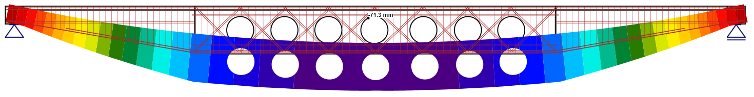
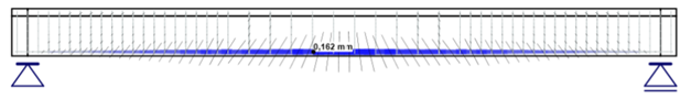
Crack width
Crack width is an essential condition for the serviceability limit state.
The calculation of crack width is performed for the permanent load. Two main models are available, as described above, the model of stabilized crack growth and the model of nonstabilized crack growth. Both these models depend on the type of reinforcement, on the automatically calculated reinforcement ratio, and subsequently on the tension stiffening of every individual 1D element used to model the reinforcement.
The width of a crack perpendicular to the orientation of the reinforcement „wb“ is calculated based on the models mentioned above via tension stiffening using the integration of strain over reinforcement. For regions with stabilized crack growth, the mean values of the strain of the reinforcement are calculated and integrated over the mean crack distance. In the case of nonstabilized crack growth, the width „wb“ is calculated based on the maximum stress in the reinforcement, which in this case is more reliable than mean strain.
Special situations are observed at concave corners of the calculated structures. In this case, the corner predefines the position of a single crack that behaves in a nonstabilized fashion before additional adjacent cracks develop. These additional cracks generally develop after the serviceability range, which justifies calculating the crack widths in such a region as if they were nonstabilized.

To sum it up
IDEA StatiCa Concrete is a tool for the safe evaluation of concrete structures, including the calculation of cracks.
Of course, this approach can not predict the exact position of future cracks in real structures but still produces relevant results that can be compared with values required by the code. The method naturally does not enable the evaluation of cracks in concrete areas where reinforcement is completely absent. Reinforced concrete structures of any shape can be designed and checked within a reasonable timeframe.
The calculation method of CSFM has been thoroughly tested and verified. More about the verifications you can read either in this article about verification of structural elements or in the Theoretical background for verification according to Eurocode.
CSFM is a transparent method that provides the structural engineer with control over the behavior of the structure. To find out more about the method and its application look at our webinar about Reinforced concrete design via CSFM.
Try for FREE
Feel free to validate CSFM and its use for the calculation of cracks in concrete structures by yourself. Try out our latest version of IDEA StatiCa Concrete for 14 days absolutely for FREE. And for sure, let us know your feedback! We are always keen to hear about your experience.
