IDEA StatiCa RCS – Calcul structurel des éléments en béton 2D
Calcul des sections en béton armé selon EN 1992-1-1 et EN 1992-2.
Types d'éléments 2D
Dalle
Selon EN 1992-1-1, art. 5.3.1(4), une dalle est un élément dont la dimension minimale du panneau n'est pas inférieure à 5 fois l'épaisseur totale de la dalle. La dalle est chargée uniquement par des moments fléchissants et des efforts tranchants perpendiculaires au plan centroïdal de la dalle. La vérification des dispositions constructives est effectuée selon EN 1992-1-1, art. 9.3.
Coque en tant que dalle – Shell-slab
La géométrie est définie de manière similaire à la définition de la géométrie d'une dalle. Contrairement à la dalle, la shell-slab peut être chargée par des actions de flexion et membranaires. Les dispositions constructives sont vérifiées selon les règles applicables aux dalles (EN 1992-1-1, art. 9.3).
Voile
Selon EN 1992-1-1, art. 5.3.1(7), un voile est un élément pour lequel les principes suivants ne sont pas satisfaits :
- la hauteur de la section ne dépasse pas 4 fois sa largeur
- la hauteur est au moins 3 fois la hauteur de la section
Le voile est chargé uniquement par des actions membranaires et les dispositions constructives sont vérifiées selon EN 1992-1-1, art. 9.6.
Coque en tant que voile – Shell-wall
La géométrie est définie de manière similaire à la définition de la géométrie d'un voile. Contrairement au voile, la shell-wall peut être chargée par des actions de flexion et membranaires. Les dispositions constructives sont vérifiées selon les dispositions constructives applicables aux voiles (EN 1992-1-1, art. 9.6).
Poutre voile
Selon EN 1992-1-1, art. 5.3.1(3), une poutre voile est un élément dont la portée est inférieure à 3 fois la hauteur totale de la section. La poutre voile peut être chargée, comme le voile, uniquement par des actions membranaires. Les dispositions constructives sont vérifiées selon EN 1992-1-1, art. 9.7.
Ferraillage pour éléments 2D
Un élément de coque de 1m x 1m est défini pour la vérification. Le ferraillage est saisi dans cet élément de coque. Le ferraillage par mètre linéaire est pris en compte pour la vérification de l'élément 2D.
Des modèles de ferraillage prédéfinis peuvent être utilisés pour saisir le ferraillage aux bords supérieur et inférieur. Il est possible de saisir un ferraillage général dans la dalle.
La saisie du ferraillage à l'aide de modèles de ferraillage
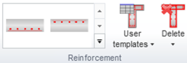
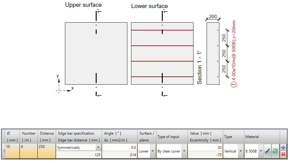
IDEA RCS fournit deux modèles pour la saisie du ferraillage dans un élément 2D. Un modèle est destiné à la saisie du ferraillage en surface supérieure, l'autre à la saisie du ferraillage en surface inférieure.
Les deux modèles permettent la saisie d'un ferraillage orthogonal aux surfaces de l'élément 2D. Les deux modèles permettent la rotation du ferraillage autour de l'axe x local de l'élément 2D.
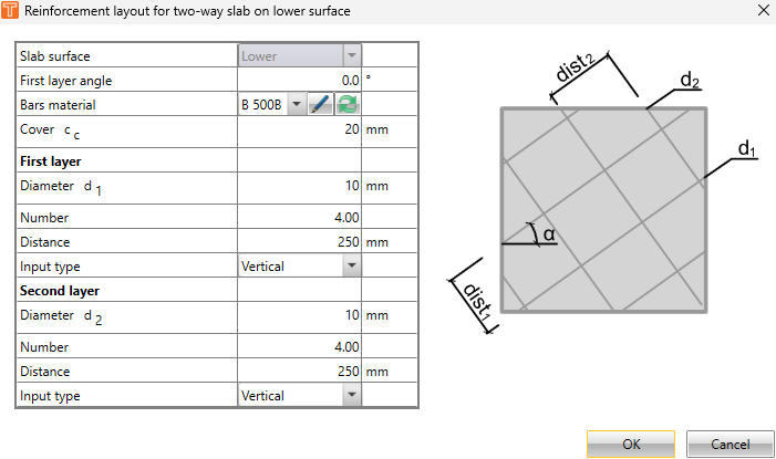
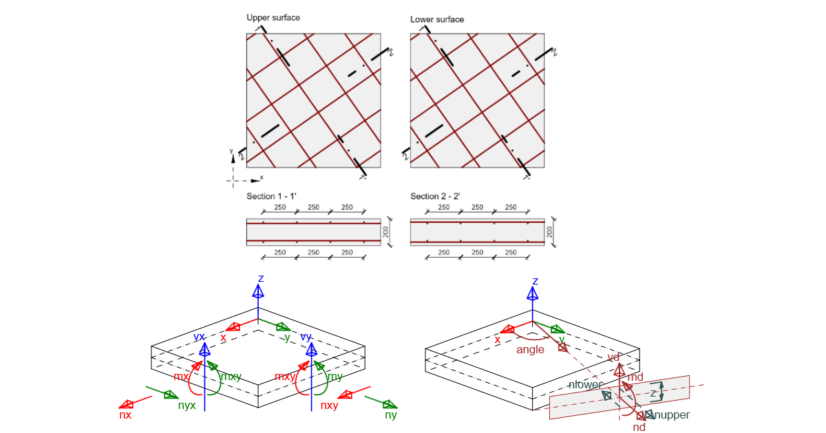
\[ \textsf{\textit{\footnotesize{Dialog for the definition of 2D reinforcement}}}\]
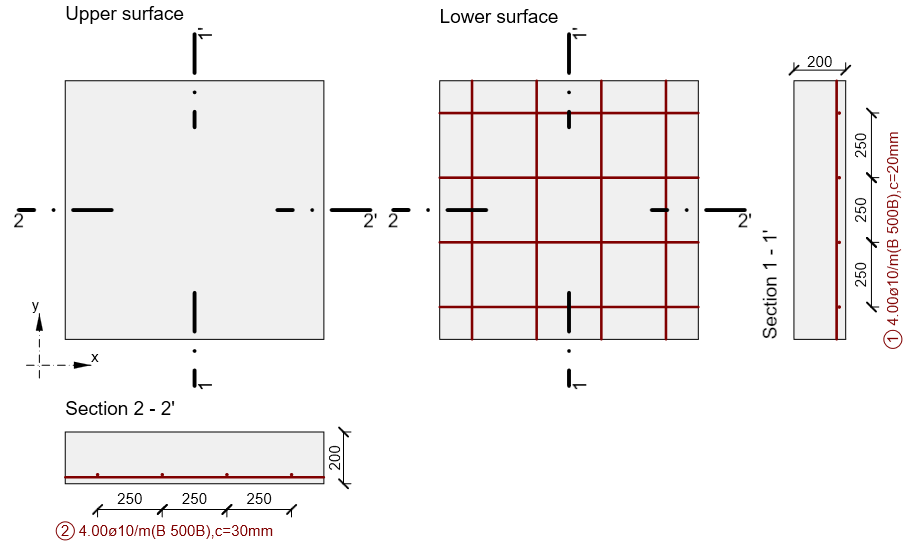
\[ \textsf{\textit{\footnotesize{Schema of defined reinforcement at the lower surface of 2D element}}}\]
La saisie du ferraillage général
Chaque couche de ferraillage est définie dans la section et dans le plan.
\[ \textsf{\textit{\footnotesize{General input}}}\]
Type de ferraillage
Le type de barre de ferraillage doit être défini pour pouvoir effectuer la vérification des dispositions constructives. Pour les éléments 2D de type
- Dalle et coque-dalle – pour les vérifications selon EN 1992-1-1, art. 9.3.1.1
- Ferraillage principal
- Ferraillage de répartition
- Voile, coque-voile et poutre voile – pour la vérification selon EN 1992-1-1, art. 9.6.2 et 9.6.3
- Ferraillage horizontal
- Ferraillage vertical
| Remarque : |
| Le ferraillage de répartition des dalles et coques-dalles est pris en compte uniquement pour la vérification des dispositions constructives ; il n'est pas utilisé dans les autres vérifications des éléments 2D. |
Forces internes pour les sections 2D
La saisie des forces internes
La saisie des forces internes des éléments 2D dépend du type d'élément 2D :
- Shell-slab – les forces membranaires (nx, ny et nxy), les moments fléchissants (mx, my et mxy) et les efforts tranchants (vx et vy) peuvent être saisis
- Shell- wall – les forces membranaires (nx, ny et nxy), les moments fléchissants (mx, my et mxy) et les efforts tranchants (vx et vy) peuvent être saisis
- Slab – seuls les moments fléchissants (mx, my et mxy) et les efforts tranchants (vx et vy) peuvent être saisis
- Wall – seules les forces membranaires (nx, ny et nxy) peuvent être saisies
- Deep beam – seules les forces membranaires (nx, ny et nxy) peuvent être saisies
| Description | |
| mx(y) | Moment fléchissant dans la direction de l'axe x (y). Une valeur positive provoque une traction à la surface inférieure d'un élément 2D. |
| mxy(yx) | Moment de torsion autour de l'axe y (x) agissant sur le bord parallèle à l'axe x (y). Une valeur positive provoque une contrainte de cisaillement de traction à la surface inférieure d'un élément 2D. Étant donné que le théorème d'égalité des contraintes de cisaillement horizontales est valable en chaque point de l'élément 2D, les moments de torsion mxy = myx sont également égaux en chaque point de l'élément 2D. Ainsi, seule la valeur de mxy est saisie dans le programme. |
| nx(y) | Effort normal dans la direction de l'axe x (y). Une valeur positive agit dans la direction de l'axe x(y) et provoque une traction dans la section. |
| nxy(yx) | Effort normal agissant dans le plan médian dans la direction de l'axe y(x) sur le bord parallèle à l'axe x(y). Une valeur positive agit dans la direction de l'axe x(y). Étant donné que le théorème d'égalité des contraintes de cisaillement horizontales est valable en chaque point de l'élément 2D, les efforts normaux nxy = nyx sont également égaux en chaque point de l'élément 2D. Ainsi, seule la valeur de nxy est saisie dans le programme. |
| vx(y) | Effort tranchant agissant perpendiculairement au plan médian sur le bord parallèle à l'axe x(y). Une valeur positive agit dans la direction de l'axe z. |
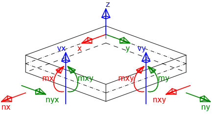
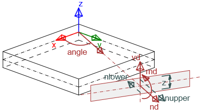
\[ \textsf{\textit{\footnotesize{Sign convention of internal forces}}}\]
Les types de combinaisons suivants doivent être définis pour les vérifications :
- État limite ultime/Accidentel – les composantes des forces internes définies pour ce type de combinaisons sont utilisées pour les vérifications à l'ELU des éléments 2D :
- Capacité N-M-M
- Réponse N-M-M
- Interaction
et la vérification des dispositions constructives
- Caractéristique – les composantes des forces internes définies pour ce type de combinaison sont utilisées pour la vérification de la limitation des contraintes (ELS)
- Quasi-permanent – les composantes des forces internes définies pour ce type de combinaison sont utilisées pour la vérification de l'ouverture des fissures (ELS)
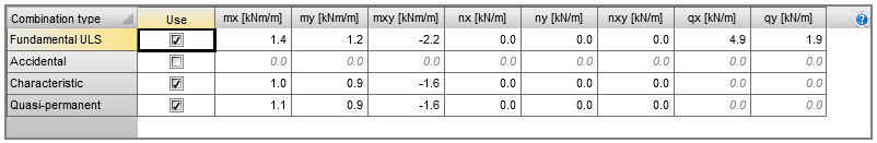
| Remarque : |
| Les composantes des forces internes vx et vy ne sont pas requises pour les types de combinaison Caractéristique et Quasi-permanent, car ces valeurs ne sont pas utilisées dans les vérifications. |
Détermination de la direction de vérification
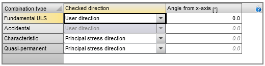
La direction de vérification doit être déterminée pour une vérification correcte de l'élément 2D. La direction de vérification peut être saisie pour chaque type de combinaison séparément, en utilisant les deux méthodes suivantes :
- Direction définie par l'utilisateur – l'utilisateur définit la direction de vérification comme un angle par rapport à l'axe x dans le plan de l'élément 2D. Cette option est définie par défaut pour le type de combinaison ELU et la valeur prédéfinie de l'angle est 0 degré. Les vérifications sont effectuées dans les directions suivantes :
- Direction définie
- Direction perpendiculaire à la direction définie
- Direction de la diagonale comprimée à la surface supérieure
- Direction de la diagonale comprimée à la surface inférieure
- Direction des contraintes principales – la direction de vérification est calculée automatiquement comme la direction des contraintes principales à la surface supérieure et à la surface inférieure de l'élément 2D. Cette option est définie par défaut pour les types de combinaison Caractéristique et Quasi-permanent. Les vérifications sont effectuées dans les directions suivantes :
- Direction des contraintes principales à la surface inférieure
- Direction perpendiculaire à la direction des contraintes principales à la surface inférieure
- Direction de la diagonale comprimée à la surface inférieure
- Direction des contraintes principales à la surface supérieure
- Direction perpendiculaire à la direction des contraintes principales à la surface supérieure
- Direction de la diagonale comprimée à la surface supérieure
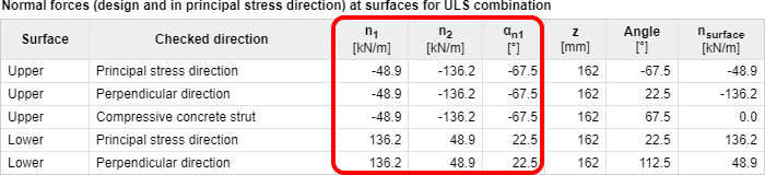
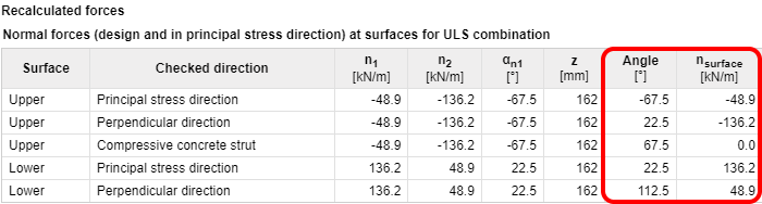
\[ \textsf{\textit{\footnotesize{Recalculated internal forces in input direction by theory of Baumann}}}\]
Analyse de la direction de vérification pour l'état limite ultime
Analyse 1
Pour un élément 2D chargé uniquement par des moments fléchissants (mx = 20 kNm/m, my = 10 kNm/m, mxy = 5 kNm/m) avec l'angle du ferraillage et l'angle de la direction de vérification modifiés pour l'état limite ultime, les résultats sont affichés dans le graphique suivant :
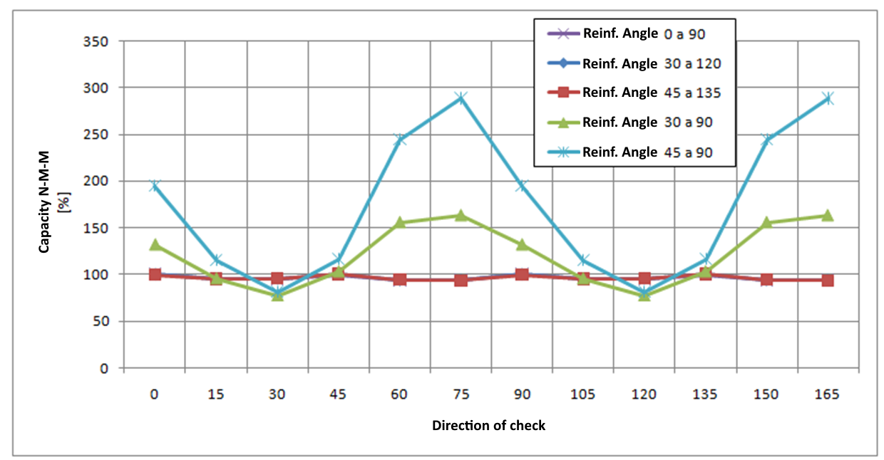
L'analyse implique :
- Si les barres de ferraillage sont perpendiculaires entre elles, les résultats de vérification sont similaires pour différents angles de direction de vérification, ils ne dépendent pas de l'angle de ferraillage défini et la valeur maximale de la vérification est trouvée pour les angles 0, 45 et 90 degrés. Ainsi, cette vérification peut être effectuée pour une direction prédéfinie d'un angle de vérification de 0 degré.
- Si les barres de ferraillage ne sont pas perpendiculaires entre elles, les résultats des vérifications diffèrent significativement et la valeur maximale de vérification est atteinte approximativement dans la direction correspondant à la direction du ferraillage moyen. Il est donc recommandé de modifier la direction de vérification prédéfinie ou d'effectuer des vérifications dans plusieurs directions lorsque les barres de ferraillage ne sont pas perpendiculaires entre elles.
Analyse 2
Pour le ferraillage orthogonal, les valeurs des moments fléchissants et l'angle ont été modifiés pour la vérification normative à l'ELU. Les résultats sont représentés dans le graphique :
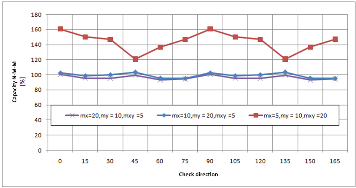
L'analyse implique que même pour différentes valeurs de moments fléchissants, la valeur maximale de la vérification à l'état limite ultime est trouvée pour les directions de vérification 0, 45 et 90 degrés. Ainsi, la vérification peut être effectuée pour un angle de vérification prédéfini de 0 degré. Une conclusion similaire est valable pour les éléments 2D chargés uniquement par un effort normal ou chargés par un effort normal combiné à des moments fléchissants.
Recalcul des forces internes dans les directions de vérification
Les forces internes définies sont recalculées dans les directions de vérification à l'aide de la formule de transformation de Baumann, décrite dans Baumann, Th. : "Zur Frage der Netzbewehrung von Flächentragwerken". In : Der Bauingenieur 47 (1972), Berlin 1975. La procédure de calcul est la suivante :
- Calcul des efforts normaux aux deux surfaces de l'élément 2D
- Calcul des efforts principaux aux deux surfaces de l'élément 2D
- Calcul des efforts recalculés pour chaque surface dans la direction de vérification définie
- Calcul des efforts recalculés pour chaque surface vers le centre
- Recalcul des efforts tranchants dans la direction de vérification définie
Calcul des efforts normaux aux deux surfaces de l'élément 2D
Les forces internes définies sont recalculées aux deux surfaces à l'aide des formules suivantes :
\[{{n}_{x,low\left( upp \right)}}=\frac{{{n}_{x}}}{2}+\left( - \right)\frac{{{m}_{x}}}{z}\]
\[{{n}_{y,low\left( upp \right)}}=\frac{{{n}_{y}}}{2}+\left( - \right)\frac{{{m}_{y}}}{z}\]
\[~~~~~{{n}_{xy,low\left( upp \right)}}=\frac{{{n}_{xy}}}{2}+\left( - \right)\frac{{{m}_{xy}}}{z}\]
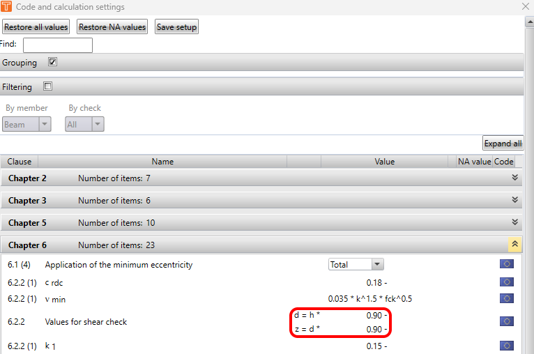
Le bras de levier des forces internes (z) doit être déterminé pour le recalcul des forces internes. Le bras de levier des forces internes est déterminé à partir de la méthode de déformation limite sous chargement par le moment fléchissant principal dans les directions des moments principaux m1 aux deux surfaces. Si les moments principaux sont égaux à zéro ou si l'équilibre n'est pas trouvé dans la direction des moments principaux, le bras de levier des forces internes est déterminé selon la formule :
\[z=x\cdot d\]
| Description | |
| x | Le coefficient pour le calcul du bras de levier des forces internes est défini dans la configuration du code national. |
| d | La hauteur utile de la section transversale calculée séparément pour les surfaces supérieure et inférieure de l'élément 2D. Pour la surface inférieure, il s'agit de la distance entre le centre de gravité des barres de ferraillage à la surface inférieure et le bord supérieur de la section transversale. Pour la surface supérieure, il s'agit de la distance entre le centre de gravité des barres de ferraillage à la surface supérieure et le bord inférieur de la section transversale. |
| Remarque : |
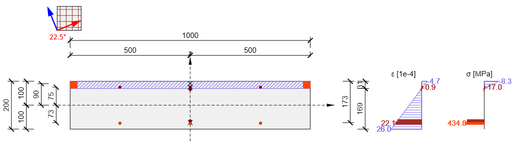
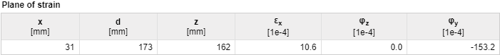
| Le bras de levier des forces internes peut être vérifié dans la vérification Réponse N-M-M. Seuls les moments fléchissants doivent être saisis et la direction de vérification doit correspondre à la direction du moment principal. |
Dans le diagramme suivant, une vérification du bras de levier des forces internes est affichée pour les moments fléchissants mx = 20 kNm/m, my = 10 kNm/m, mxy = 5 kNm/m. La direction des moments principaux a été calculée comme αm1 = 22,5 degrés et la réponse de la section transversale a été calculée pour déterminer le bras de levier des forces internes.
| Remarque : |
| Les bras de levier des forces internes pour le recalcul des forces internes dans la direction de vérification et les bras de levier des forces internes pour les vérifications peuvent être différents, car le bras de levier des forces internes pour le recalcul est déterminé sur une section transversale chargée par les moments principaux dans la direction des moments principaux, et le bras de levier des forces internes pour la vérification est déterminé sur une section transversale chargée par les moments fléchissants et les efforts normaux dans la direction de vérification. Les valeurs des bras de levier des forces internes pour tous les types de combinaison sont affichées dans le tableau Forces recalculées dans le navigateur Forces internes dans la section. |
Calcul des forces internes aux deux surfaces
Les efforts principaux aux deux surfaces de l'élément 2D sont calculés à l'aide de la formule :
\[{{n}_{1,bot\left( top \right)}}=\frac{{{n}_{x,low\left( upp \right)+}}{{n}_{y,low\left( upp \right)}}}{2}+\frac{1}{2}\sqrt{{{\left( {{n}_{x,low\left( upp \right)-}}{{n}_{y,low\left( upp \right)}} \right)}^{2}}+4\cdot {{n}_{xy,low\left( upp \right)}}}\]
\[{{n}_{2,bot\left( top \right)}}=\frac{{{n}_{x,low\left( upp \right)+}}{{n}_{y,low\left( upp \right)}}}{2}-\frac{1}{2}\sqrt{{{\left( {{n}_{x,low\left( upp \right)-}}{{n}_{y,low\left( upp \right)}} \right)}^{2}}+4\cdot {{n}_{xy,low\left( upp \right)}}}\]
Et la direction des efforts principaux est calculée à l'aide de la formule :
\[{{\alpha }_{n1,low\left( upp \right)}}=0,5\cdot {{\tan }^{-1}}\left( \frac{2\cdot {{n}_{xy,low\left( upp \right)}}}{{{n}_{x,low\left( upp \right)}}-{{n}_{y,low\left( upp \right)}}} \right)\]
| Remarque : |
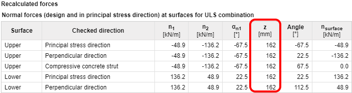
| Les efforts principaux et la direction des efforts principaux pour les deux surfaces de l'élément 2D sont affichés pour tous les types de combinaison dans le tableau Forces recalculées dans le navigateur Forces internes dans la section. |
Calcul des forces internes recalculées aux surfaces dans la direction de vérification définie
Le recalcul des efforts principaux dans les directions de vérification est effectué séparément pour chaque surface à l'aide de la formule de transformation de Baumann :
\[{{n}_{surface,i,low\left( upp \right)}}=\frac{{{n}_{1,low\left( upp \right)}}\cdot \sin \left( {{\alpha }_{j,low\left( upp \right)}} \right)\cdot \sin \left( {{\alpha }_{k,low\left( upp \right)}} \right)+{{n}_{2,low\left( upp \right)}}\cdot \cos \left( {{\alpha }_{j,low\left( upp \right)}} \right)\cdot \cos \left( {{\alpha }_{k,low\left( upp \right)}} \right)}{\sin \left( {{\alpha }_{j,low\left( upp \right)}}-{{\alpha }_{i,low\left( upp \right)}} \right)\cdot \sin \left( {{\alpha }_{k,low\left( upp \right)}}-{{\alpha }_{i,low\left( upp \right)}} \right)}\]
| Description | |
| i, j, k, i | Indice de la direction de vérification (direction de recalcul des forces internes) i, j, k, i = 1, 2, 3, 1. Par exemple, pour la surface inférieure et le calcul de la force dans la direction j (angle α2), la formule est : \[{{n}_{surface,2,low}}=\frac{{{n}_{1,low}}\cdot \sin {{\alpha }_{3,low}}\cdot \sin {{\alpha }_{1,low}}+{{n}_{2,low}}\cdot \cos {{\alpha }_{3,low}}\cdot \cos {{\alpha }_{1,low}}}{\sin \left( {{\alpha }_{3,low}}-{{\alpha }_{2,low}} \right)\cdot \sin \left( {{\alpha }_{1,low}}-{{\alpha }_{2,low}} \right)}\] |
| \[{{\alpha }_{i,j,k,low\left( upp \right)}}\] | L'angle entre la direction de vérification définie ou la direction de la bielle comprimée et la direction des efforts principaux à la surface inférieure ou supérieure de l'élément 2D. Direction de vérification définie α1, low(upp) = α1 – α low(upp) Dir. perpendiculaire à la direction définie α2, low(upp) = α2 – α low(upp) Direction de vérification pour la bielle comprimée α3, low(upp) = α3 – α low(upp) |
| α1 | Direction de vérification définie pour la combinaison particulière |
| α2 | La direction perpendiculaire à la direction définie, α2 = α1 + 90 degrés |
| α3 | Vérifier la direction dans la direction de la bielle comprimée dans le plan de l'élément 2D. Cette direction est optimisée pour minimiser l'effort dans cette direction. |
| Remarque : |
Si la direction de vérification est identique à la direction des contraintes principales, les efforts dans la bielle comprimée sont nuls, cette direction est donc négligée dans la vérification. La direction de la bielle comprimée pour tous les états de contrainte à l'exception de l'état de contrainte hyperbolique (n1,low(upp) > 0 et n1,low(upp) < 0) peut être calculée selon la formule : α3 = 0,5(α1 + α2) Les forces internes recalculées pour les deux surfaces de l'élément 2D et toutes les directions de vérification, y compris la direction de la bielle comprimée, sont affichées dans le tableau Forces recalculées |
Transformation des forces internes recalculées vers le centre de gravité de la section transversale
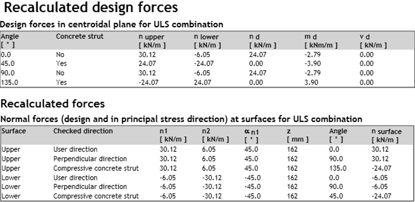
Pour la vérification de l'élément 2D, les forces de surface dans une direction particulière doivent être recalculées vers le centre de gravité de la section transversale. Le résultat est un effort normal nd,i et un moment fléchissant md,I agissant au centre de gravité de la section transversale de l'élément 2D.
md,i = nlower,i·zs,low + nupper,i·zs,upp
nd,i = nlower,i + nupper,i
| Description | |
| nlower,i | Forces de surface recalculées à la surface inférieure dans la ième direction de vérification, lorsque nlower,i = nsurface,low,i. |
| nupper,i | Forces internes recalculées à la surface supérieure dans la ième direction de vérification, lorsque nupper,i = nsurface,upp,i. |
| zs,low (upp) | Distance du centre de gravité du béton comprimé ou du centre de gravité du ferraillage à la surface inférieure (supérieure), lorsque z = zs,low + zs,upp |
| Remarque : |
| Si les directions des bielles comprimées à la surface inférieure et à la surface supérieure sont différentes, pour le recalcul des forces vers le centre de gravité, il est nécessaire de calculer des forces virtuelles à la surface inférieure dans la direction de la bielle comprimée à la surface supérieure et vice versa. |
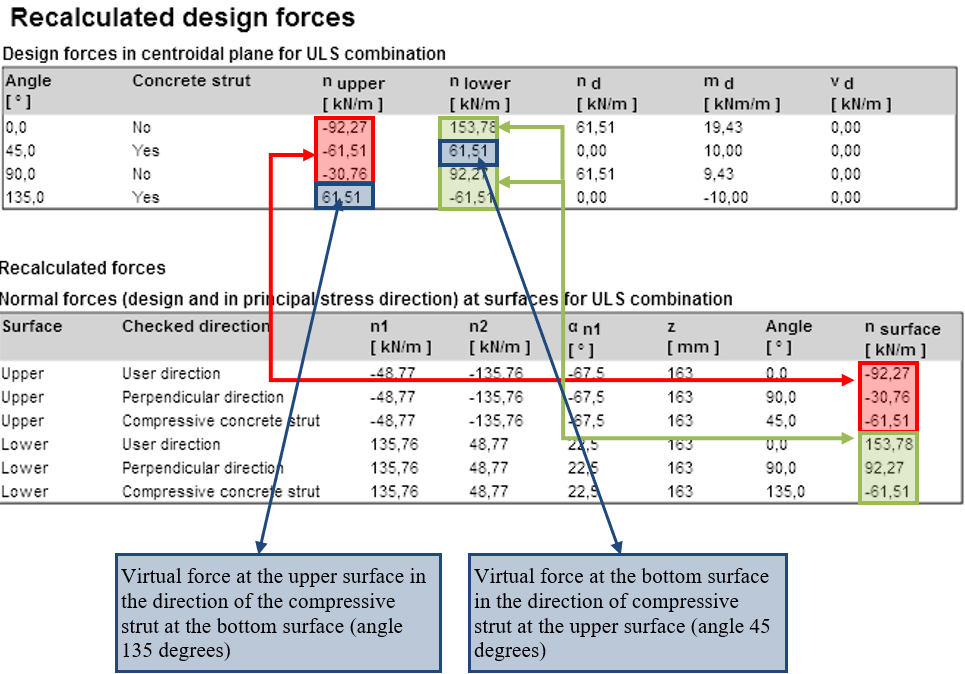
\[ \textsf{\textit{\footnotesize{Recalculated design forces}}}\]
Recalcul des efforts tranchants dans la direction de vérification définie
Les efforts tranchants sont recalculés dans la direction de vérification à l'aide de la formule :
\[{{v}_{d,i}}={{v}_{x}}\cdot \cos ({{\alpha }_{i}})+{{v}_{y}}\cdot \sin ({{\alpha }_{i}})\]
et l'effort tranchant maximal est :
\[{{v}_{d,max~}}=\sqrt{{{v}_{x}}^{2}+{{v}_{y}}^{2}}\]
et il agit dans la direction
\[\beta ={{\tan }^{-1}}\left( \frac{{{v}_{y}}}{{{v}_{x}}} \right)\]
| Description | |
| αi | Vérifier l'angle dans la ième direction |
| Remarque : |
| Lors de la vérification d'un élément 2D avec des efforts tranchants relativement importants, il est approprié de vérifier l'élément 2D dans la direction de l'effort tranchant maximal, ce qui signifie que la direction de vérification définie correspond à l'angle β |
Comparaison du recalcul des forces internes selon différentes méthodes
Recalcul des forces selon EN 1992-1-1
La méthode décrite dans EN 1992-1-1 est utilisée dans plusieurs programmes et en pratique pour calculer les forces internes de calcul. EN 1992-1-1 ne prend en compte que les directions de ferraillage perpendiculaires. Le calcul des forces de dimensionnement avec l'influence du moment de torsion est décrit dans l'organigramme suivant, où my³ mx. Un diagramme similaire peut être créé pour les moments my < mx
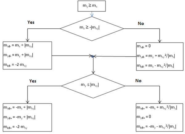
| Description | |
| mxd+, mxd- | Moment fléchissant de dimensionnement dans la direction de l'axe x pour le calcul et la vérification du ferraillage à la surface inférieure (-) ou supérieure (+) |
myd+ myd- | Moment fléchissant de dimensionnement dans la direction de l'axe y pour le calcul et la vérification du ferraillage à la surface inférieure (-) ou supérieure (+) |
| mcd+, mcd- | Moment fléchissant de dimensionnement dans la bielle comprimée en béton à la surface inférieure (-) ou supérieure (+), qui doit être repris par le béton |
Les valeurs des forces de dimensionnement recalculées pour le type d'élément = Dalle, calculées selon la méthode décrite dans l'EN, sont affichées dans le tableau suivant :
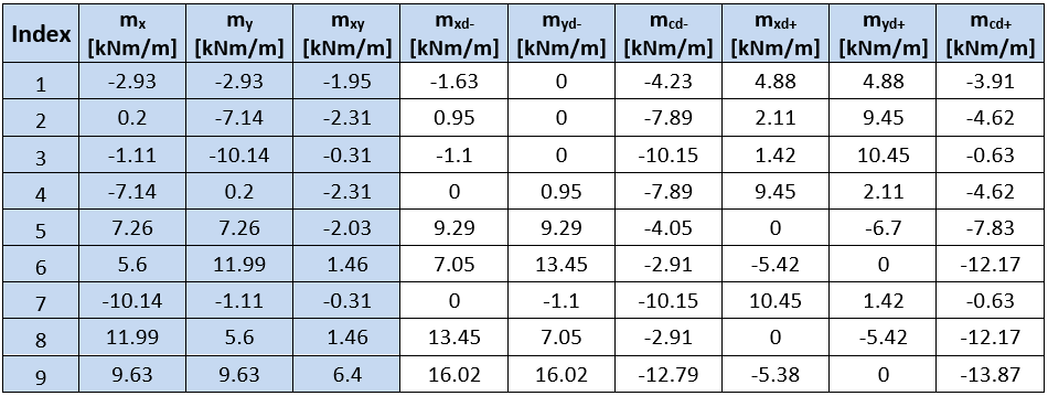
Dans IDEA StatiCa RCS, les valeurs des moments à la surface supérieure et inférieure ne sont pas affichées, mais les valeurs des efforts normaux aux deux surfaces et les valeurs des moments recalculés vers le centre de gravité de la section transversale.
Les moments aux surfaces inférieure et supérieure peuvent être calculés à l'aide des forces de surface, qui sont affichées dans la sortie numérique, en utilisant la formule :
\[{{m}_{surface,i,dlow\left( upp \right)}}={{n}_{surface,i,low\left( upp \right)}}\cdot z\]
Les valeurs des forces de surface et des moments recalculés sont affichées dans les tableaux suivants :
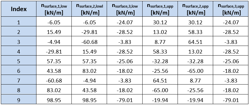
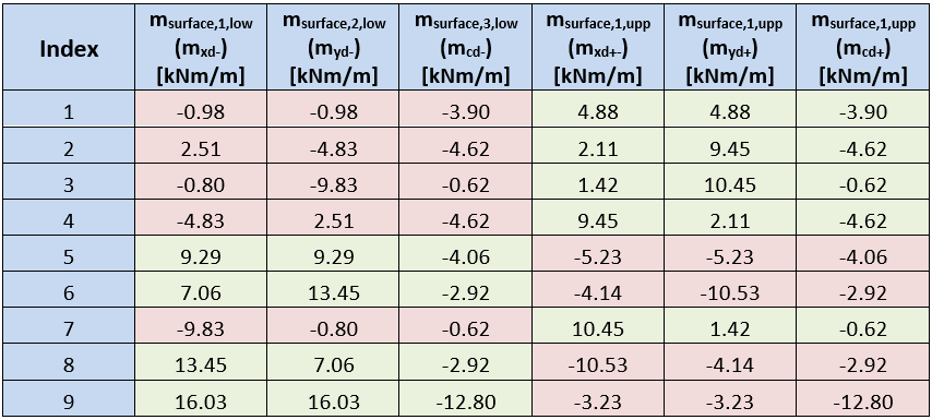
Les tableaux montrent que les moments aux surfaces de la dalle calculés dans IDEA Concrete et calculés selon la méthode décrite dans l'EN ne correspondent qu'à une seule surface. Cette différence est due à une optimisation différente de la bielle comprimée en béton. La méthode utilisée dans IDEA StatiCa RCS recherche l'angle de la bielle comprimée à l'effort minimal dans la bielle. La méthode décrite dans l'EN recherche une somme minimale des efforts négatifs de toutes les directions.
Comparaison du calcul des forces internes avec les programmes RFEM et SCIA Engineer
Pour comparer les résultats des forces internes recalculées dans les programmes IDEA Concrete, RFEM et SCIA Engineer (SEN), un modèle simple de dalle de dimensions 6 m x 4 m et d'épaisseur 200 mm a été préparé. La dalle est appuyée sur des appuis linéaires aux bords et chargée par une charge uniforme de 10 kN/m2.
Pour simplifier la présentation, seules les valeurs des forces internes recalculées dans une section longitudinale sont affichées. La distance de la section par rapport au bord de la dalle est de 1,5 m. Les forces internes calculées dans le programme RFEM ont été utilisées comme valeurs d'entrée pour IDEA Concrete.
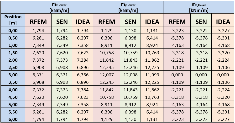
Le tableau montre une bonne concordance des forces calculées dans les différents programmes.
Vérification normative
Comme décrit dans Efforts internes dans le chapitre Transformation des efforts internes recalculés vers le centroïde de la section transversale, les forces de dimensionnement surfaciques sont transformées vers le centroïde d'une section transversale d'élément 2D. Le résultat de cette transformation est un moment fléchissant et un effort normal, agissant au centroïde d'une section transversale rectangulaire, dont la longueur de bord est de 1 m et la hauteur correspond à l'épaisseur de la dalle.
Les vérifications normatives de l'élément 2D sont effectuées simultanément dans toutes les directions définies. Le programme convertit automatiquement le ferraillage dans la direction de vérification à l'aide de la formule :
\[{{A}_{Si,\alpha }}={{A}_{S}}\cdot {{\cos }^{2}}({{\alpha }_{i}})\]
| Description | |
| Asi,a | L'aire de la ième couche de ferraillage recalculée dans la direction a |
| As | L'aire de la ième couche de ferraillage de l'élément 2D |
| αi | L'angle entre la ième couche de ferraillage et la direction de vérification |
| Remarque : |
| Le ferraillage de répartition dans les éléments 2D de type dalle et dalle-coque est pris en compte uniquement dans la vérification des dispositions constructives ; il n'est pas utilisé dans les autres vérifications des éléments 2D. |
Résultats des vérifications normatives dans les directions définies
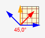
Toutes les vérifications normatives activées sont effectuées automatiquement dans toutes les directions requises. La présentation des résultats est similaire à celle des résultats des éléments 1D. La présentation pour les éléments 2D permet de définir la direction à afficher. Les résultats pour les éléments 2D sont présentés dans les directions de vérification. Toutes les directions dans lesquelles les vérifications ont été calculées sont représentées dans la présentation graphique.
Les flèches dans l'image représentent les directions de vérification, où la flèche orange indique la direction de la valeur de vérification maximale et la flèche rouge indique la direction de vérification courante. Pour modifier la direction courante, cliquez sur la flèche ou sur le bouton correspondant dans le ruban.
| Remarque : |
| À la fin du calcul, les directions de vérification dans toutes les vérifications normatives sont définies selon la direction du taux de travail maximal de la section transversale. |
Les résultats dans les vérifications particulières sont présentés dans la direction courante. L'angle de vérification est affiché au-dessus du tableau récapitulatif de la vérification.
Les résultats dans la direction extrême sont imprimés dans le rapport.
État limite ultime
Les principes des vérifications à l'ELU sont décrits dans le manuel de base théorique pour les éléments 1D. Seules les différences pour les éléments 2D sont décrites dans les chapitres suivants.
Vérification de la capacité
La vérification de la capacité ne diffère pas des vérifications des éléments 1D. La charge agit uniquement dans un plan, le type de vérification est donc N + M.
Vérification de la réponse
Les vérifications de la réponse pour les directions de vérification particulières utilisent les mêmes algorithmes que les vérifications des éléments 1D.
Vérification de l'interaction
Contrairement aux éléments 1D, la vérification de l'interaction est effectuée uniquement pour évaluer l'exploitation V + M, c'est-à-dire l'interaction entre le cisaillement et le moment fléchissant. Les valeurs VRd,c et VRd,max peuvent être vérifiées dans le tableau récapitulatif de la vérification d'interaction.
Comparaison de la vérification de capacité entre IDEA Concrete, RFEM et SCIA Engineer
Pour comparer les résultats de la vérification de capacité avec RFEM et SCIA Engineer, les mêmes données que celles décrites dans Efforts internes dans le chapitre Comparaison du calcul des efforts internes avec les programmes RFEM et SCIA Engineer ont été utilisées. La comparaison a été effectuée en deux points de la dalle.
Étant donné que les programmes RFEM et SEN ne vérifient pas le ferraillage réel dans la dalle, mais calculent uniquement l'aire de ferraillage nécessaire, deux méthodes ont été utilisées pour comparer le calcul. La première compare le taux de travail de la section transversale pour le ferraillage requis calculé dans RFEM et SEN, en supposant que la section transversale est exploitée à 100 % uniquement lorsque l'aire de ferraillage requise calculée est utilisée.
Le taux de travail de la section transversale ferraillée dans IDEA Concrete peut alors être exprimé de manière relative.
Taux de travail relatif = As, req / As, RCS × 100 [%]
| Description | |
| As, req | Aire de ferraillage requise calculée dans RFEM ou SEN |
| As, RCS | Aire de ferraillage dans IDEA Concrete |
| 100 [%] | Pourcentage |
La section transversale dans IDEA Concrete a été ferraillée à la surface inférieure avec un ferraillage d=10 mm espacé de 200 mm dans les deux directions ; l'aire de ferraillage dans les deux directions est de 314 mm2.
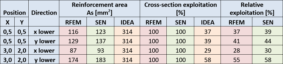
Le tableau montre une bonne concordance du taux de travail pour tous les programmes.
Un ferraillage d'aire approximativement égale au ferraillage requis calculé dans RFEM et SEN a été défini dans IDEA Concrete pour la deuxième méthode. Ensuite, le taux de travail de la section transversale a été comparé. Les résultats sont présentés dans le tableau suivant :
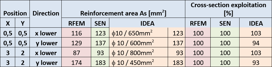
La bonne concordance des résultats est également vérifiée ici.
État limite de service
Limitation des contraintes
La vérification de la limitation des contraintes ne diffère pas des vérifications pour les éléments 1D.
Vérification de la largeur de fissure
En complément, les éléments 1D vérifient la direction de la fissure qui peut être représentée pour les éléments 2D.
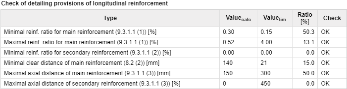
Dispositions constructives
La vérification des dispositions constructives des éléments 2D peut être divisée en deux groupes de base :
- Vérification du pourcentage de ferraillage
- Vérification des espacements entre barres
La vérification des dispositions constructives dépend également du type d'élément 2D. Des vérifications séparées pour le ferraillage principal et le ferraillage de répartition sont effectuées pour les éléments dalle-coque et dalle. Le ferraillage vertical et horizontal est distingué pour les éléments voile.
La vérification du pourcentage de ferraillage est effectuée dans la direction des contraintes principales. Le ferraillage défini dans la coupe de l'élément 2D (à l'exception du ferraillage de répartition) est transformé dans les directions des contraintes principales.
La vérification de l'espacement des barres est effectuée perpendiculairement à la direction du ferraillage défini. Cette vérification est effectuée pour toutes les couches de ferraillage définies et les valeurs limites dépendent du type d'élément vérifié et du type de ferraillage défini.