Notes de version IDEA StatiCa Steel 20
Introduction
La nouvelle version d'IDEA StatiCa est disponible ! C'est la plus grande intégration de retours et de souhaits de nos clients que nous ayons réalisée depuis des années. Et cela signifie quelque chose – IDEA StatiCa est utilisé par plus de 3 500 clients qui partagent plus de 4 000 projets IDEA StatiCa uniques chaque mois.
Comment sommes-nous passés du numéro 10 au 20 ? Le volume considérable de nouvelles fonctionnalités semble justifier le « +10 », mais la raison est plus simple – aligner la numérotation sur le compte des années. En 2020, nous publions IDEA StatiCa 20.
Cette version apporte un volume exceptionnel de nouvelles fonctionnalités et d'améliorations. Tout cela avec notre objectif de permettre aux ingénieurs de travailler plus rapidement, d'évaluer rigoureusement les exigences de la norme nationale et d'utiliser une quantité optimale de matériaux. Les points forts sont :
- Nouveau système de licence en ligne – plus de tracas liés à l'installation
- IDEA StatiCa peut désormais générer des « esquisses » pour accélérer le processus de détaillage
- 110 nouveaux modèles d'assemblage ajoutés à l'assistant de démarrage
- Les assemblages acier-bois peuvent désormais être dimensionnés et vérifiés
- Les bases de données de sections transversales sont désormais filtrées automatiquement en fonction de vos paramètres régionaux
- Les normes de Hong Kong et d'Inde sont désormais prises en charge
Nous espérons que vous apprécierez toutes nos nouvelles fonctionnalités et améliorations et serions ravis de recevoir vos retours à tout moment.
À noter, attendez-vous à une petite pause dans les nouvelles fonctionnalités pour l'acier pour le reste de l'année. La version d'automne 2020 sera axée sur le béton et le BIM.
Calculez les estimations d'hier !
Nouveau système de licences
Le nouveau système de licences en ligne d'IDEA StatiCa a été mis en place. Il est basé sur un compte, ce qui signifie que tout ce dont vous avez besoin pour démarrer IDEA StatiCa 20 est d'insérer votre nom d'utilisateur (par défaut, une adresse e-mail) et votre mot de passe.
Pourquoi ?
- Nos clients rencontraient des difficultés liées à la gestion des codes de licence, des fichiers de licence et des dongles.
- La licence IDEA StatiCa pouvait être corrigée sans la coopération de l'utilisateur final (réactivation, etc.).
- Nos clients devaient déployer la licence réseau sur leurs serveurs.
- La licence d'entreprise ne pouvait pas être facilement partagée avec les employés en déplacement ou en télétravail
Le nouveau système de licences en ligne d'IDEA StatiCa résout tous ces problèmes et bien plus encore. Tout est fourni dans un cloud IDEA StatiCa robuste et sécurisé, pour lequel les utilisateurs n'ont besoin que d'une seule chose pour y accéder – leur nom d'utilisateur (par défaut, une adresse e-mail) et leur mot de passe.
Comment fonctionne la licence en ligne ?
- L'installation d'IDEA StatiCa vérifie régulièrement auprès du serveur de licences IDEA StatiCa pour mettre à jour la licence et vérifier la configuration du produit.
- Les utilisateurs d'IDEA StatiCa n'ont pas besoin d'être connectés en permanence. La licence fonctionnera pendant 72 heures sans connexion Internet. Après cela, la connexion au serveur de licences est nécessaire.
- Les administrateurs, ainsi que les utilisateurs finaux, peuvent consulter/modifier la licence via le portail client IDEA StatiCa, un espace en ligne contenant leurs données de licence

Comment configurer IDEA StatiCa version 20
- Chaque client d'IDEA StatiCa dispose d'une adresse e-mail principale dans notre système (confirmée lors d'une commande passée)
- Avec la sortie de la version 20, IDEA StatiCa enverra les identifiants administrateur à cette adresse e-mail. La licence disposera de droits basés sur les produits achetés et le nombre de postes.
- Les administrateurs peuvent ensuite ajouter et supprimer d'autres utilisateurs dans l'organisation
- Chaque utilisateur de l'organisation ne peut utiliser que le type de produits IDEA StatiCa sélectionné

Gestionnaire de licences IDEA StatiCa
Avertissement concernant la migration
- IDEA StatiCa 20 ne dispose que d'une seule façon d'activer et de lancer le logiciel – le nouveau système de licences en ligne.
- Les anciens systèmes de licences (Eleckey, HASP) des versions jusqu'à 10.1 restent inchangés et fonctionnels. Les droits à vie (désormais appelés « Perpétuels ») fonctionneront indéfiniment, mais leur support technique sera arrêté le 30. 6. 2021. Après cette date, les réinitialisations de licence, les réactivations et tout autre support lié aux licences ne seront plus fournis. Veuillez vous assurer que votre organisation migre vers la version 20 dans les plus brefs délais.
IDEA StatiCa Connection
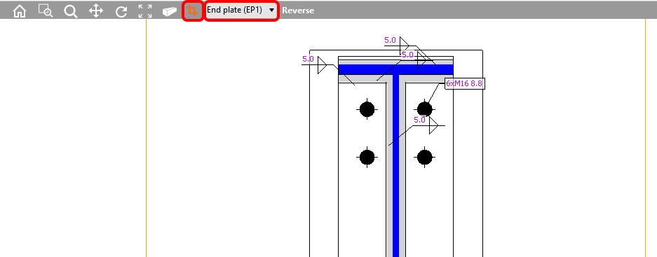
Vue du modèle de section – dessins (« croquis »)
Tous les ingénieurs structure, concepteurs et dessinateurs ont besoin de sorties visuelles claires de leurs projets. C'est pourquoi la possibilité d'ajuster les dessins était une fonctionnalité très demandée. Les ingénieurs souhaitent générer des « croquis », les dessinateurs aiment en recevoir pour ne pas partir de zéro lors de la mise en plan. Désormais, vous pouvez définir et modifier les modèles de section dans la fenêtre principale de la scène 3D.
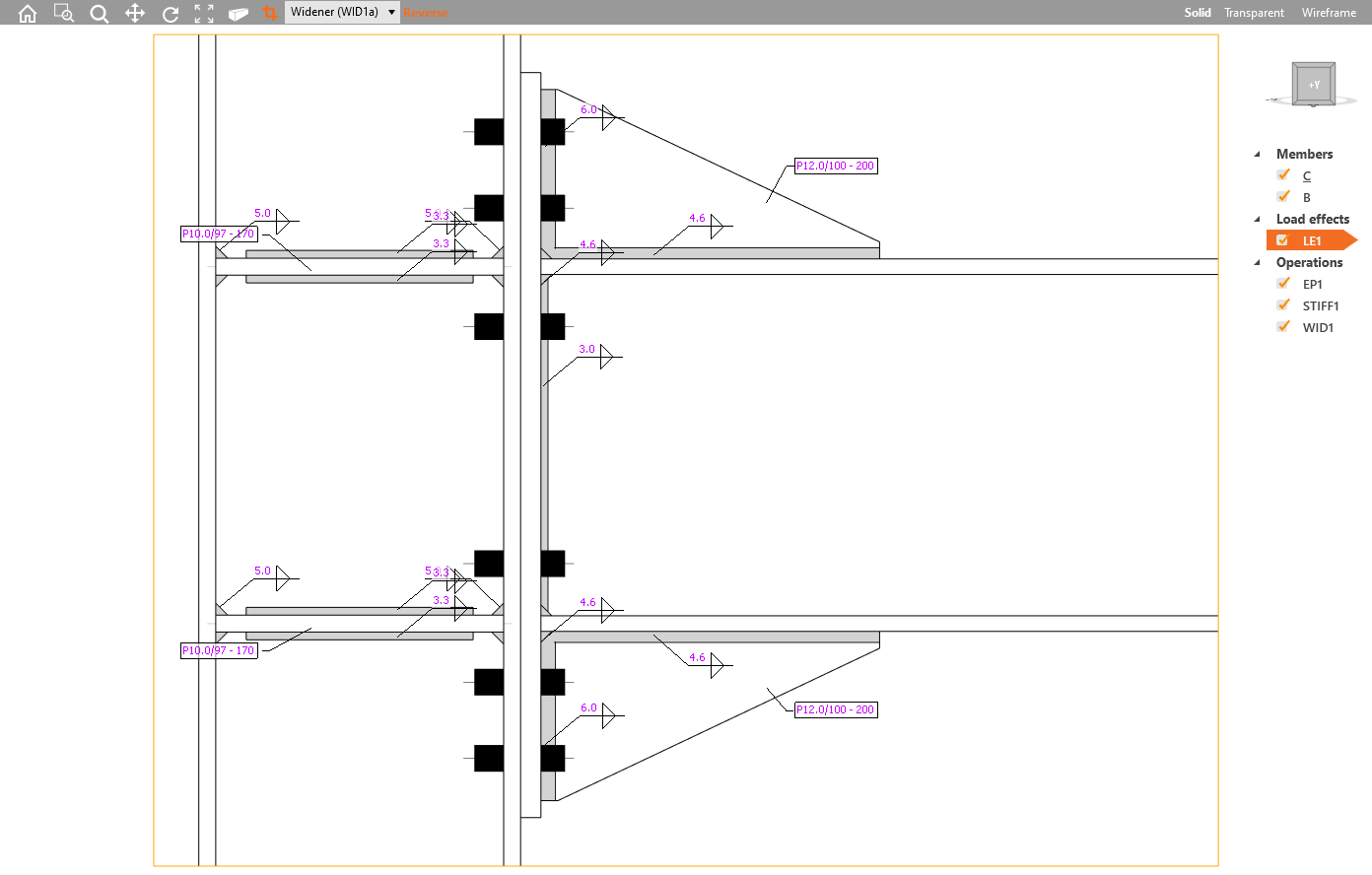
Plusieurs vues en coupe peuvent être définies, chacune d'elles doit être associée à la plaque, et les limites de la coupe ou l'orientation de la coupe peuvent être modifiées.
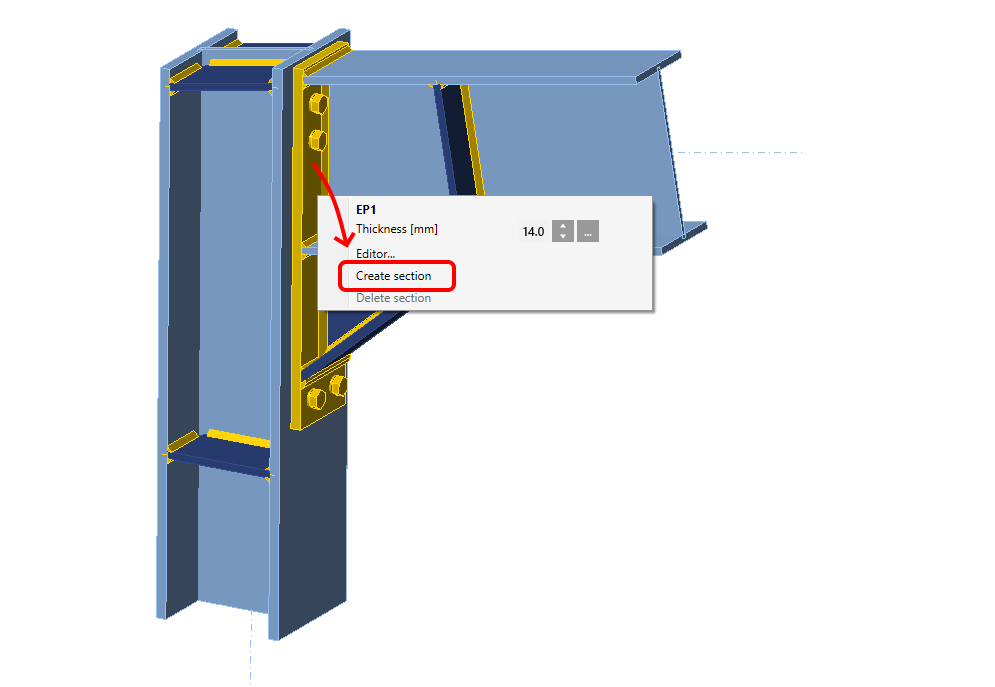
Pour ajouter une nouvelle coupe afin de produire un dessin ou un croquis, sélectionnez une plaque dans le modèle d'assemblage, puis dans le menu contextuel (clic droit) sélectionnez Créer une coupe. Pour la supprimer, sélectionnez la plaque et choisissez Supprimer la coupe.
Pour quitter la vue en coupe, cliquez sur l'icône Coupe nommée. Vous pouvez accéder à nouveau aux vues en coupe via cette icône et parcourir et modifier toutes les coupes ajoutées dans le menu.
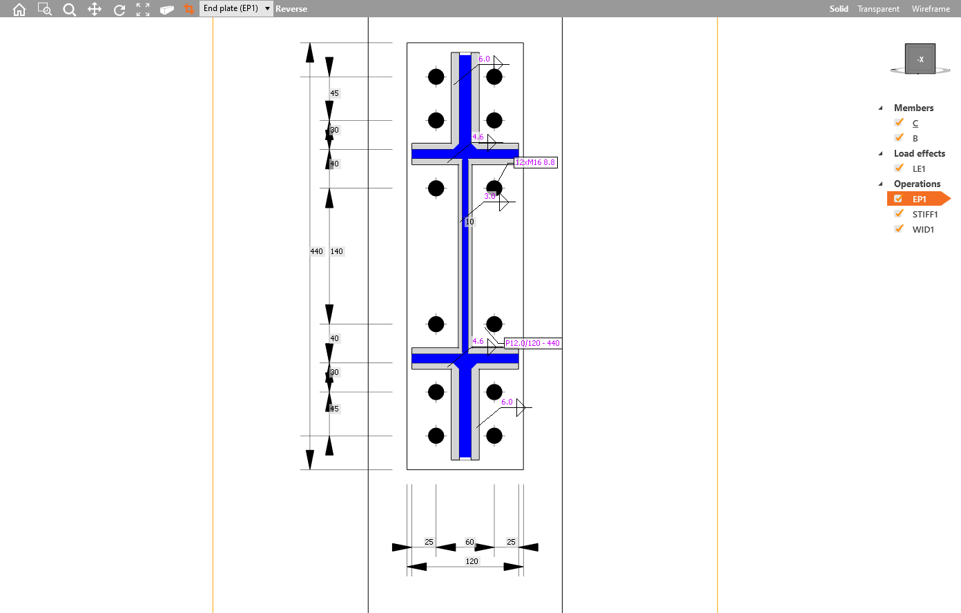
La vue du modèle de section peut être imprimée dans un rapport ou enregistrée dans une galerie pour une utilisation ultérieure.
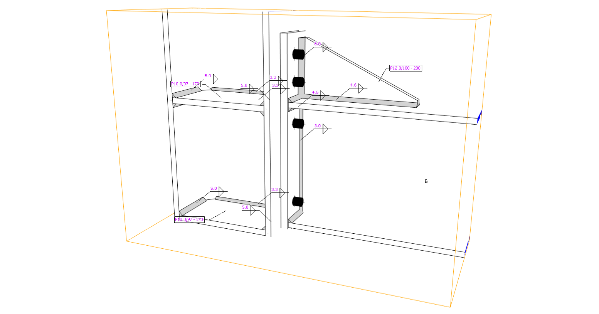
Une génération automatique d'étiquettes est définie pour les soudures et les plaques, décrivant respectivement le type et l'épaisseur de la soudure ainsi que l'épaisseur/les dimensions de la plaque.
Étiquettes de soudure et étiquette de propriété de plaque
Cette fonctionnalité est disponible uniquement dans la version Enhanced d'IDEA StatiCa Steel
110 nouveaux modèles d'assemblage dans l'assistant de démarrage
L'équipe de support d'IDEA StatiCa recueille en permanence les demandes des utilisateurs pour de nouveaux modèles. Résultat ? 110 tout nouveaux modèles d'assemblage disponibles dans l'assistant de démarrage d'IDEA StatiCa Connection. Chaque modèle peut ensuite être modifié pour atteindre les paramètres de calcul souhaités. Cela permettra aux ingénieurs du monde entier de concevoir des centaines d'assemblages répétitifs en quelques secondes et de consacrer leur temps précieux aux assemblages complexes.
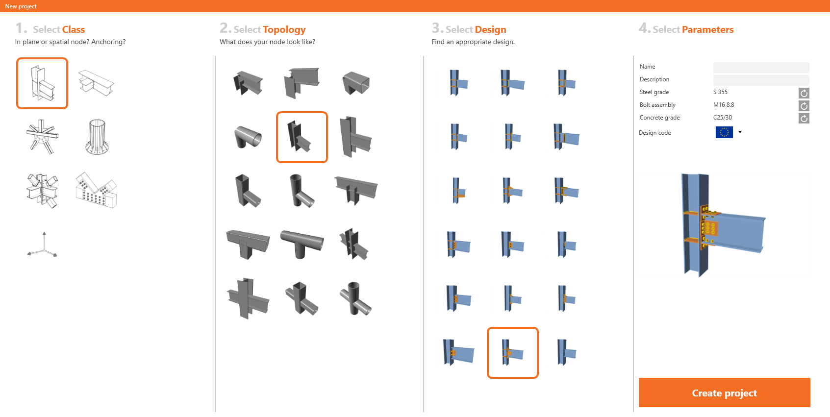
Nouveaux modèles dans l'assistant de démarrage.
Cette fonctionnalité est disponible pour la version Expert et Enhanced d'IDEA StatiCa Steel.
Assemblages bois (acier-bois)
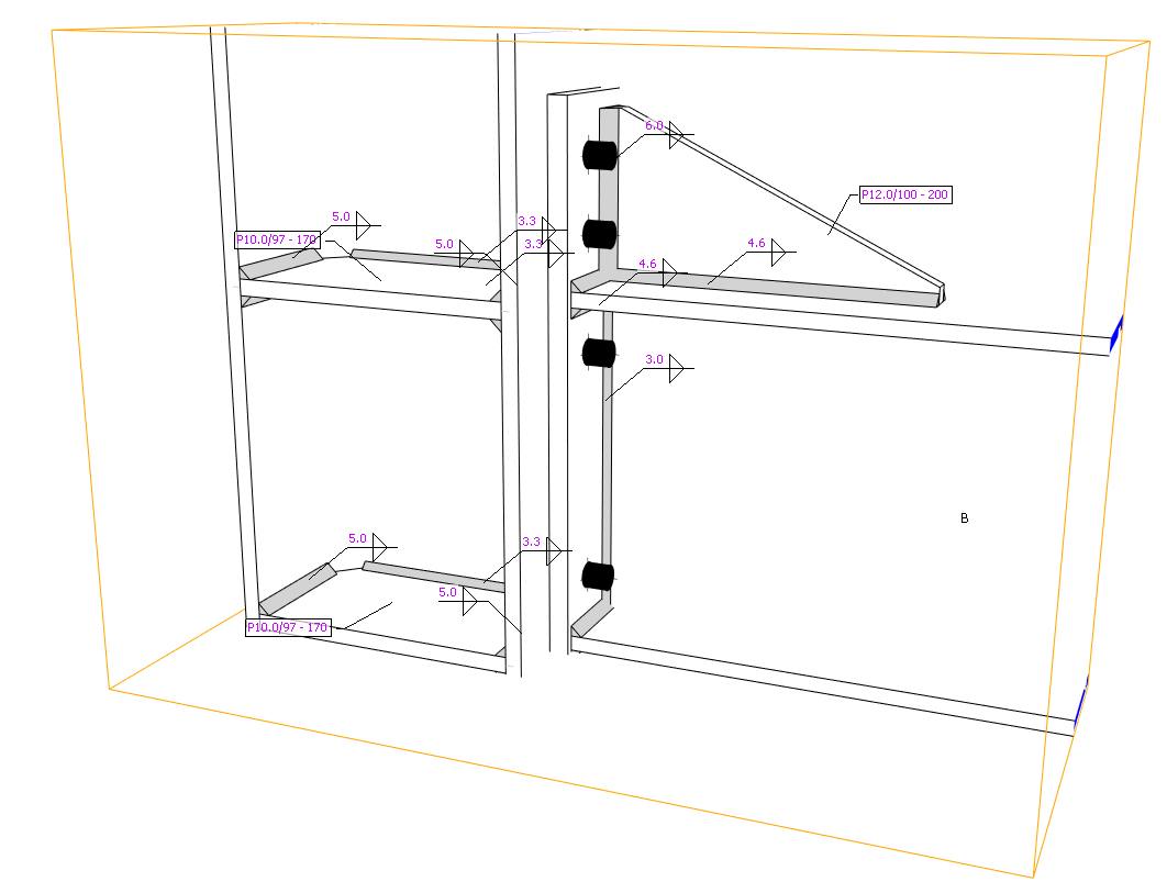
La conception des assemblages acier-bois est une nouvelle étape permettant aux utilisateurs de concevoir et de soumettre à la vérification normative différents types d'assemblages et d'éléments en plusieurs matériaux.
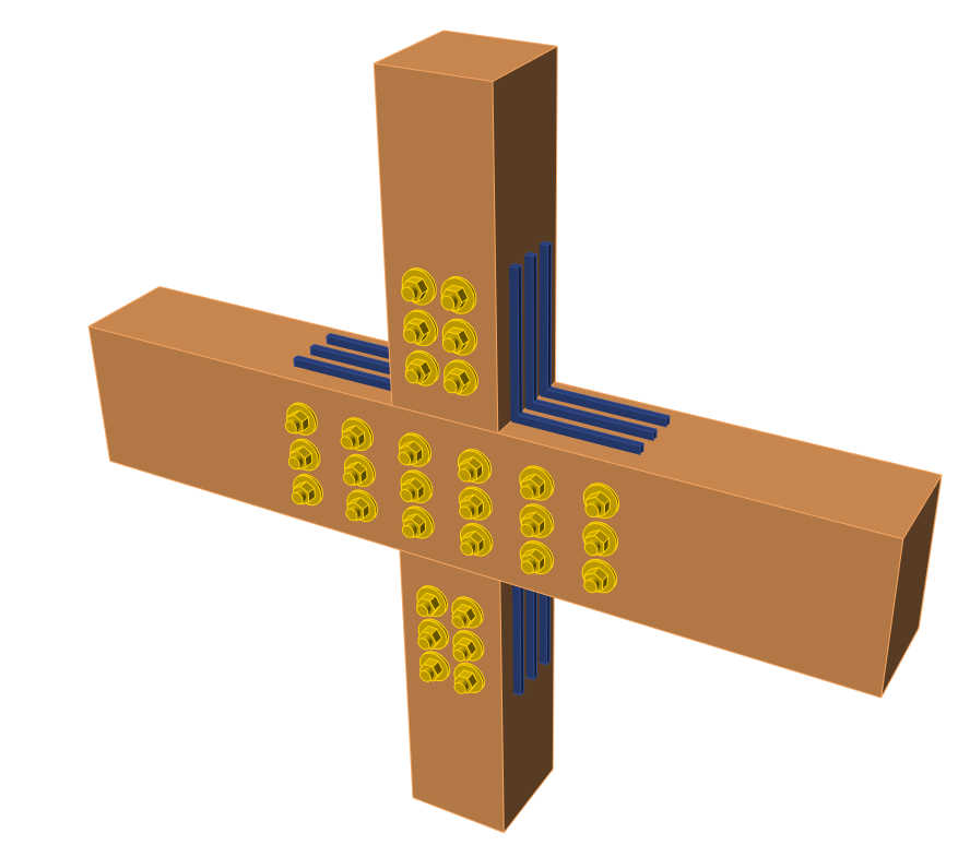
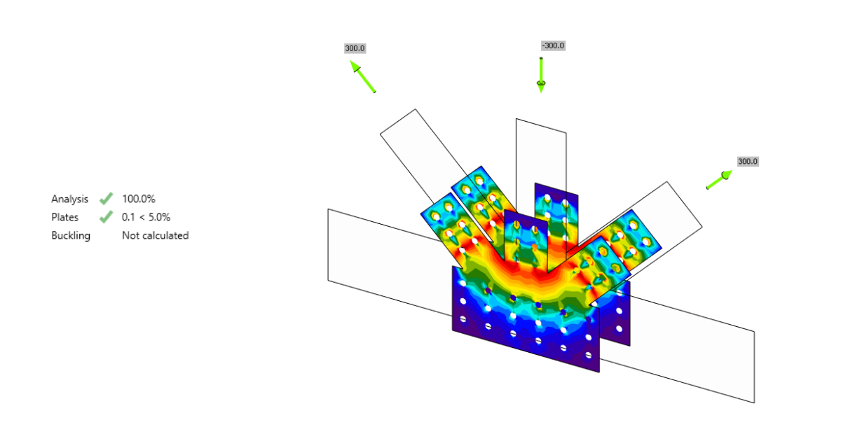
Exemple d'assemblages acier-bois
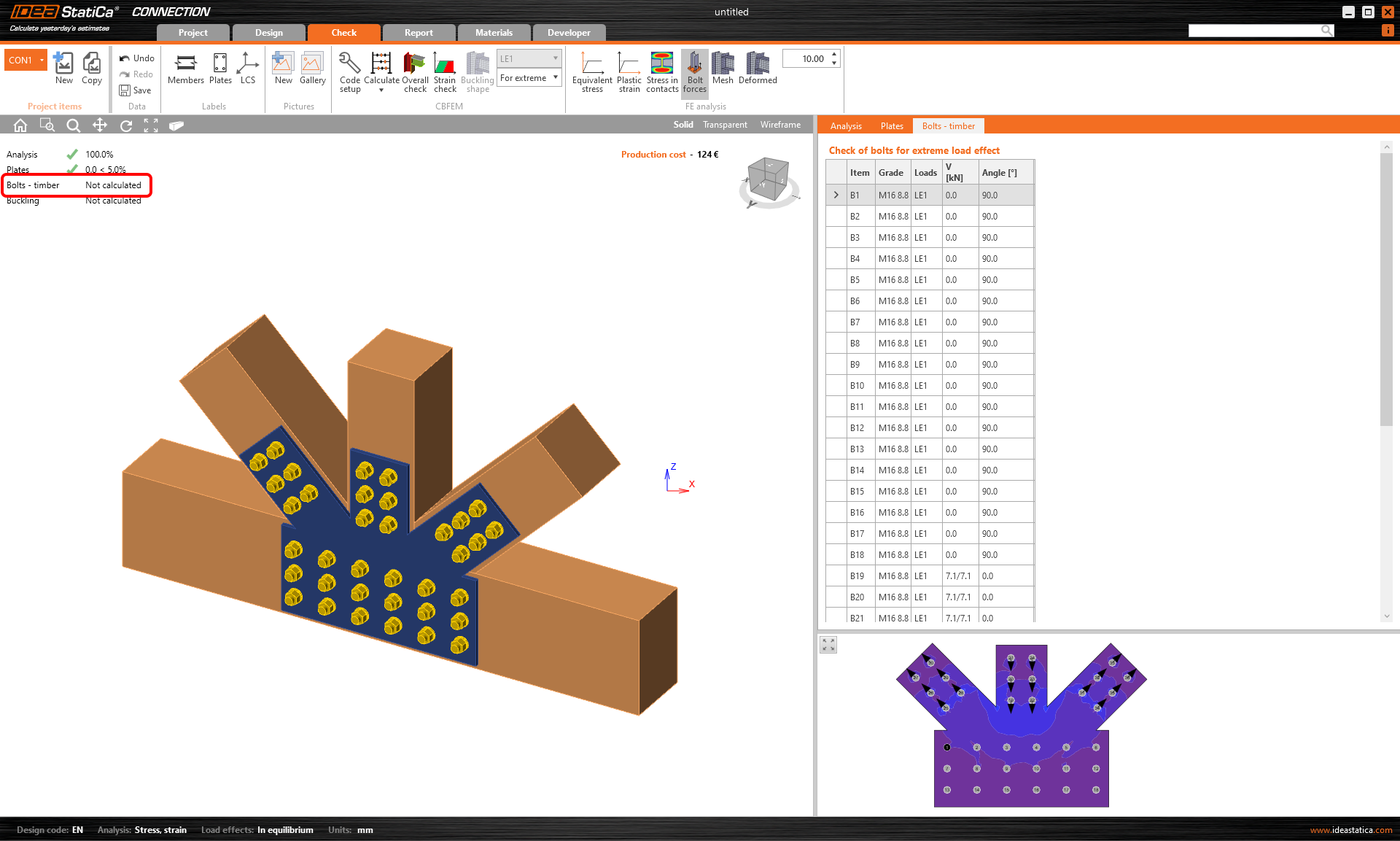
Les résultats sur les platines d'assemblage en acier peuvent être obtenus. Les vérifications normatives des platines en acier sont disponibles selon le code choisi. Les vérifications normatives des éléments en bois, des boulons et des broches ne sont pas fournies et doivent être effectuées par une application tierce. En revanche, l'application IDEA StatiCa Connection fournit les efforts de cisaillement et de traction agissant sur chaque boulon ou broche pour une vérification normative manuelle précise.
Voir également l'article de fond théorique sur les assemblages acier-bois.
Modèles et opérations de fabrication
Deux nouvelles opérations de fabrication ont été implémentées pour les éléments en bois – Gousset et Platine d'assemblage. Les utilisateurs peuvent effectuer la sélection dans le menu des opérations de fabrication.
Opérations de fabrication Gousset et Platine d'assemblage pour les éléments en bois
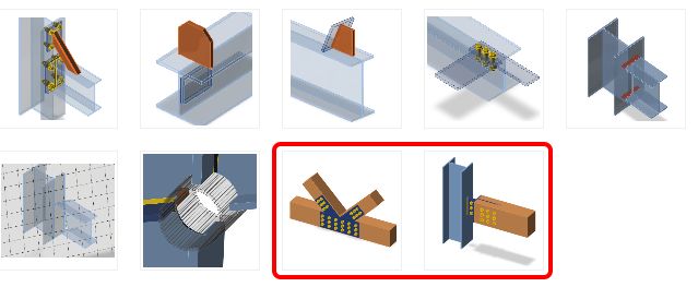
Pour vous aider dans la conception des assemblages acier-bois, de nouveaux modèles ont été ajoutés à l'assistant de l'application.
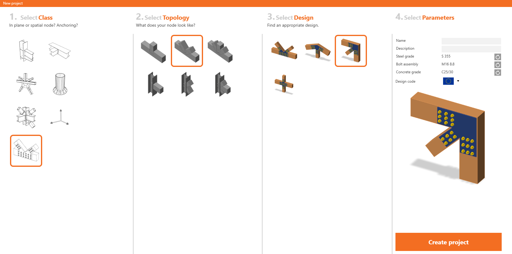
Modèles d'assemblages acier-bois
Mises à jour de la fonctionnalité
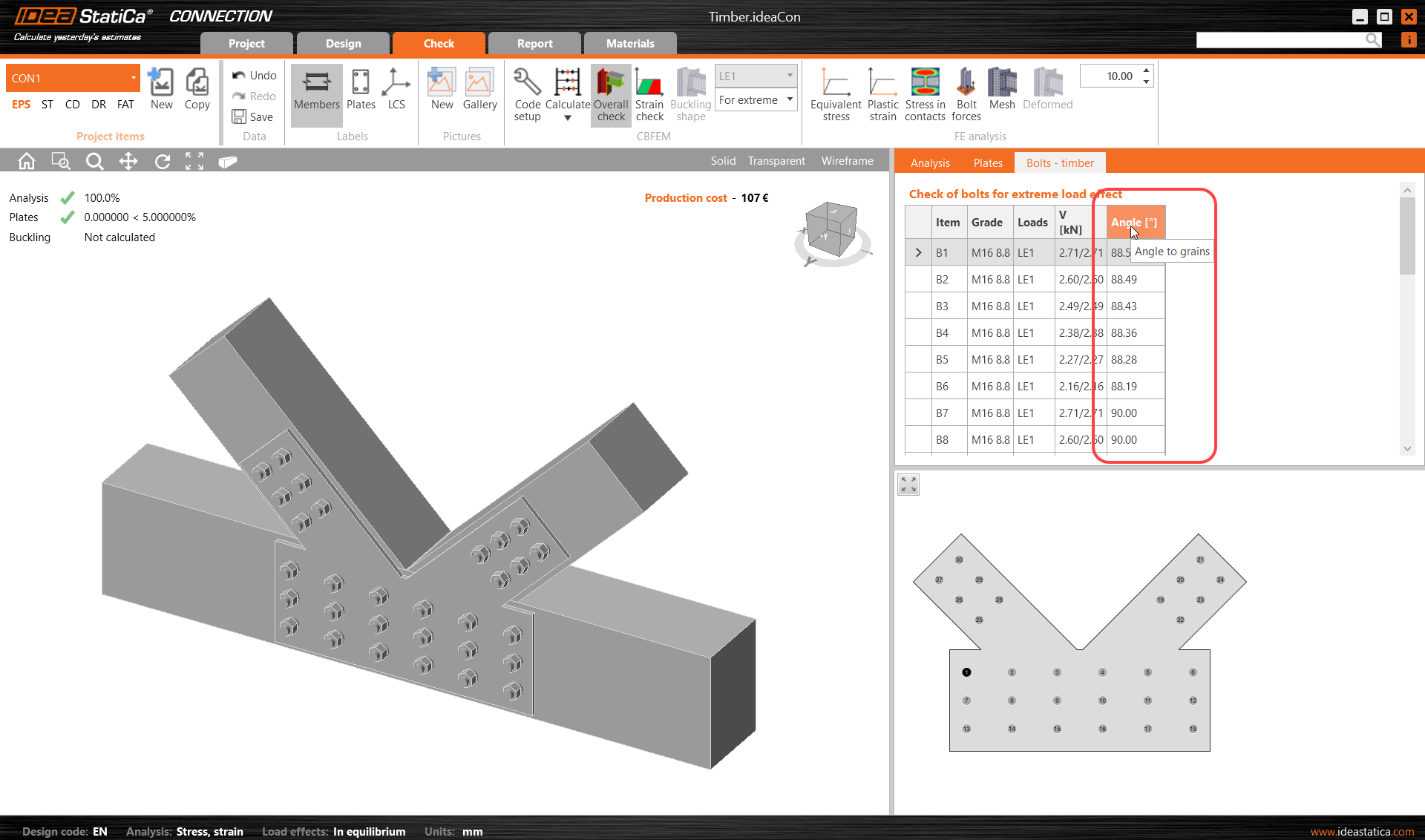
La vérification des assemblages bois a été implémentée dans la version 20.0 d'IDEA StatiCa.
Depuis le correctif 22.0.1, il est possible de visualiser l'angle de fil résultant pour la vérification des boulons. Voir l'article des Notes de version 22.1 dédié à ce sujet.
Depuis le correctif 23.0.1, un avertissement est affiché pour souligner que les boulons traversant l'élément en bois ne sont pas vérifiés (dans la scène 3D et dans le rapport).
Cette fonctionnalité est disponible pour la version Enhanced d'IDEA StatiCa Steel.
Webinaires et autres ressources
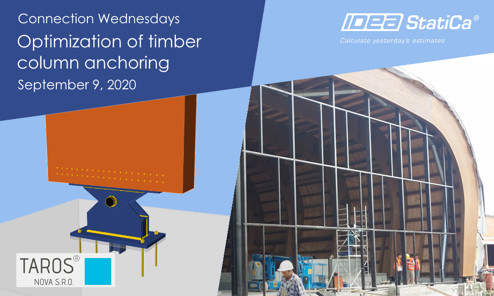
Découvrez les possibilités de la vérification des assemblages bois en pratique dans l'enregistrement du webinaire Connection Wednesdays - Optimization of timber column anchoring.
Sur notre blog, vous pouvez lire un article sur la conception des assemblages acier-bois de juillet 2020.
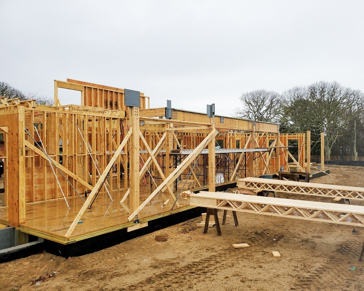
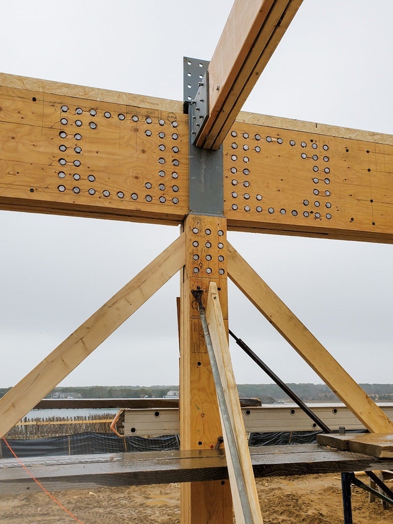
Consultez l'étude de cas d'une maison individuelle dans le Massachusetts réalisée par notre client - CRAFT Engineers.
Articles connexes
Assemblages acier-bois (Contexte théorique)
Améliorations des opérations de fabrication de cornières
Les assemblages par cornières sont populaires parmi les concepteurs et les ingénieurs en raison de leur polyvalence. Les améliorations des opérations de fabrication de cornières ouvrent de nouvelles possibilités dans la conception des assemblages et des joints. Deux platines générales perpendiculaires se coupant mutuellement peuvent être connectées par une cornière, tout comme une platine générale et une platine d'élément.
Exemples de cornières : Platine générale connectée par des cornières à un élément.
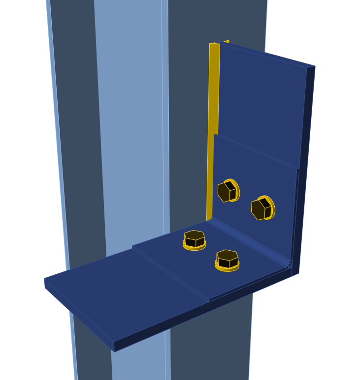
Exemples de cornières : Deux platines perpendiculaires connectées par une cornière.
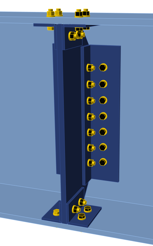
La section transversale en T peut être utilisée pour remplacer les profilés en L dans l'opération de fabrication de cornières ou pour connecter des semelles et des âmes. Grâce à cela, les types d'assemblages boulonnés (utilisés principalement aux États-Unis) peuvent désormais être conçus plus rapidement.
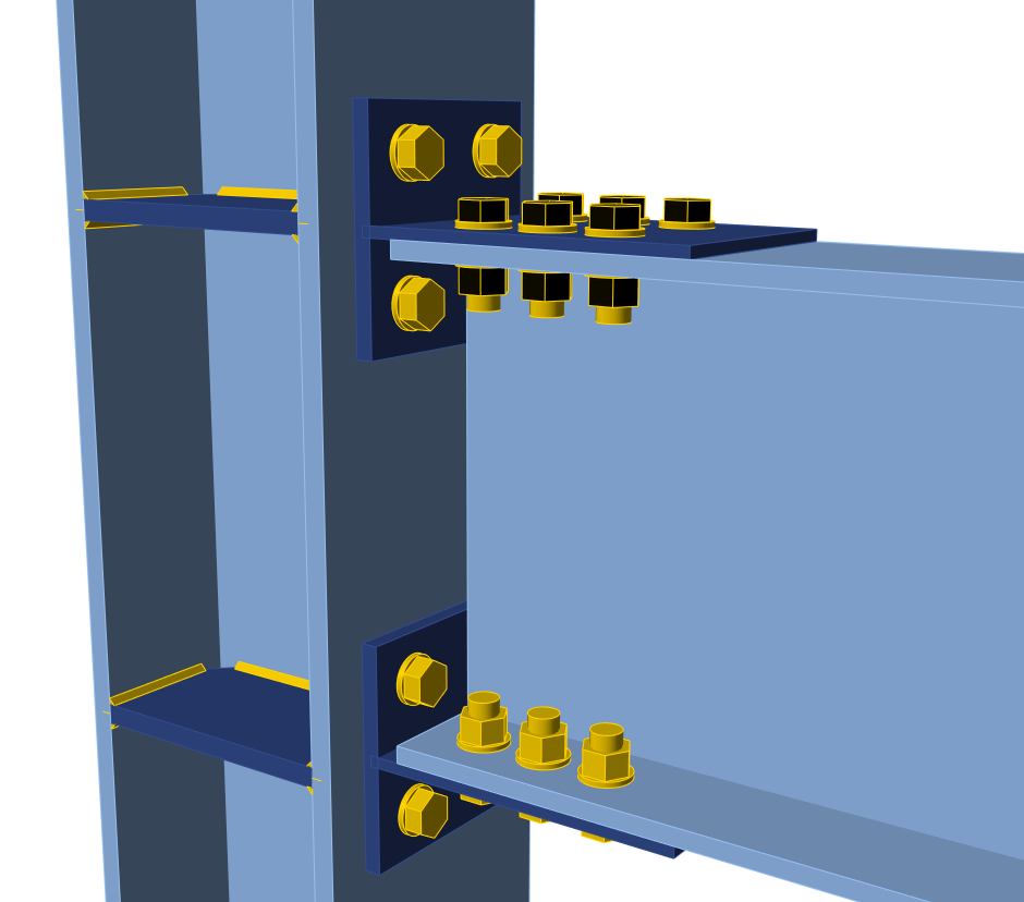
T-stub défini sur les semelles de l'élément.
Cette fonctionnalité est disponible pour la version Expert et Enhanced d'IDEA StatiCa Steel.
Entaille sur un élément
En cas de conflit entre éléments, les entailles d'ouverture devaient être définies manuellement par l'opération de fabrication Ouverture sur les semelles de l'élément. Cette situation entraînait un nombre accru d'opérations de fabrication. Désormais, la fonctionnalité Entaille peut être utilisée chaque fois qu'il est nécessaire d'éviter les conflits entre poteau-poutre ou poutre-poutre. Cette fonctionnalité est implémentée dans les opérations de fabrication Platine d'extrémité, Platine d'âme, Cornière.
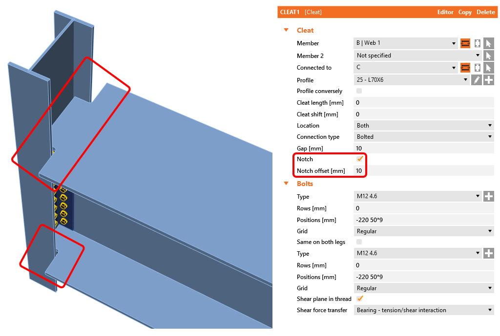
Une entaille sur les semelles définie par la nouvelle fonctionnalité.
Cette fonctionnalité est disponible pour la version Expert et Enhanced d'IDEA StatiCa Steel.
Améliorations de la vérification normative
Amélioration de la vérification normative d'ancrage EN
Dans la version précédente de IDEA StatiCa Connection, les vérifications d'ancrage étaient effectuées selon le code ETAG. À partir de la version 20, les vérifications d'ancrage sont conformes à la norme EN 1992-4 actuellement en vigueur. Cela conduit à une conception plus efficace par rapport à l'ancien ETAG.

Résultats détaillés de la vérification normative d'ancrage selon EN 1992-4.
Toutes les formules et valeurs sont fournies dans les tableaux de résultats détaillés.
Récapitulatif de la vérification d'ancrage de IDEA StatiCa Connection 20 :
| Code national | Vérification d'ancrage |
| EN | 1992-4 |
| AISC | ACI 318-14 |
| CISC | CSA A23.3-14 |
| AS | AS 5216:2018 |
| SP, GB, IS, HKG | Non effectuée |
Cette fonctionnalité est disponible pour la version Expert et Enhanced du produit IDEA StatiCa Steel.
Contrainte de contact entre deux plaques
Les contacts sont définis automatiquement lors de la définition d'un groupe de boulons ou manuellement par une opération de fabrication. Désormais, la contrainte de contact entre les deux plaques peut être affichée. Cela permet de mieux comprendre le comportement de l'assemblage et de mieux contrôler la validité du modèle (effets de levier, déformation, etc.).
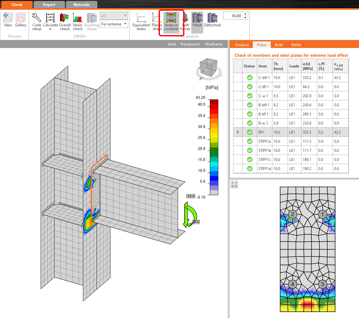
Résultats des contraintes de contact entre la platine d'extrémité et la semelle du poteau.
Les valeurs sont affichées dans le tableau de vérification des plaques. Cependant, les contraintes de contact sont uniquement informatives et ne sont pas utilisées dans aucune vérification. De plus, la contrainte dans l'épaisseur des éléments coques n'est pas prise en compte.
Cette fonctionnalité est disponible pour la version Expert et Enhanced d'IDEA StatiCa Steel.
Platine de base partiellement appuyée
L'ancrage des assemblages acier est désormais encore plus polyvalent, avec la possibilité d'appuyer partiellement la platine de base ou l'élément.


Ancrage général de l'élément avec un bloc de fondation en béton partiellement appuyé défini.
Cette fonctionnalité est disponible pour la version Expert et Enhanced du produit IDEA StatiCa Steel.
Favoris de la bibliothèque de sections transversales
Les bases de données de la bibliothèque de sections transversales contiennent des sections types pour huit codes de calcul nationaux, avec un total de plus de mille éléments. Cela représente de nombreuses possibilités pour le dimensionnement. Mais cela peut aussi rendre le processus de recherche et de sélection de la section transversale souhaitée fastidieux, en particulier pour la conception répétitive d'assemblages. À partir de la version 20, l'utilisateur peut facilement marquer la famille de sections transversales souhaitée comme favorite et la faire afficher séparément du reste de la base de données. Cela accélère considérablement le processus de dimensionnement.
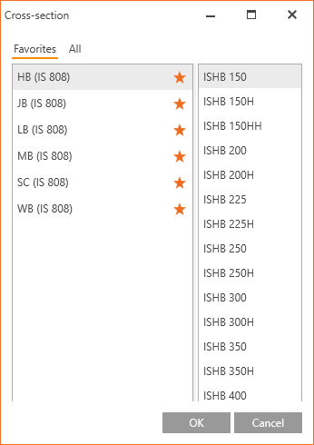
Sections transversales favorites définies par l'utilisateur.
Cette fonctionnalité est disponible pour la version Expert et Enhanced du produit IDEA StatiCa Steel.
Ordre des éléments basé sur la région dans la bibliothèque de sections transversales
IDEA StatiCa réorganise automatiquement l'ordre des éléments de section transversale en fonction du code de calcul sélectionné lors du lancement de IDEA StatiCa Connection. Grâce à cette fonctionnalité, par exemple, les ingénieurs des États-Unis utilisant le code AISC auront les sections transversales pertinentes selon l'AISC dans les premières lignes de la bibliothèque. Ces paramètres peuvent être définis individuellement par tous les utilisateurs au sein de l'organisation afin d'accélérer le travail de chaque ingénieur.
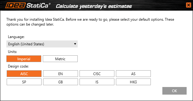
Options de préférences utilisateur disponibles lors du premier démarrage de IDEA StatiCa Connection.
Cette fonctionnalité est disponible pour la version Expert et Enhanced d'IDEA StatiCa Steel.
Sections transversales taïwanaises typiques
Les sections transversales taïwanaises typiques ont été intégrées dans la bibliothèque de sections transversales. Les sections transversales UC, L-angle, CHS et RHS avec le marqueur (TW) sont désormais disponibles dans la bibliothèque de sections transversales.+
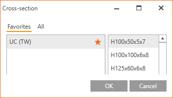
Section transversale UC Taïwan dans la bibliothèque.
Cette fonctionnalité est disponible pour la version Expert et Enhanced du produit IDEA StatiCa Steel.
Code de calcul indien (IS)
Le code de calcul indien pour les assemblages acier-acier (IS) est désormais disponible aux côtés de sept autres normes de calcul. Les composants boulons, boulons précontraints, soudures et béton en compression sont vérifiés conformément à IS 800:2007 et IS 456:2000, y compris les dispositions constructives.
Les nuances d'acier, les classes de boulons et les sections transversales en acier courantes sont répertoriées dans la bibliothèque.
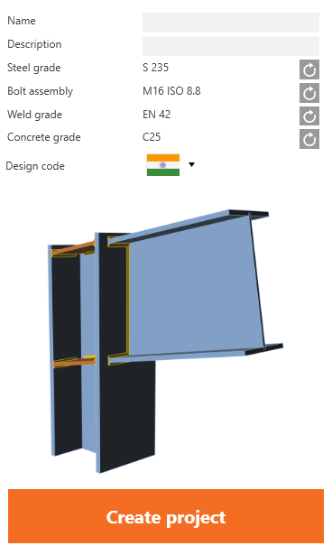
Code indien et sections transversales courantes
Cette fonctionnalité est disponible pour la version Expert et Enhanced d'IDEA StatiCa Steel.
IDEA StatiCa Code-check manager
Interface graphique unifiée pour CAO et EF
L'interface utilisateur de l'application IDEA StatiCa est la clé d'un flux de travail quotidien fluide. Désormais, l'interface utilisateur du gestionnaire de vérification normative est unifiée pour les applications CAO et EF, et elle peut être utilisée pour exporter, gérer, recalculer ou synchroniser tous les éléments d'assemblage ou les éléments de structure.
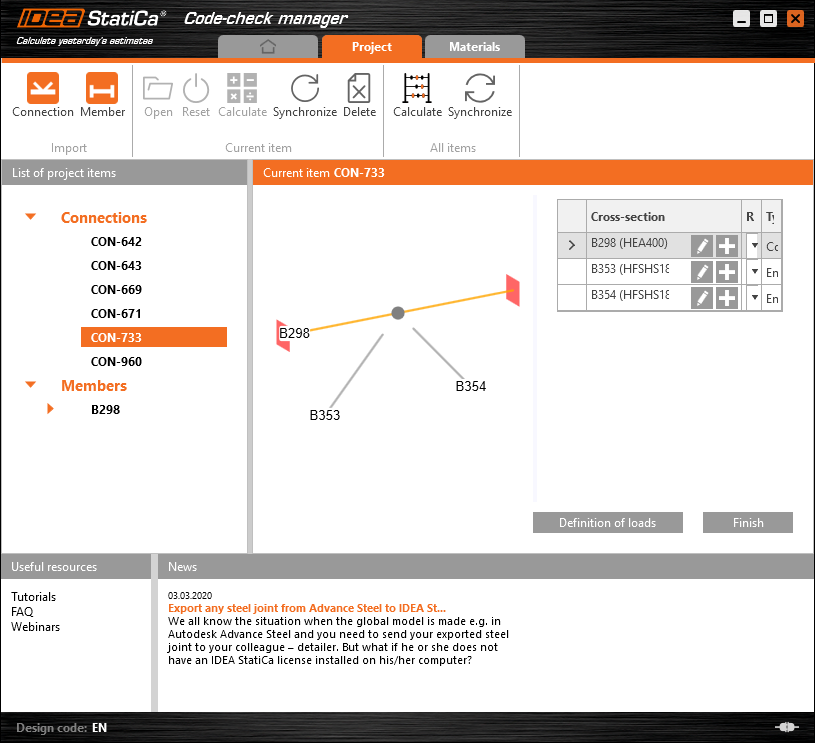
Application du gestionnaire de vérification normative.
Tekla Structures, Advance Steel et Revit
Tous les liens CAO sont désormais alimentés par la même technologie, ce qui nous permet d'améliorer les fonctionnalités en une seule mise à jour pour toutes les applications CAO. Dans IDEA StatiCa 20, une toute nouvelle méthode d'importation des poutres à section transversale asymétrique, telles que les profils en L, en U, etc., a été mise en œuvre. Désormais, le positionnement de la section transversale est importé exactement tel qu'il est défini dans l'application CAO, sans modification supplémentaire.
Sélection multiple et export depuis un logiciel EF
L'import depuis les applications EF est désormais plus simple que jamais : l'utilisateur peut sélectionner plusieurs nœuds, et le gestionnaire de vérification normative les importera tous en tant qu'assemblages uniques. IDEA StatiCa s'intègre automatiquement à votre logiciel lors de l'installation, en ajoutant une nouvelle commande au ruban.
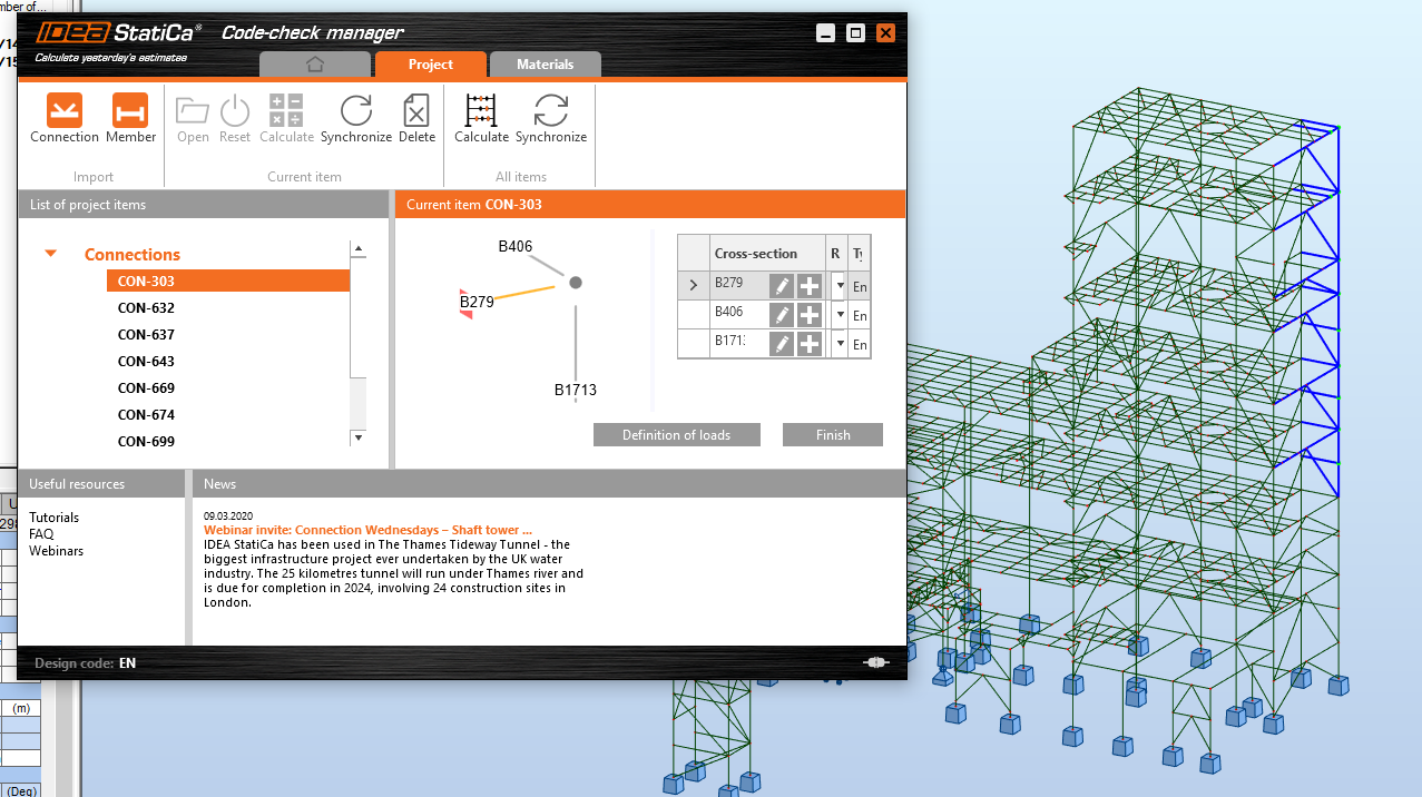
En exécutant cette commande, ouvrez le gestionnaire de vérification normative. Faites glisser la souris pour sélectionner en masse les nœuds souhaités et cliquez sur le bouton Connection pour importer toutes les données en une seule fois. Après avoir ouvert et conçu les assemblages importés un par un, vous pouvez lancer l'analyse en masse pour effectuer la vérification normative de tous les assemblages en une seule fois.
Profitez de la fonction de synchronisation : si vous modifiez quoi que ce soit (par exemple une combinaison de charges, la section transversale d'un élément) dans le modèle structurel, en un seul clic vous téléchargez les nouvelles données vers tous les assemblages de la liste tout en conservant le dimensionnement. Cliquez ensuite sur « Tout calculer » pour vérifier les vérifications normatives des modèles d'assemblages actualisés.
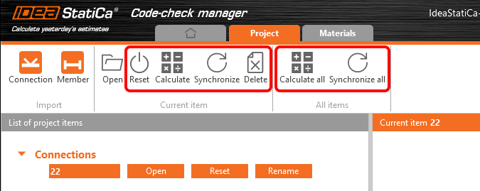
Cette fonctionnalité est disponible dans tout package IDEA StatiCa Steel. Le calcul en masse et la synchronisation de tous les éléments listés sont disponibles uniquement dans le package Enhanced IDEA StatiCa Steel.
Veuillez noter que pour SCIA Engineer, le gestionnaire de vérification normative n'a pas encore été implémenté et le lien BIM importe les nœuds individuels un par un uniquement.
IDEA StatiCa Member BETA
La version BETA de IDEA StatiCa a été un succès ! Elle est instantanément devenue l'une des applications IDEA StatiCa les plus lancées. Sur la base des retours des utilisateurs, nous avons amélioré diverses fonctionnalités de l'interface graphique et de vérification normative.
En collaboration avec les équipes universitaires, nous avons achevé la majorité des travaux de vérification et de validation. Les analyses MNA et LBA de IDEA StatiCa Member ont été correctement testées dans de multiples expériences et exemples. La vérification et la validation de l'analyse GMNIA pour les éléments à section laminée à chaud ont également été testées. Cependant, nous devons admettre que le processus de vérification est extrêmement laborieux, et le travail pour les éléments à section soudée est encore en cours.
IDEA StatiCa 20 apporte une version améliorée de IDEA StatiCa Member afin que les ingénieurs structure puissent gérer correctement les problèmes de flambement et de stabilité dans des projets acier de complexité variable.
Pour faciliter les flux de travail, nous avons mis en place des liens BIM avec plusieurs applications EF – SAP 2000, ETABS, Autodesk Robot Structural Analysis, RFEM/RSTAB et AxisVM.
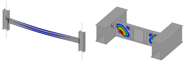
Flambement global et local simulés dans IDEA StatiCa Member BETA
IDEA StatiCa Member est automatiquement disponible pour tous les utilisateurs disposant d'une licence IDEA StatiCa Steel, édition Enhanced. Plus d'informations, des tutoriels, des exemples de projets et bien plus encore sont disponibles sur nos pages Acier.
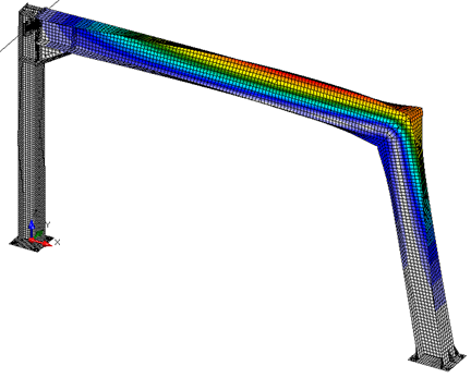
Flambement d'un portique dans IDEA StatiCa Member BETA
Les opérations de fabrication dans la version précédente de l'application Member étaient limitées. Désormais, le plein potentiel de conception est offert avec cinq nouvelles opérations de fabrication telles que la coupe d'un élément, la coupe d'une plaque, l'élément de raidissement, la soudure générale et le raidisseur transversal.
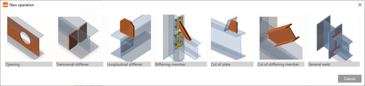
Opérations de fabrication de IDEA StatiCa Member.