Notes de version IDEA StatiCa Concrete 20.1
Introduction
La nouvelle version d'IDEA StatiCa est disponible ! Nous apportons une nouvelle série de fonctionnalités et d'améliorations pour optimiser la conception de vos projets en béton. Quelle que soit la complexité de votre projet en béton, IDEA StatiCa offre :
- Des vérifications normatives complètes
- Des types d'analyses avancées
- Une topologie illimitée des sections transversales et des dispositions de ferraillage
- Tous les détails 2D en béton
- Des rapports qui permettent de mener le projet à terme
Nos utilisateurs réalisent actuellement ces tâches via des applications distinctes - Detail, RCS et Beam. Nous sommes ravis de vous présenter une toute nouvelle application dans IDEA StatiCa Concrete - Member. Elle unifiera toutes les conceptions et vérifications normatives de tous les éléments en béton armé en un seul endroit, intégrée dans votre logiciel EF. Member sera disponible en version BÊTA pour tous les utilisateurs disposant d'une licence béton d'IDEA StatiCa.
En plus de cette toute nouvelle application, vous trouverez des améliorations dans nos moteurs de vérification normative :
- Zones partiellement chargées
- Vérification à la fatigue
Par ailleurs, nous avons préparé quelques améliorations concernant la gestion des licences IDEA StatiCa pour vous permettre une gestion flexible et confortable de vos licences.
Nous espérons que vous apprécierez toutes nos nouvelles fonctionnalités et améliorations et serions ravis de recevoir vos commentaires à tout moment.
Calculez les estimations d'hier !
Élément en béton BETA
La version 20.1 introduit une nouvelle application pour le calcul du béton - Concrete Member BETA. Modélisez, ferraillez et effectuez la vérification normative d'un élément en béton critique en quelques minutes.
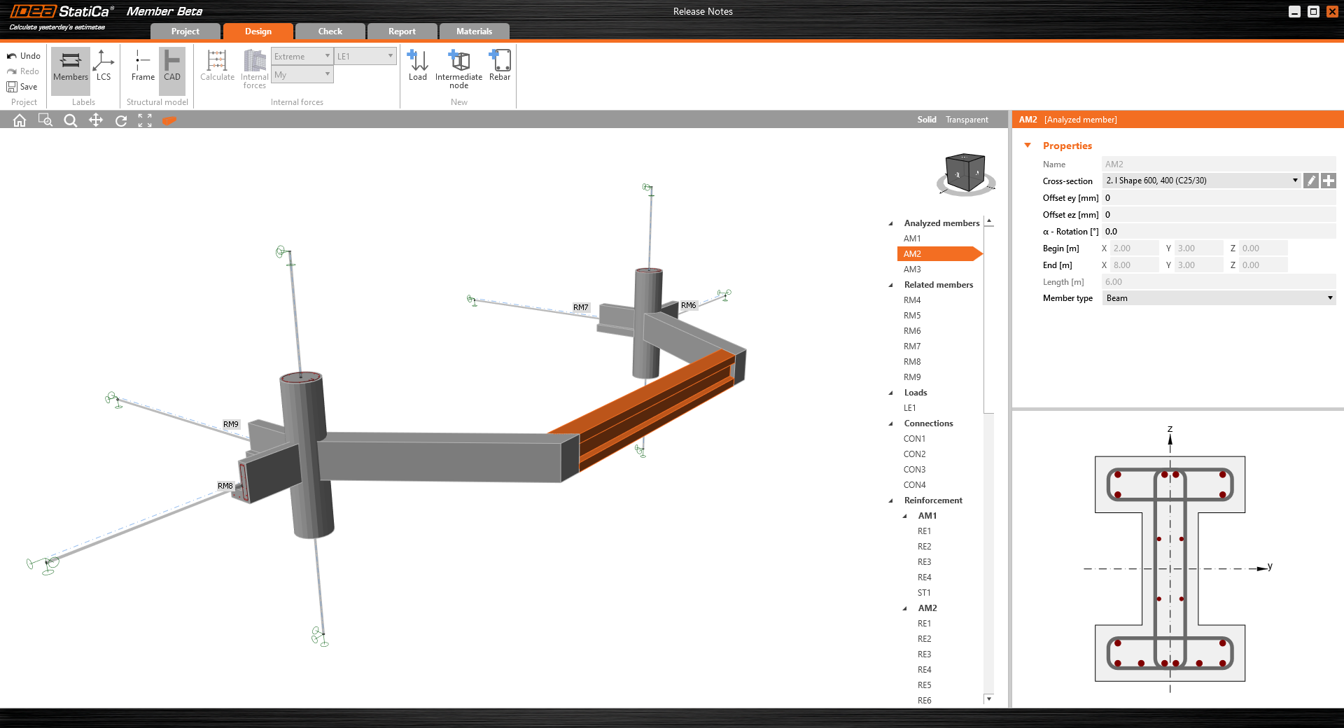
Géométrie
Grâce à notre nouvelle application, l'utilisateur peut facilement concevoir et évaluer des structures en béton armé spatiales composées d'éléments 1-D, de poutres et de poteaux. À l'avenir, il sera possible d'analyser des éléments structurels 3-D de toute topologie.
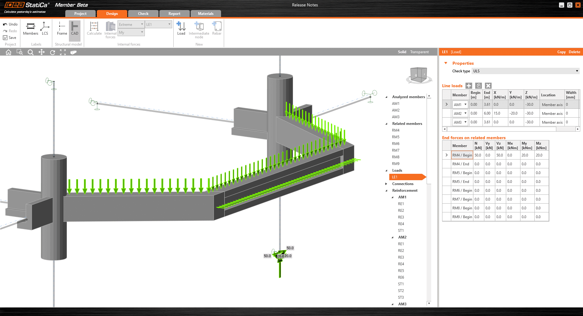
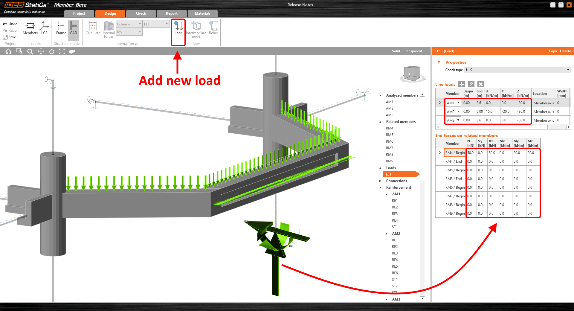
Chargement
La charge peut être appliquée dans la direction de n'importe quel axe d'élément via la charge linéaire. Les extrémités des éléments concernés peuvent être soumises à des forces ponctuelles (et des moments) représentant les forces nodales obtenues à partir de l'analyse globale.
Ferraillage
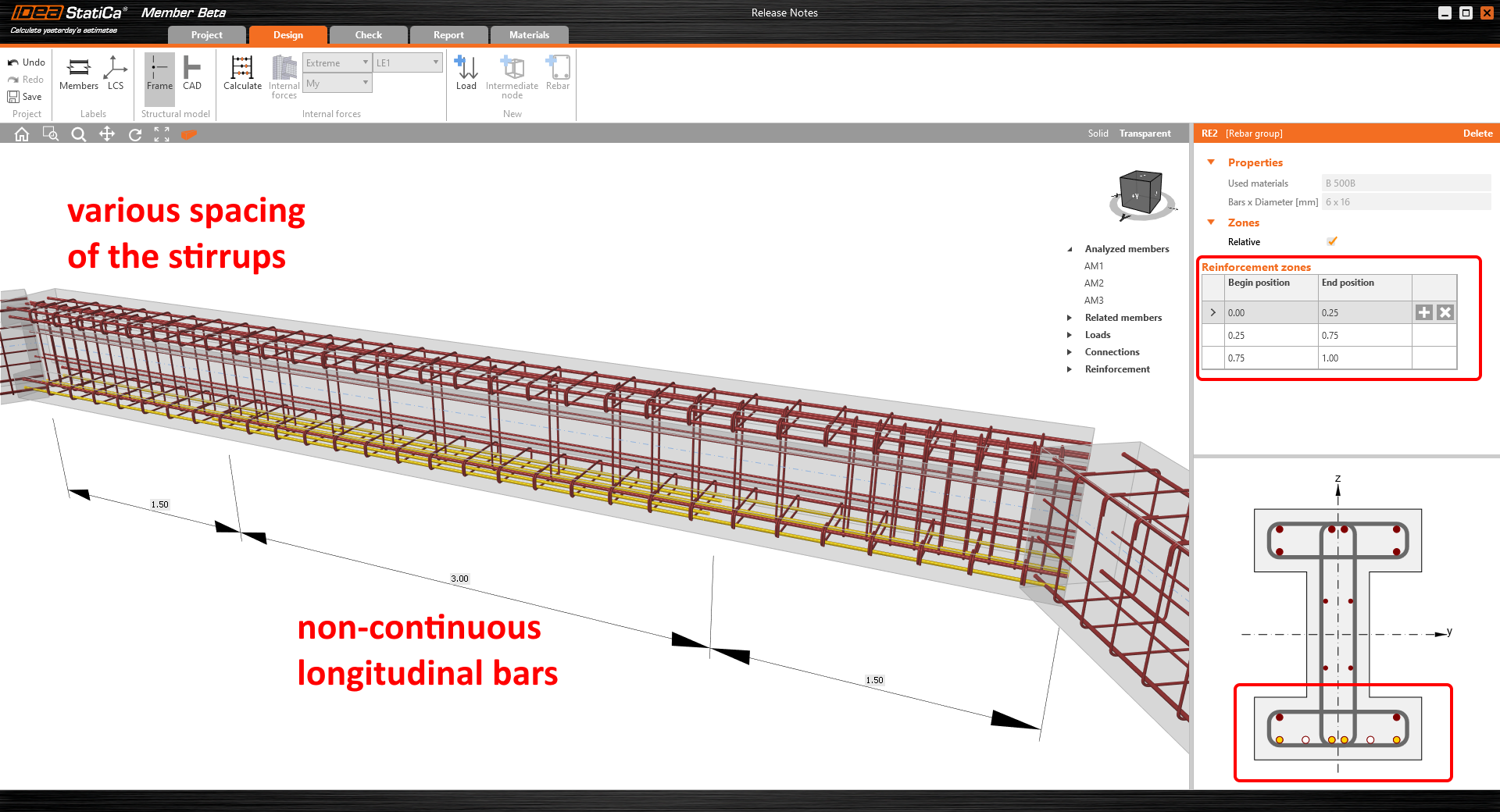
À l'aide de notre boîte de dialogue bien connue, l'utilisateur peut concevoir le ferraillage longitudinal et les étriers dans chaque élément. Les modèles prédéfinis peuvent accélérer l'ensemble du processus de conception du ferraillage. Chaque groupe de ferraillage longitudinal, ainsi que les étriers, peuvent être facilement modifiés dans la fenêtre Propriétés.
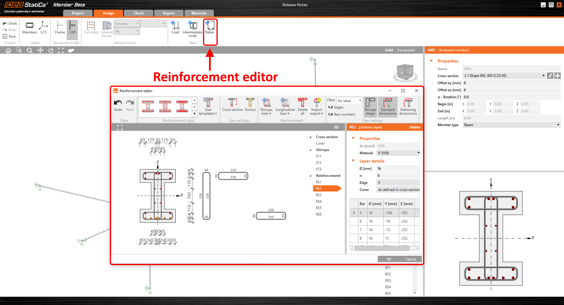
Vous pouvez définir plusieurs zones de ferraillage sur la longueur de l'élément et créer une disposition de ferraillage complexe incluant différents espacements des étriers et des longueurs de barres de ferraillage longitudinales.
Analyse
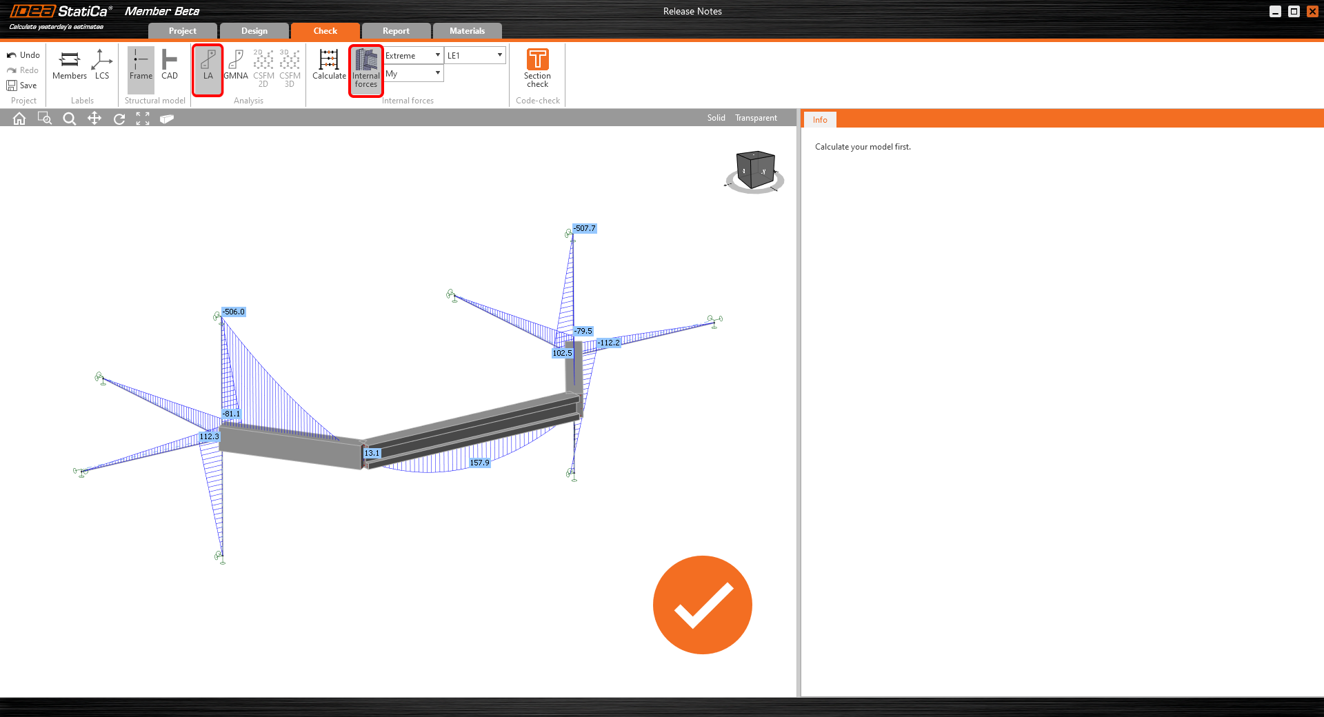
Plusieurs types d'analyse différents seront disponibles pour un même modèle structurel. Actuellement, seule l'analyse linéaire peut être effectuée, mais d'autres types d'analyse seront implémentés dans les versions suivantes.
Quatre types d'analyses seront disponibles pour analyser les éléments en béton. Actuellement, une analyse linéaire peut être exécutée dans Concrete Member Beta, les trois autres types d'analyses sont en cours de développement ou en phase de finalisation.
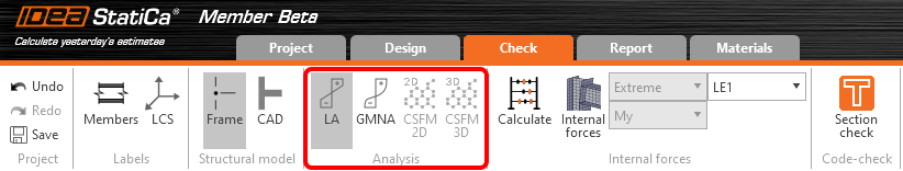
- Analyse linéaire (LA) : implémentée dans Concrete Member Beta
- Analyse non linéaire géométrique et matérielle, incluant l'analyse thermique (GMNA) : en cours de développement
- Méthode du Champ de Contraintes Compatible 2D (CSFM 2D) : développée/en amélioration (CSFM est disponible dans IDEA StatiCa Detail)
- Méthode du Champ de Contraintes Compatible 3D (CSFM 3D) : en cours de développement
Vérification de section
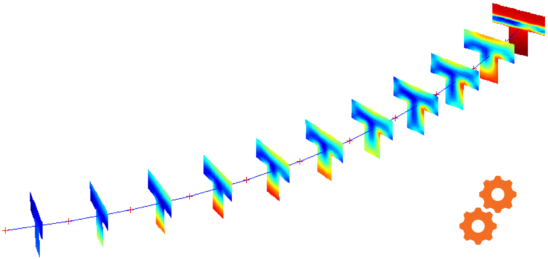
Après l'analyse linéaire, l'utilisateur peut effectuer une vérification détaillée de section à l'aide de l'application RCS, qui sélectionne automatiquement les sections les plus sollicitées sur les éléments analysés et les vérifie.

Disponible dans les éditions Expert et Enhanced .
IDEA StatiCa Detail
Aires partiellement chargées
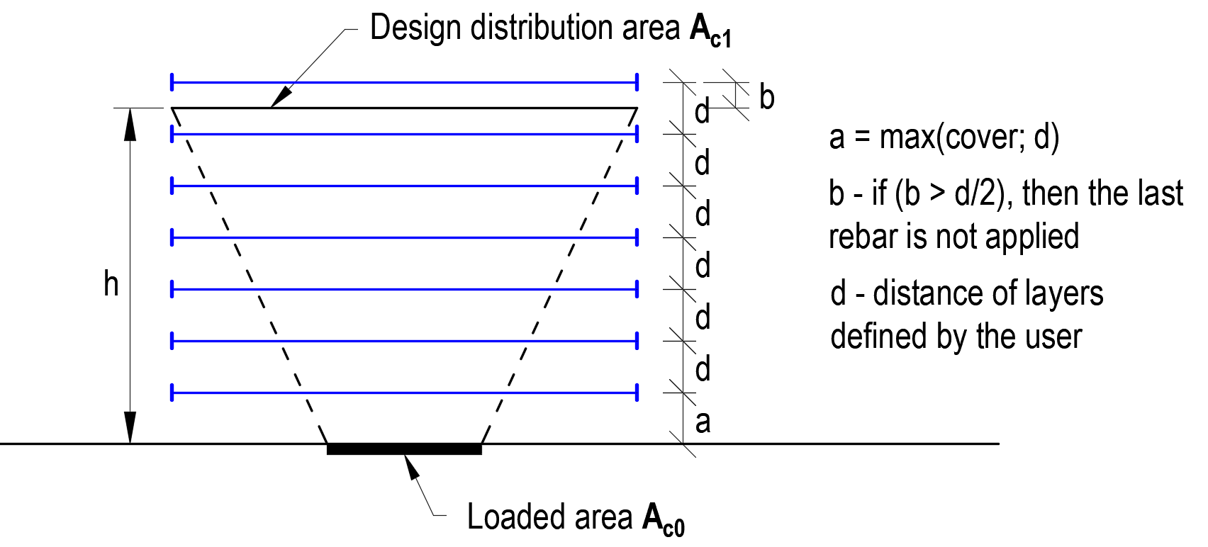
Ferraillage dans les Aires Partiellement Chargées
Vous pouvez concevoir le ferraillage dans l'aire partiellement chargée de manière plus efficace depuis la version 20.1. Les barres de ferraillage font partie du modèle CSFM, et l'adhérence entre le béton et les barres est considérée comme parfaite.
À propos des Aires Partiellement Chargées
Cette fonctionnalité est principalement destinée aux ingénieurs structure spécialisés dans le préfabriqué et les ouvrages d'art, qui traitent des réactions importantes au niveau des appuis ou des forces de précontrainte concentrées issues des câbles de précontrainte dans les poutres. L'avantage réside dans un dimensionnement non conservateur, permettant des économies de matériaux et de coûts.
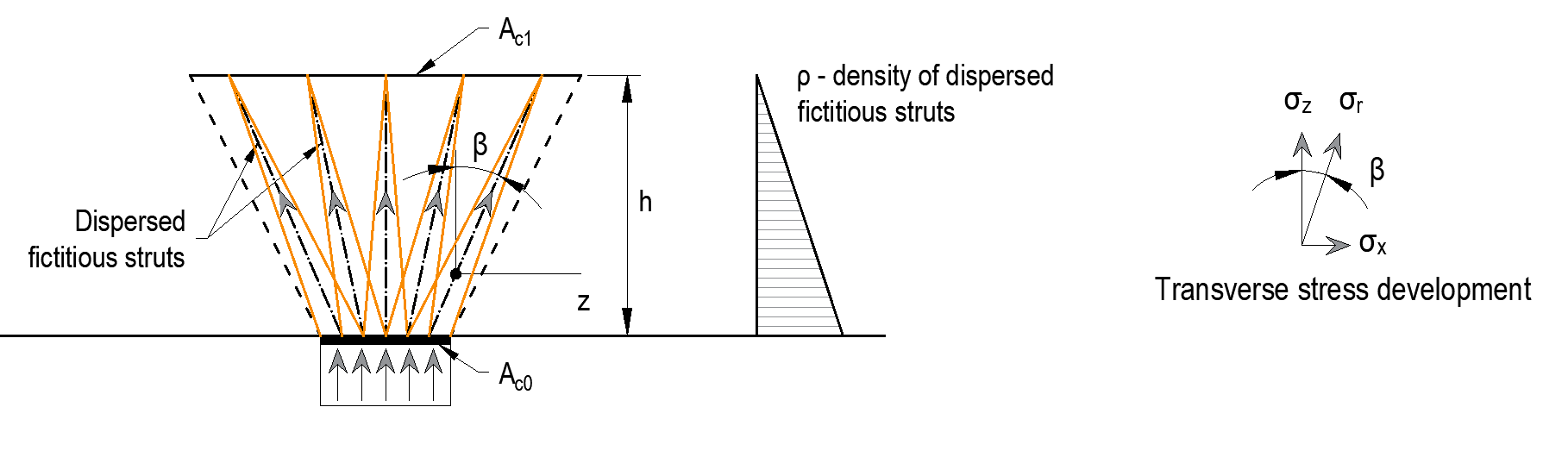
Nous avons trouvé comment traiter l'état de contrainte triaxial dans les aires partiellement chargées. Dans ces zones, l'écrasement du béton est admis, et la résistance du béton en compression peut être augmentée grâce au confinement transversal conformément aux normes en vigueur (Eurocode). L'augmentation de la résistance peut atteindre 3 fois la résistance cylindrique du béton.

L'aire partiellement chargée se rencontre dans toute structure. Parmi les exemples typiques, on peut citer les entretoises de ponts avec une zone au-dessus des appuis, les zones sous ancrage, ou une charge concentrée sur le bord d'un voile. Les aires partiellement chargées sont dimensionnées conformément aux exigences de l'Eurocode et sont simultanément limitées par la géométrie du modèle (ouvertures, épaisseur, bords, changement brusque de section transversale).

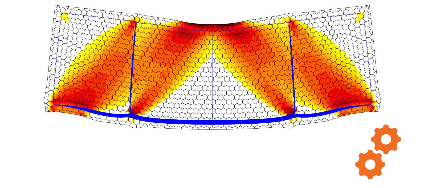
L'augmentation de la résistance du béton peut être prise en compte si le confinement est assuré. En raison de cette condition, des barres de ferraillage sont automatiquement ajoutées pour satisfaire la condition relative au confinement et aux dispositions de l'Eurocode.

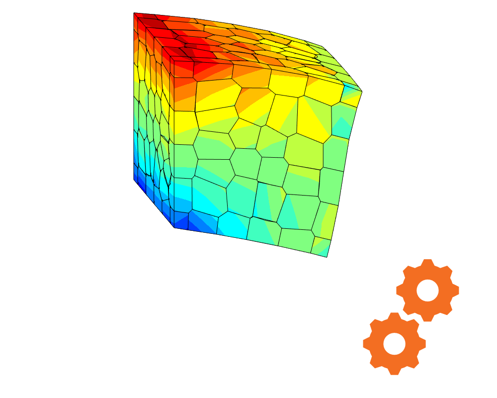
Cette fonctionnalité garantit que les modèles convergent tout en satisfaisant aux critères de dimensionnement des normes en vigueur (Eurocode). La méthode implémentée est indépendante du maillage en éléments finis. La capacité portante est augmentée avec le changement de l'aire de béton. La conséquence de cet état est une contrainte constante sur toute la hauteur d'un cône. Des bielles fictives dispersées influencent artificiellement la rigidité du cône et redistribuent correctement la contrainte transversale qui apparaît dans cette zone. La densité de chaque bielle dispersée augmente dans la direction de la charge appliquée.
Les limitations connues découlent des normes en vigueur dans l'Eurocode.
- Les cônes ne peuvent pas se chevaucher
- Les aires Ac1 et Ac0 se trouvent sur la résultante de la force appliquée
IDEA StatiCa RCS
Vérification à la fatigue
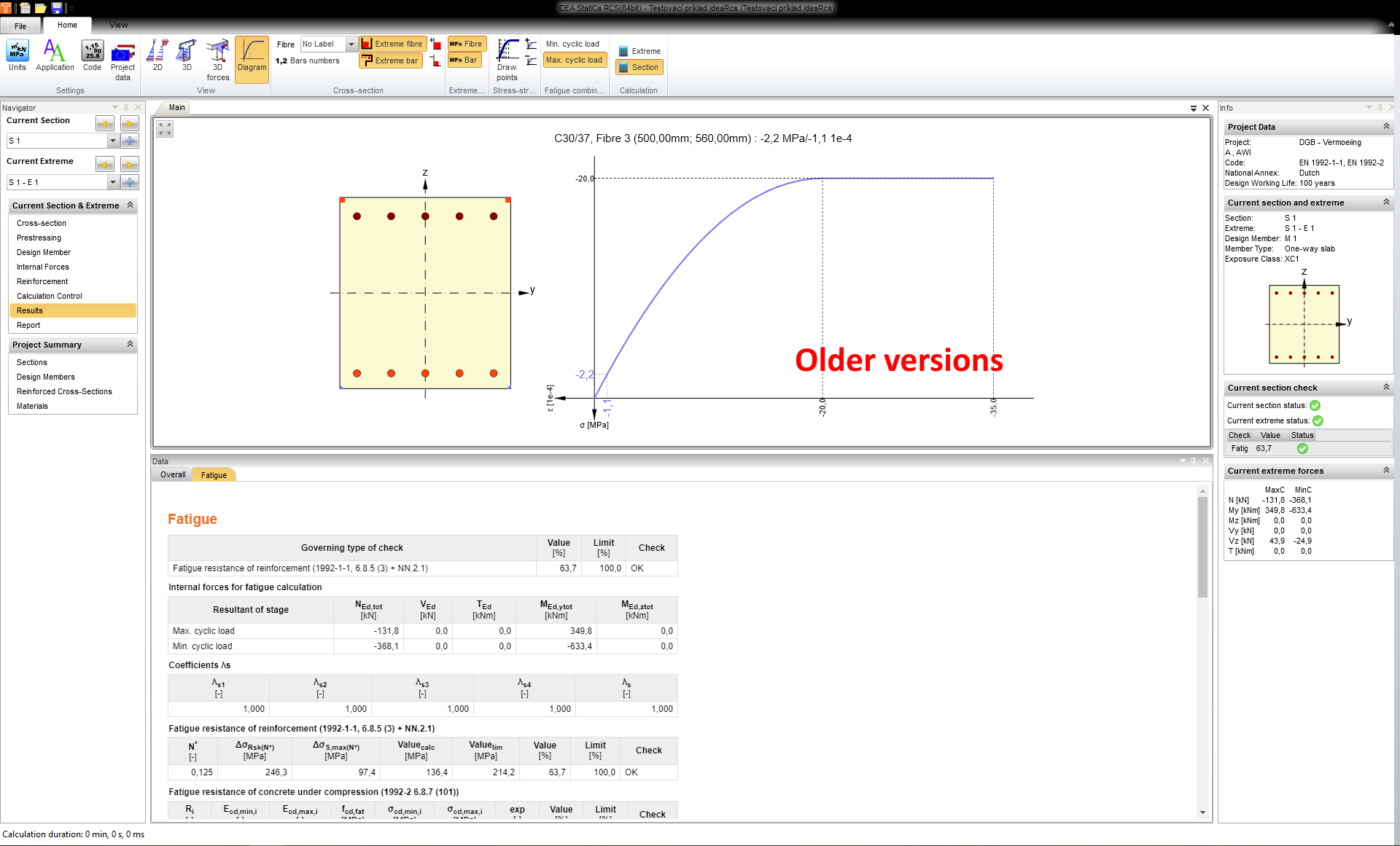
Dans les versions précédentes, lors de l'évaluation du béton à la fatigue, la contrainte dans le béton était calculée sur la base du diagramme contrainte-déformation parabolique-rectangulaire.
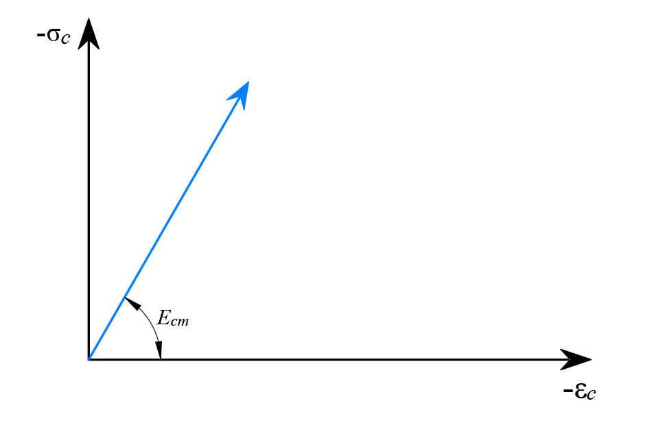
Conformément à l'Eurocode, la résistance à la traction du béton doit être ignorée et une relation contrainte-déformation linéaire pour le béton en compression doit être utilisée. Désormais, pour la vérification à la fatigue, nous utilisons les mêmes diagrammes contrainte-déformation que pour les vérifications à l'ELS, c'est-à-dire un diagramme contrainte-déformation linéaire illimité.
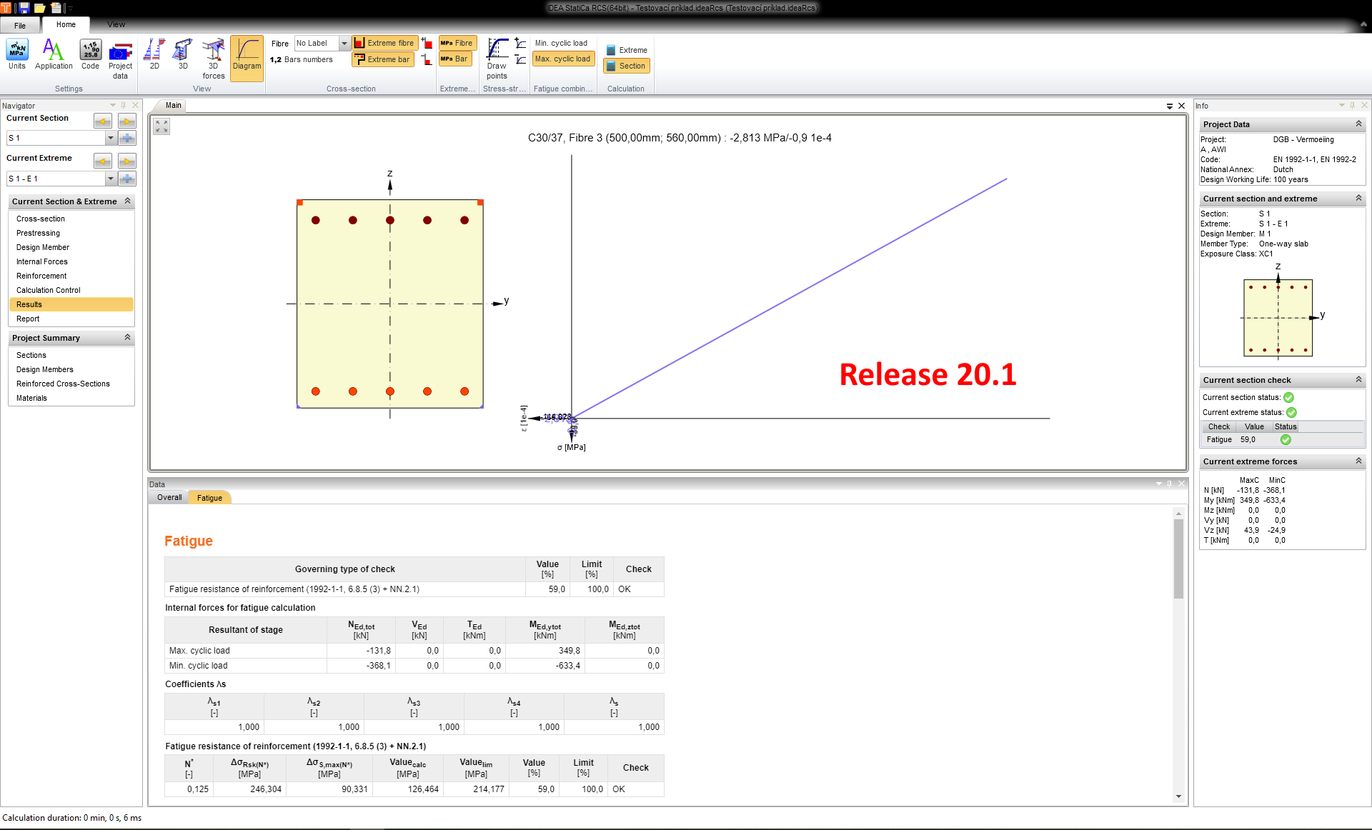
Pour le béton en compression, la valeur moyenne du module d'élasticité de Young Ecm est utilisée.
Liens BIM
Versions des applications prises en charge par IDEA StatiCa 20.1 (Concrete)

Licences
Points forts des améliorations de licences :
- Possibilité de déconnexion automatique après la fermeture d'IDEA StatiCa
- IDEA StatiCa démarre 40 % plus vite
- Messages d'erreur améliorés pour vous informer du problème lié à votre licence
- Nouvelle boîte de dialogue de licence avec le bouton « Mot de passe oublié » à portée de main