Un poteau de section transversale W12\(\times\)79 est ancré dans un bloc de béton (résistance à la compression du béton 4 ksi) par quatre boulons d'ancrage 3/4'' A307 (fy = 50 ksi, fu= 65 ksi). La base du poteau est scellée au coulis. Un contreventement HSS 3.5\(\times\)0.203 est raccordé par un gousset et 2 boulons à glissement contrôlé 3/4'' A490 (fy = 130 ksi, fu = 150 ksi). Tout l'acier est de nuance A36 (fy = 36 ksi, fu = 58 ksi). Le cisaillement est repris par une bêche de section transversale W6\(\times\)25. Les électrodes de soudage E70XX sont sélectionnées. Le poteau est chargé par un effort de compression de –160 kip, un moment fléchissant de 1000 kip-in et un effort tranchant de 20 kip. Le contreventement est chargé par un effort de traction de 30 kip.
Géométrie
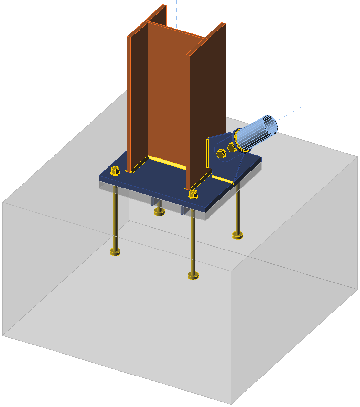
Assemblage étudié
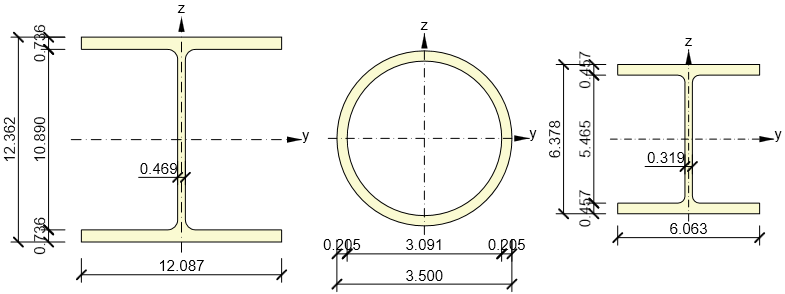
Sections transversales du poteau (gauche), du contreventement (milieu) et de la bêche (droite)
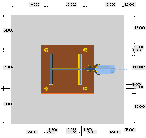
Dimensions du bloc de béton
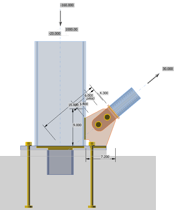
Dimensions du gousset et charges en mode transparent
Vérification manuelle
La vérification manuelle des boulons, des soudures, des plaques et du béton en compression est effectuée conformément à l'AISC 360-16. La capacité de la bêche est déterminée conformément à l'ACI 349-01. Les tiges d'ancrage sont dimensionnées conformément à l'AISC 360-16 – J9 et à l'ACI 318-14 – Chapitre 17.
Les vérifications suivantes sont requises :
- Résistance au glissement des boulons en cisaillement – AISC 360-16 – J3.8
- Résistance à l'arrachement par blocs – AISC 360-16 – J4.3
- Résistance à la traction des éléments assemblés – AISC 360-16 – J4.1
- Résistance des soudures – AISC 360-16 – AISC 360-16 – J2.4
- Résistance au cisaillement de la bêche – AISC 360-16 – G2
- Résistance à la flexion de la bêche – AISC 360-16 – F2.1
- Capacité portante de la bêche sur le béton – ACI 349-01 – B.4.5 et RB11
- Résistance à l'éclatement du béton par la bêche – ACI 349 – B11
- Résistance du béton à la compression par appui – AISC 360-16 – J8
- Résistance de l'acier des ancrages en traction – ACI 318-14 – 17.4.1
- Résistance à l'éclatement du béton – ACI 318-14 – 17.4.2
- Résistance à l'arrachement du béton – ACI 318-14 – 17.4.3
- Résistance à l'éclatement latéral du béton – ACI 318-14 – 17.4.4
Le dimensionnement de la poutre et du poteau est supposé être vérifié par ailleurs.
Distribution des efforts
L'intégralité de l'effort tranchant est supposée être transmise par la bêche au bloc de béton. Le cisaillement est repris uniquement dans le bloc de béton et le coulis est inefficace. L'effort tranchant est la somme de l'effort tranchant dans le poteau et de la composante horizontale de l'effort de traction dans le contreventement, soit \(V=20+30\cdot \cos(40^\circ) = 43\) kip.
L'effort de traction dans le contreventement, 30 kip, doit être transmis par deux boulons précontraints. Les goussets et les soudures doivent être suffisants.
L'effort de compression, 160 kip, est diminué par la composante verticale de l'effort de traction dans le contreventement. La platine de base du poteau doit résister à un effort de compression de \(160-30\cdot \sin(40^\circ) = 141\) kip et à un moment fléchissant de 1000 kip-in.
Vérification de l'assemblage du contreventement
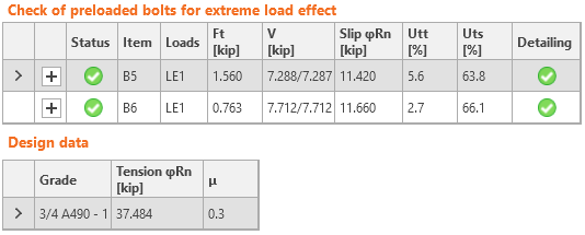
Assemblage à glissement contrôlé
La résistance de l'assemblage à glissement contrôlé est déterminée conformément à l'AISC 360-16 – J3.8. La précontrainte minimale des boulons est tirée du Tableau J3.1 comme \(T_b = 35\) kip. La résistance au glissement d'un boulon est :
\[\phi R_n = \phi \mu D_u h_f T_b n_s = 1 \cdot 0.3 \cdot 1.13 \cdot 1.0 \cdot 35 \cdot 2 = 24 \textrm{kip}\]
La résistance au glissement de 2 boulons, 47 kip, est suffisante pour transmettre l'effort de traction de 30 kip.
Résistance à la traction de la languette
La languette est constituée de deux plaques d'épaisseur 1/4'' afin d'éviter l'excentricité en chargement de compression. Les aires brute et nette en traction sont respectivement \(3.4 \cdot (2\cdot 1/4)=1.7\) in2 et \((3.4-13/16)\cdot (2\cdot 1/4)=1.3\) in2.
\[\phi R_n =\phi F_y A_g = 0.9 \cdot 36 \cdot 1.7 = 55 \textrm{kip} \]
\[\phi R_n =\phi F_u A_n = 0.75 \cdot 58 \cdot 1.3 = 57 \textrm{kip} \]
La résistance de la languette, 55 kip, est suffisante pour transmettre l'effort de traction de 30 kip. Les soudures sont dimensionnées comme des soudures bout à bout à pénétration complète (CJP) et leur résistance doit être équivalente à celle du métal de base.
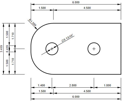
Dimensions de la languette
Résistance à l'arrachement par blocs du gousset
La ligne de plastification attendue sur le gousset pour la rupture par arrachement de blocs est longue de 6,6 in ; la rupture peut se produire sur une ligne plus courte d'un diamètre de trou de boulon, soit 5,8 in. L'épaisseur du gousset est de 3/8''.
\[\phi R_n =\phi F_y A_g = 0.9 \cdot 36 \cdot 2.5 = 80 \textrm{kip} \]
\[\phi R_n =\phi F_u A_n = 0.75 \cdot 58 \cdot 2.2 = 94 \textrm{kip}\]
La résistance du gousset, 80 kip, est suffisante pour transmettre l'effort de traction de 30 kip.
Résistance des soudures du gousset
Les soudures d'angle sont dimensionnées des deux côtés du gousset avec une gorge de 1/4''. Les longueurs des soudures sont de 5,2 in et 4,0 in. Pour éviter le calcul de l'excentricité, on suppose de manière conservative que les deux soudures ont une longueur de 4 in et que chacune reprend la moitié de la charge. La soudure critique est celle chargée à un angle de 40\(^\circ\).
\[F_{nw} = 0.6 F_{EXX} (1+0.5 \sin^{1.5} \theta) = 0.6 \cdot 70 \cdot (1+0.5 \sin^{1.5} 40^\circ) = 53 \textrm{ksi} \]
\[\phi R_n = \phi F_{nw} A_{we} = 0.75 \cdot 53 \cdot 2.83 = 112 \textrm{kip}\]
La résistance des soudures du gousset, 224 kip, est suffisante pour transmettre l'effort de traction de 30 kip.
Vérification de la platine de base du poteau
La platine de base du poteau doit résister à un effort de compression de \(P_u=160-30\cdot \sin(40^\circ) = 141\) kip et à un moment fléchissant de \(M_u=1000\) kip-in. Étant donné que la surface d'appui, A2, est suffisamment grande, la résistance du béton à la compression par appui est :
\[\phi f_{p,(\max)}= \phi 1.7 f'_c = 0.65 \cdot 1.7 \cdot 4 = 4.4 \textrm{ksi} \]
\[\phi q_{\max} = f_{p,(\max)} B = 4.4 \cdot 19 = 83.6 \textrm{kip/in}\]
La platine de base est allongée en raison de l'assemblage du gousset du contreventement. On suppose de manière conservative que l'effort de compression agit au niveau de la semelle du poteau, soit e = 6,18 in depuis le centre de l'assemblage. La distance entre le boulon d'ancrage et le centre de l'assemblage est f = 7,68 in.
\[M_u= eP_r+2fN_{ua} \]
\[N_{ua}=\frac{M_u-eP_r}{2f}=\frac{1000-6.18 \cdot 141}{2\cdot 7.68}=8.4 \textrm{kip} \]
\[Y = \frac{P_r+2N_{ua}}{q_{\max}} = \frac{141+2\cdot 8.4}{83.6} = 1.9 \textrm{in}\]
La résistance portante du béton est suffisante, car la platine de base est assez grande pour accommoder la longueur de la zone d'appui, Y, et l'effort de traction dans l'ancrage est de 8,4 kip. Une vérification plus détaillée de la platine de base incluant la vérification de la plastification de la platine doit être effectuée pour le cas de charge avec l'effort de compression maximal.
Dimensionnement des ancrages
Les ancrages sont de 3/4'', nuance A307, avec une longueur d'encastrement de 12 in dans le bloc de béton, munis de rondelles circulaires de diamètre 1,8 in. Les ancrages sont chargés uniquement en traction car le cisaillement est repris par la bêche. La vérification des ancrages est effectuée conformément à l'ACI 318-14 – Chapitre 17. La résistance de l'acier et la résistance à l'arrachement sont fournies pour les ancrages individuels, et la résistance à l'éclatement du béton et la résistance à l'éclatement latéral du béton sont fournies pour le groupe d'ancrages car \(3h_{ef} \ge s\), où \(h_{ef}\) est la profondeur d'encastrement et s est l'espacement des ancrages.
Résistance de l'acier d'un ancrage en traction – 17.4.1
\[\phi N_{sa}=\phi A_{se,N} f_{uta} \]
\[\phi N_{sa}= 0.7 \cdot 0.334 \cdot 60 = 14 \textrm{kip}\]
Résistance à l'éclatement du béton – 17.4.2
\[h_{ef}=\min \left( \frac{c_{a,\max}}{1.5}, \frac{s}{3} \right ) \le h_{ef} = \max \left(\frac{14}{1.5}, \frac{15.1}{3} \right ) = 9.33 \le 12 \textrm{in} \]
\[A_{Nc} = (14+1.8/2+14) \cdot (14+15.1+14)=1245 \textrm{in}^2 \]
\[A_{Nco} = 9 h_{ef}^2 = 9 \cdot 9.33^2 = 783 \textrm{in}^2 \]
\[N_b = k_c \lambda_a \sqrt{f'_c} h_{ef}^{1.5} = 24 \cdot 1 \cdot \sqrt{4000} \cdot 9.33^{1.5} = 43.3 \textrm{kip} \]
\[\psi_{ec,N} = \frac{1}{1+\frac{2 e'_N}{3 h_{ef}}} = \frac{1}{1+\frac{2 \cdot 0}{3 \cdot 9.33}} = 1 \]
\[\psi_{ed,N} = \min \left ( 0.7 + \frac{0.3 c_{a,min}}{1.5 h_{ef}}, 1 \right ) = \min \left ( 0.7 + \frac{0.3 \cdot 14}{1.5 \cdot 9.33}, 1 \right ) = 1 \]
\[\phi N_{cbg} = \phi \frac{A_{Nc}}{A_{Nco}} \psi_{ec,N} \psi_{ed,N} \psi_{c,N} \psi_{cp,N} N_b \]
\[\phi N_{cbg} = 0.7 \cdot \frac{1245}{783} \cdot 1 \cdot 1 \cdot 1 \cdot 1 \cdot 43.3 = 48 \textrm{kip}\]
Résistance à l'arrachement du béton – 17.4.3
\[A_{brg} = \pi \left ( \frac{d_{wp}^2-d_a^2}{4} \right ) = \pi \left ( \frac{1.8^2-0.75^2}{4} \right ) = 2.1 \textrm{in}^2 \]
\[N_p = 8 A_{brg} f'_c = 8 \cdot 2.1 \cdot 4 = 67 \textrm{kip} \]
\[\phi N_{pn} = \phi \psi_{c,P} N_p = 0.7 \cdot 1 \cdot 67 = 47 \textrm{kip}\]
Résistance à l'éclatement latéral du béton – 17.4.4
\[red = \frac{1+\frac{c_{a2}}{c_{a1}}}{4} = \frac{1+\frac{14}{14}}{4} = 0.5 \]
\[\phi N_{sb} = \phi 160 c_{a1} \sqrt{A_{brg}} \sqrt{f'_c} = 0.7 \cdot 160 \cdot 14 \cdot \sqrt{2.1} \cdot \sqrt{4000}= 144 \textrm{kip} \]
\[\phi N_{sbg} = n \cdot red \cdot \phi N_{sb} = 2 \cdot 0.5 \cdot 144 = 144 \textrm{kip}\]
La résistance la plus faible est celle de l'acier des ancrages, 14 kip. Elle est suffisante pour transmettre la charge de 8,4 kip.
Dimensionnement de la bêche
L'intégralité de l'effort tranchant est supposée être transmise par la bêche au bloc de béton. Le cisaillement est repris uniquement dans le bloc de béton et le coulis est inefficace. L'effort tranchant est la somme de l'effort tranchant dans le poteau et de la composante horizontale de l'effort de traction dans le contreventement, soit \(V=20+30\cdot \cos(40^\circ) = 43\) kip. La section transversale de la bêche est W6x25 et sa longueur est de 6 in. L'épaisseur de la couche de coulis est de 1,5 in, de sorte que la bêche est encastrée de 4,5 in dans le bloc de béton. La pression du béton est supposée uniforme dans le bloc de béton. Le moment fléchissant agissant sur la bêche est égal à l'effort tranchant multiplié par le bras de levier 1,5 + 4,5 / 2 = 3,75 in, soit Mu = 161 kip-in. On suppose que les soudures d'angle sur les semelles et l'âme de la bêche reprennent respectivement le moment fléchissant et l'effort tranchant. Les soudures d'angle sur les semelles doivent transmettre 161 / 5,9 = 27,3 kip.
Capacité portante de la bêche sur le béton – ACI 349-01 – B4.5 et RB11
\[N_y = n A_{se} F_y = 4 \cdot 0.334 \cdot 36 = 48 \textrm{kip} \]
\[\phi P_{br}=\phi 1.3 f'_c A_1 + \phi K_c (N_y - P_a) \]
\[\phi P_{br}=0.7 \cdot 1.3 \cdot 4 \cdot 27.3 + 0.7 \cdot 1.6 \cdot (48 + 141) = 311 \textrm{kip} \ge 43 \textrm{kip}\]
Résistance à l'éclatement du béton par la bêche – ACI 349-01 – B11
\[A_{Vc} = (18.5+6.1+18.5) \cdot (4.5+20) - 6.1 \cdot 4.5 = 1028 \textrm{in}^2 \]
\[\phi V_{cb} = A_{Vc} 4 \phi \sqrt{f'_c} = 1028 \cdot 4 \cdot 0.85 \cdot \sqrt{4000} = 221 \textrm{kip} \ge 43 \textrm{kip}\]
Résistance au cisaillement de la bêche – AISC 360-16 – G2
\[\phi V_n = 0.6 F_y A_w C_{v1}= 1 \cdot 0.6 \cdot 36 \cdot 2 \cdot 1 = 44 \textrm{kip} \ge 43 \textrm{kip}\]
Soudures d'angle de l'âme de la bêche – AISC 360-16 – J2.4
\[F_{nw} = 0.6 F_{EXX} (1+0.5 \sin^{1.5} \theta) = 0.6 \cdot 70 \cdot (1+0.5 \sin^{1.5} 0^\circ) = 42 \textrm{ksi} \]
\[\phi R_n = \phi F_{nw} A_{we} = 0.75 \cdot 42 \cdot 1.93 = 61 \textrm{kip} \ge 43 \textrm{kip}\]
Résistance à la flexion de la bêche – AISC 360-16 – F2.1
\[\phi M_n = \phi M_p = F_y Z_x = 0.9 \cdot 36 \cdot 18.9 = 680.4 \textrm{kip-in} \ge 161 \textrm{kip-in}\]
Soudures d'angle de la semelle de la bêche – AISC 360-16 – J2.4
\[F_{nw} = 0.6 F_{EXX} (1+0.5 \sin^{1.5} \theta) = 0.6 \cdot 70 \cdot (1+0.5 \sin^{1.5} 90^\circ) = 63 \textrm{ksi} \]
\[\phi R_n = \phi F_{nw} A_{we} = 0.75 \cdot 63 \cdot 2.1 = 100 \textrm{kip} \ge 27.3 \textrm{kip}\]
La résistance au cisaillement et à la flexion de la bêche, la résistance des soudures, la capacité portante du béton et la résistance à l'éclatement du béton sont suffisantes pour transmettre l'effort tranchant de 43 kip.
Vérification dans IDEA StatiCa
Les plaques sont vérifiées par analyse par éléments finis. Le modèle de matériau bilinéaire est utilisé avec la limite d'élasticité multipliée par le facteur de résistance de l'acier \(\phi = 0.9\). Les efforts agissant sur les autres composants de l'assemblage, c'est-à-dire les boulons et les soudures, sont également déterminés par analyse par éléments finis, mais leur résistance est vérifiée à l'aide des formules normatives de l'AISC 360-16, de l'ACI 318-14 et de l'ACI 349-01. L'élément de soudure le plus sollicité est vérifié et, avec un chargement supplémentaire, la contrainte dans la soudure se propage vers d'autres éléments de soudure. Par conséquent, la résistance ultime de la soudure est supérieure à celle obtenue en divisant simplement l'effort par le taux de travail de la soudure.
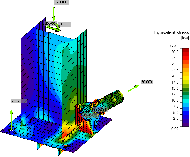
Contrainte de Von Mises
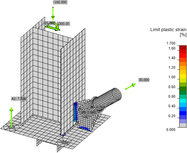
Déformation plastique incluant les efforts de traction dans les ancrages
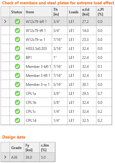
Vérification des contraintes et déformations des plaques
Vérification de l'assemblage à glissement contrôlé
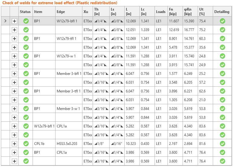
Vérification des soudures
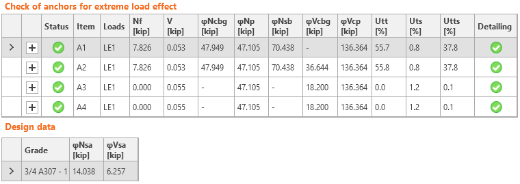
Vérification des ancrages
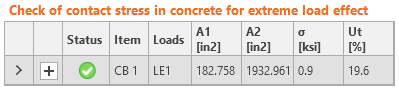
Vérification du béton à la compression par appui
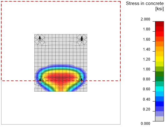
Contrainte dans le béton sous la platine de base et zone de cône d'éclatement du béton
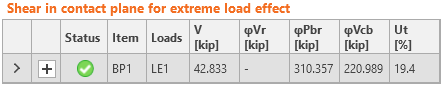
Vérification de la bêche – capacité portante et résistance à l'éclatement du béton
Comparaison
Il est clair que l'analyse par éléments finis montre une distribution des efforts intérieurs différente de celle des hypothèses simplifiées. Le gousset contribue également à la reprise du moment fléchissant, de sorte que le gousset et ses soudures sont bien plus sollicités que dans les hypothèses de calcul standard. Les efforts dans les ancrages sont légèrement inférieurs dans IDEA car la contrainte sous la platine de base n'est pas exactement localisée sous la semelle du poteau. L'élément le plus fortement sollicité dans la vérification manuelle est l'âme de la bêche. Dans IDEA StatiCa, la contrainte équivalente sur l'âme de la bêche est de 30,1 kip, ce qui est proche de la limite d'élasticité.
La vérification normative dans le logiciel de calcul IDEA StatiCa Connection est en accord avec la vérification manuelle conformément à l'AISC 360, l'ACI 318 et l'ACI 341. Les légères différences sont principalement dues aux simplifications des calculs manuels.
Téléchargements joints
- AISC.pdf (PDF, 1,2 MB)