Conception d'un assemblage boulonné platine sur platine (AISC)
1 Nouveau projet
Commencez par lancer IDEA StatiCa Connection. Créez un nouveau projet en sélectionnant le modèle le plus proche de la conception requise, renseignez le nom et la description du projet. Après avoir choisi les propriétés requises, confirmez en cliquant sur Create project.
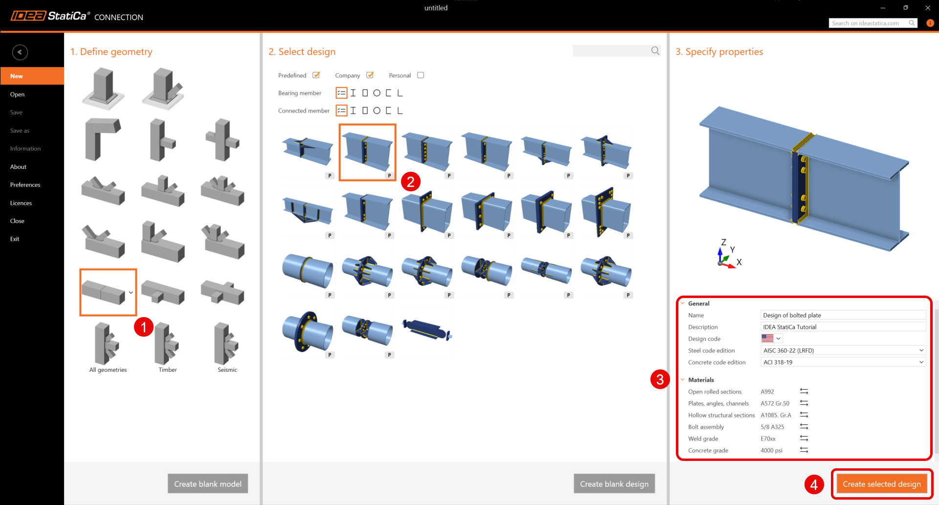
Comme vous travaillez sous le code AISC, définissez les unités impériales (voir Comment changer le système d'unités).
2 Géométrie
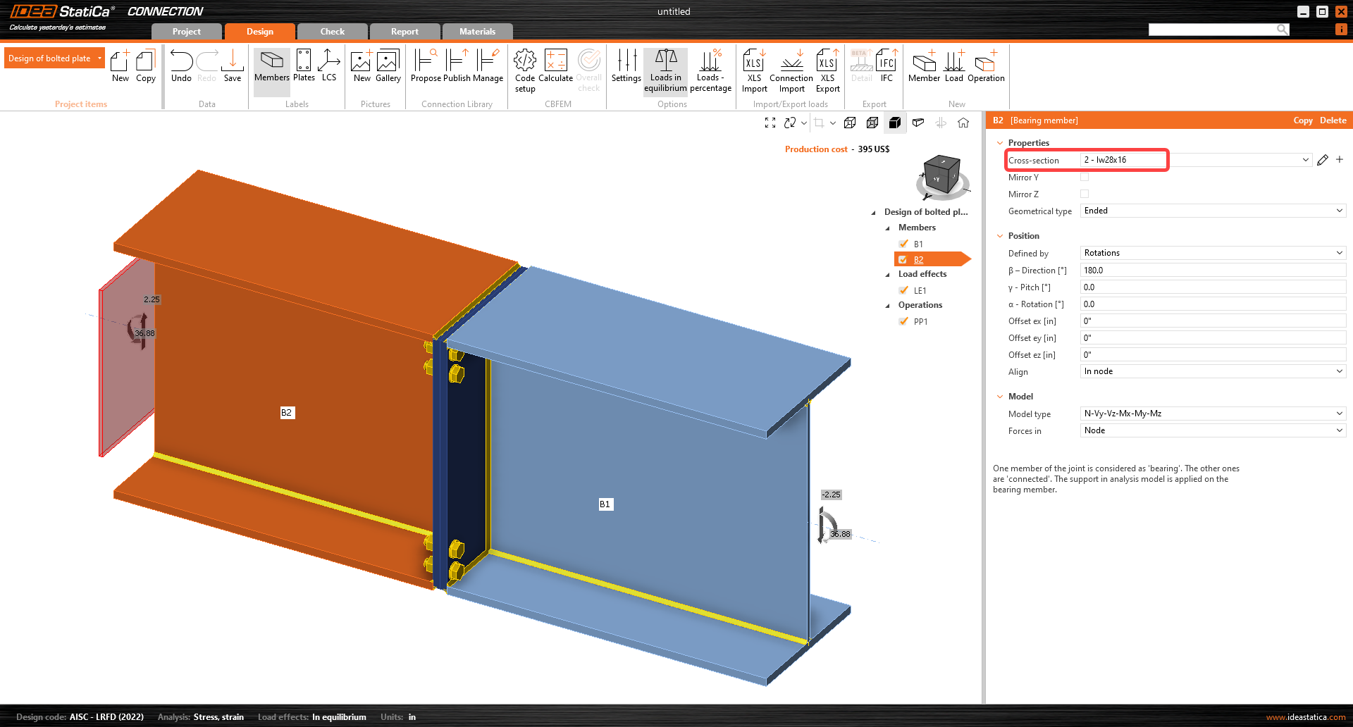
Deux poutres ont été ajoutées automatiquement. Modifiez la section transversale de l'élément B1 en une « section en I soudée » et définissez les dimensions de la section transversale (hauteur, épaisseur et largeur des semelles, épaisseur de l'âme, soudures d'angle entre les plaques).
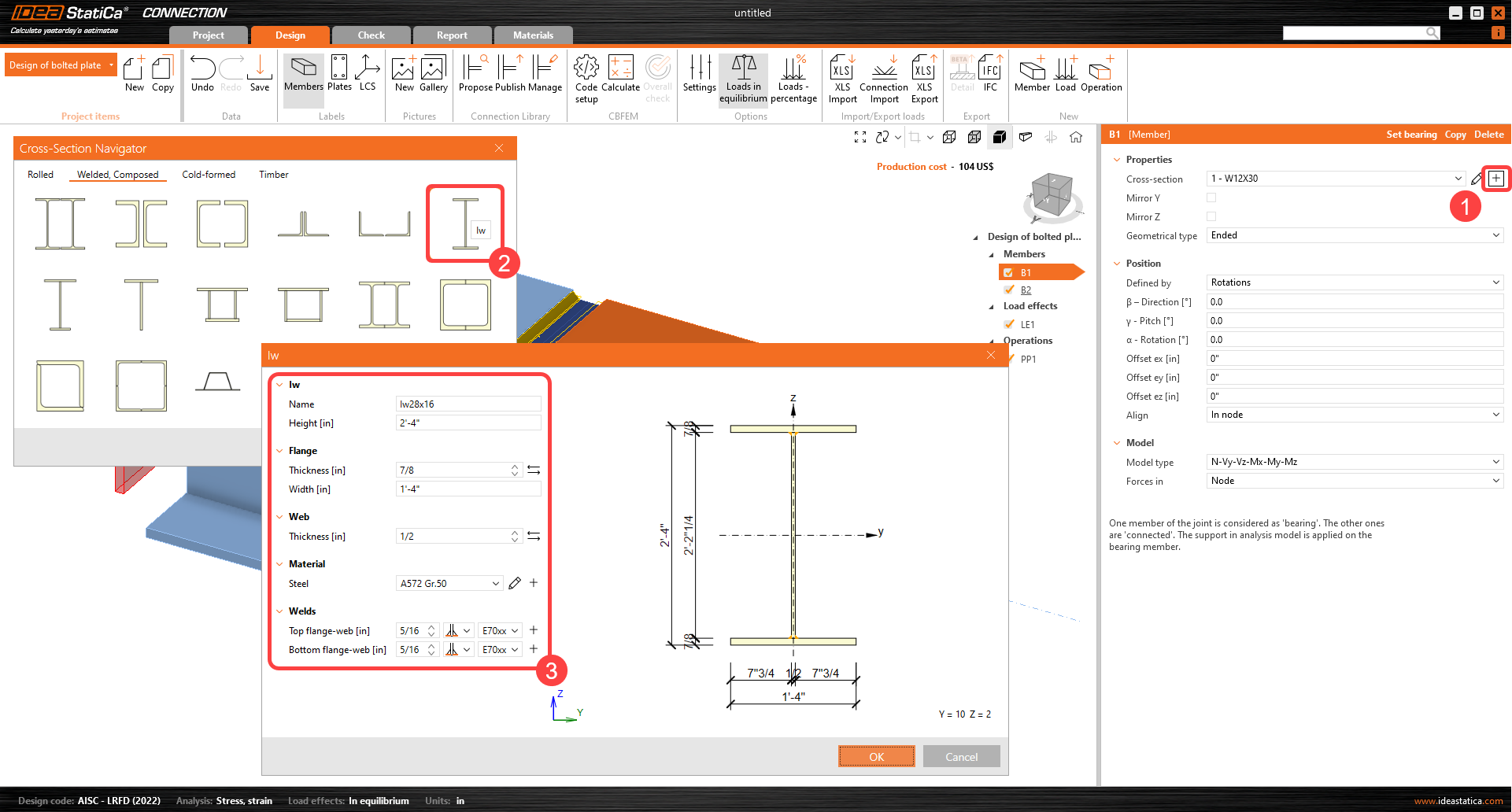
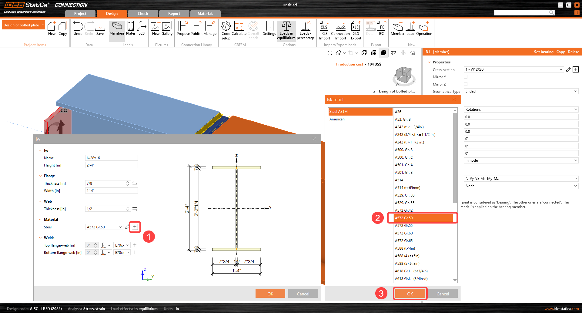
Matériau acier pour la nouvelle section transversale :
Ensuite, pour l'élément B2, sélectionnez la même section transversale dans le menu déroulant.
3 Effets de charge
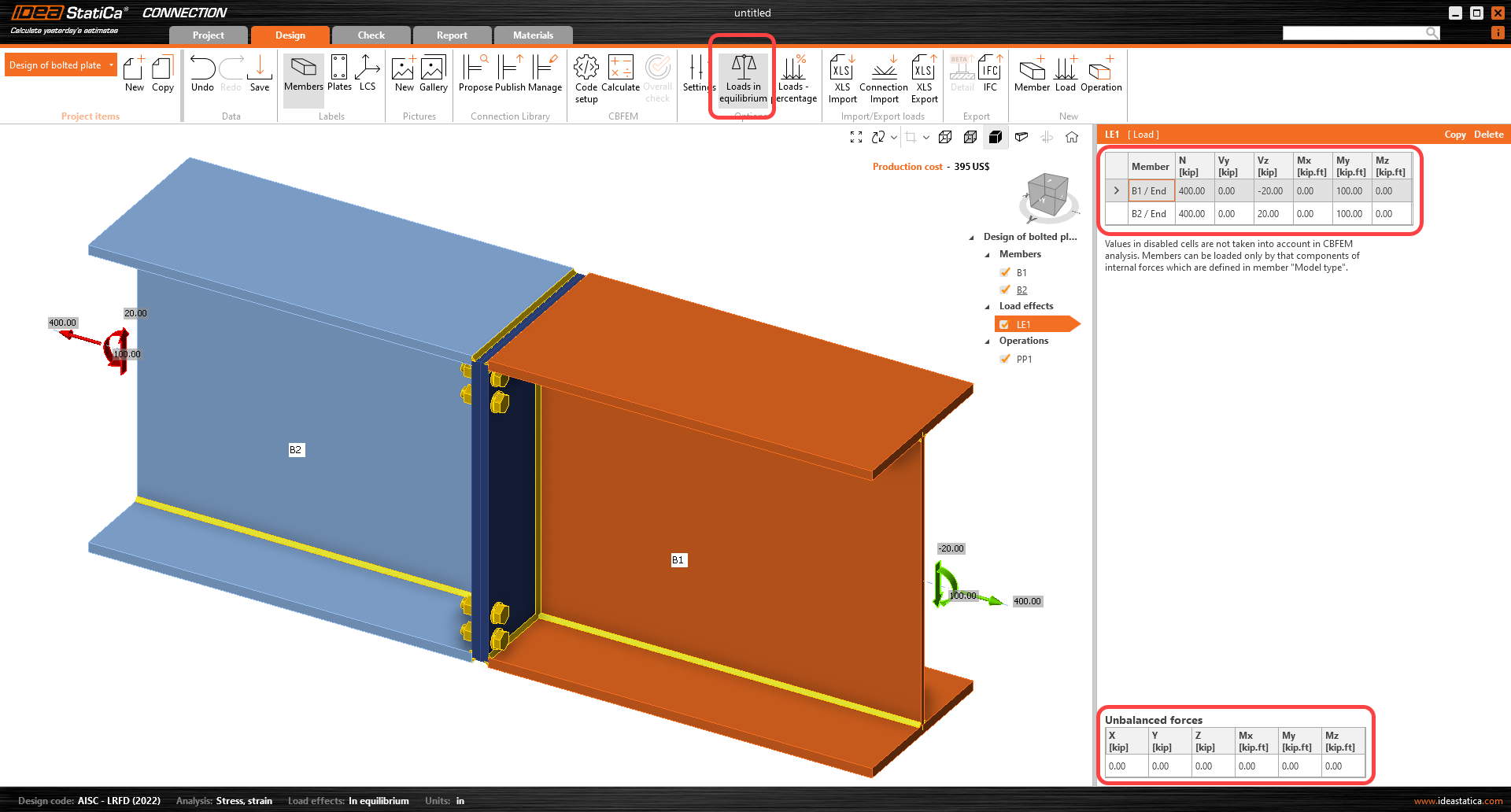
Continuez avec les effets de charge. Un effet de charge a été ajouté automatiquement. L'option Charges en équilibre est active. Saisissez les valeurs des efforts intérieurs dans le tableau. Des cas de charge supplémentaires peuvent être ajoutés.
4 Conception
Avant de modifier l'assemblage, faites un clic droit sur Operations (P) et sélectionnez « Explode ».

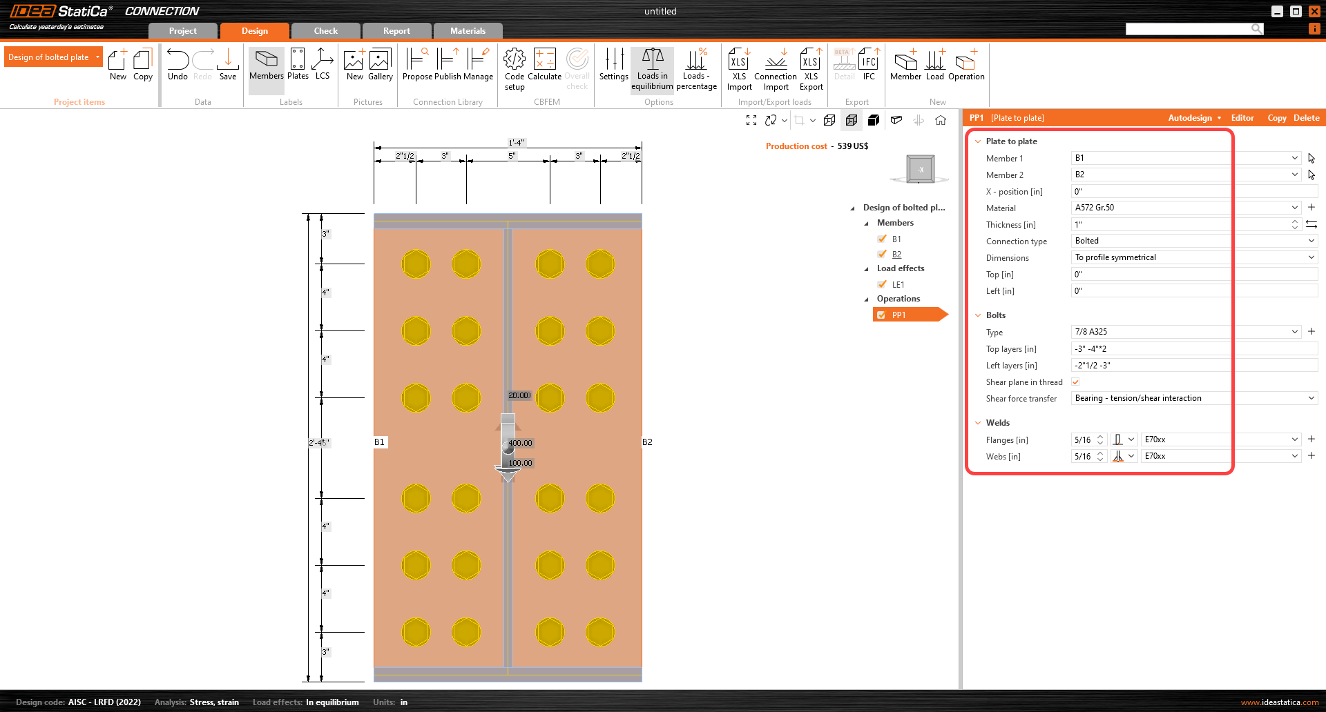
L'opération de fabrication « Plate to plate » a été ajoutée automatiquement. Modifiez ses paramètres géométriques, changez les propriétés des boulons et les propriétés des soudures. Assurez-vous que l'âme comporte une soudure d'angle double face, tandis que les semelles ont des soudures PJP. Des opérations supplémentaires peuvent être ajoutées.
5 Calcul et vérification
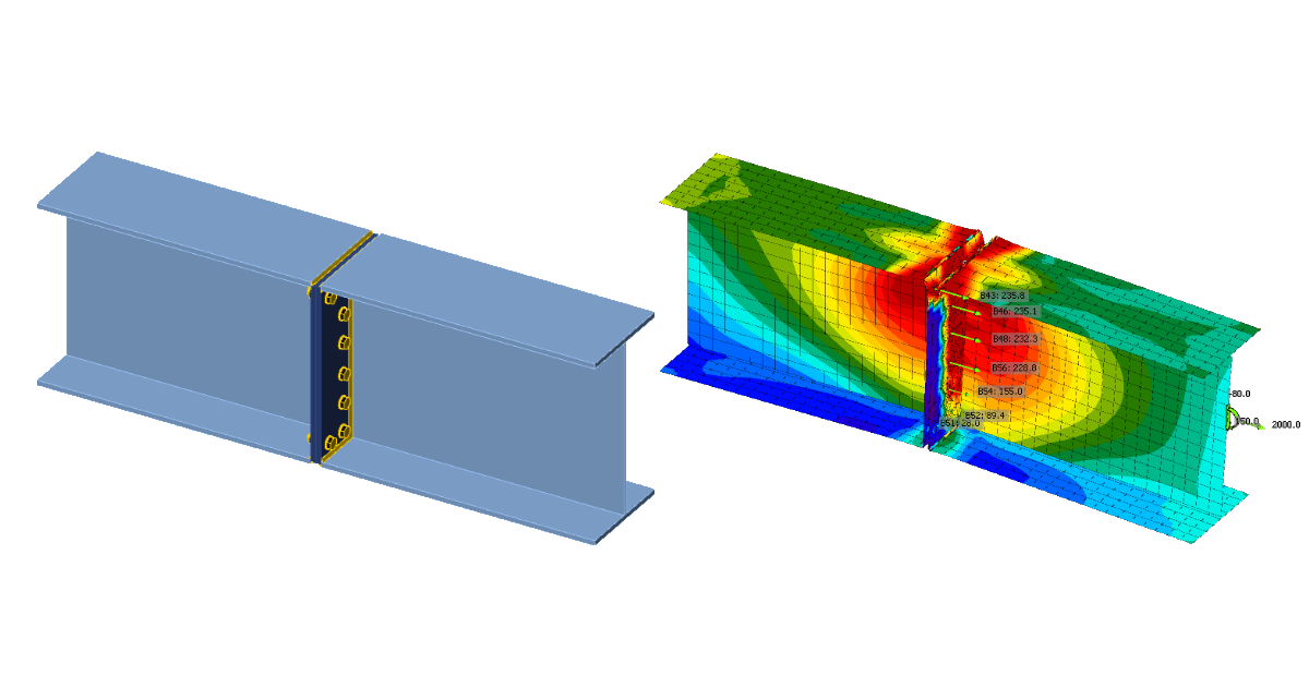
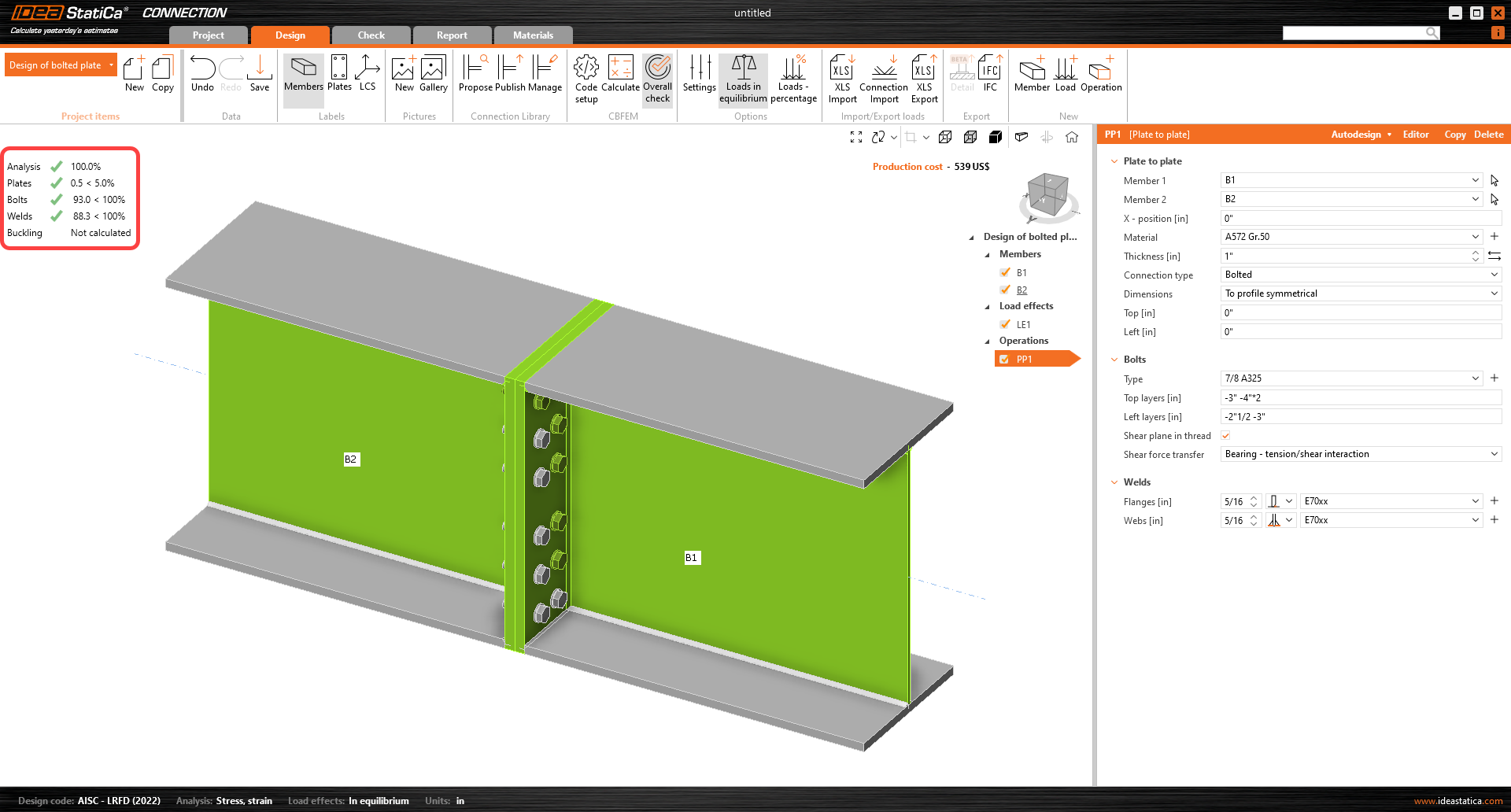
Lancez l'analyse en cliquant sur Calculate dans le ruban. Le modèle d'analyse est généré automatiquement, le calcul basé sur le CBFEM est effectué, et nous pouvons voir la vérification globale affichée avec les valeurs de base des résultats de vérification.
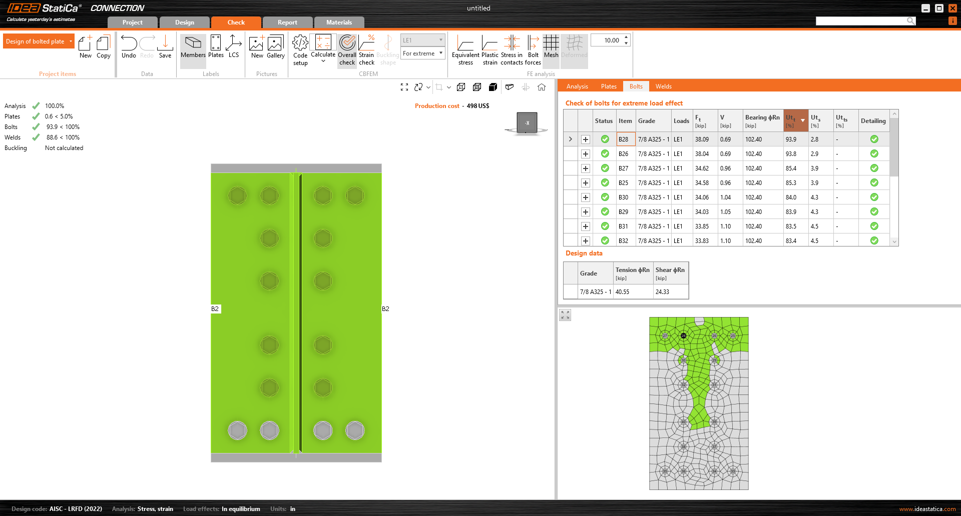
Accédez à l'onglet d'affichage Check, et activez Strain check, Bolt forces, Mesh et Deformed depuis le ruban pour obtenir une vue d'ensemble de ce qui se passe dans l'assemblage. Ouvrez l'onglet Bolts pour constater que certains boulons présentent un taux de travail très faible.
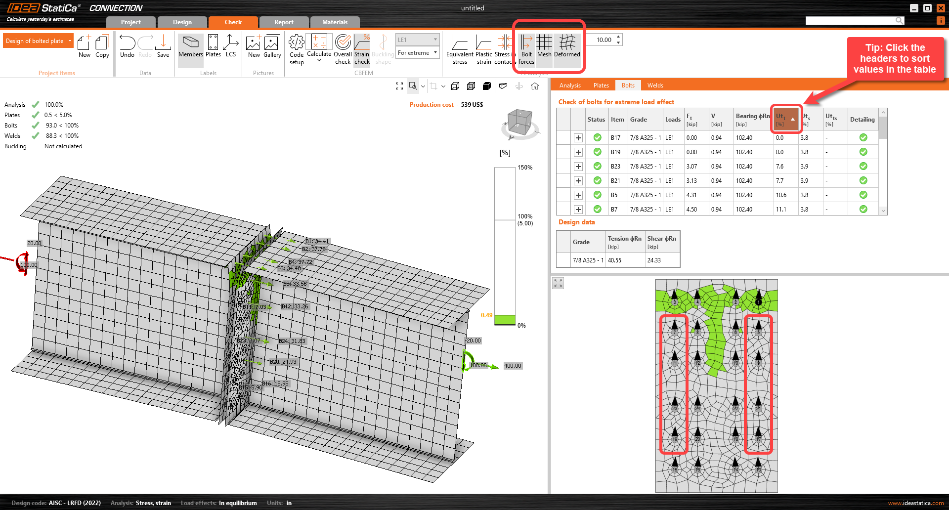
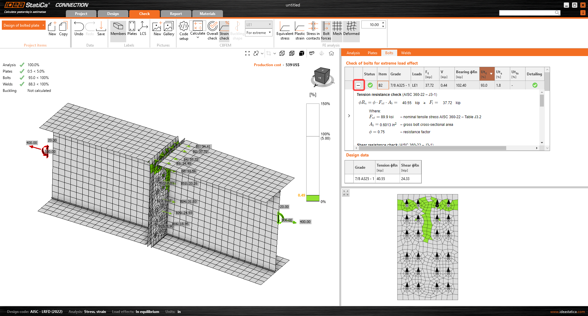
Vous pouvez consulter les équations de vérification normative des boulons dans le menu développé.
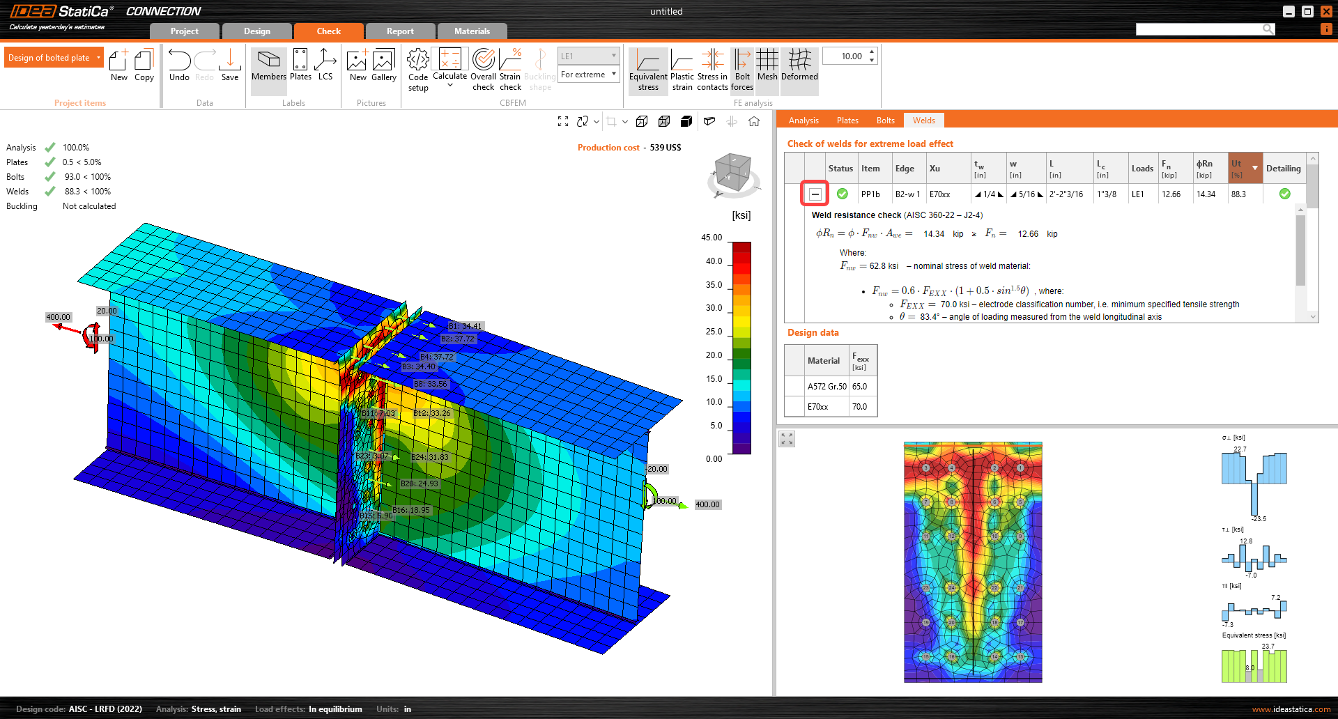
Consultez l'onglet des soudures et examinez les calculs normatifs des soudures :
6 Optimisation
IDEA StatiCa Connection offre un moyen simple d'optimiser la conception des assemblages. Il a été constaté que le taux de travail de certains boulons est quasi nul. Vous pouvez les supprimer et rendre la conception plus économique.
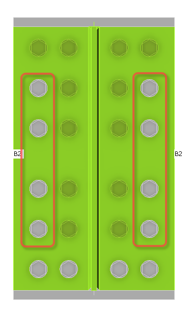
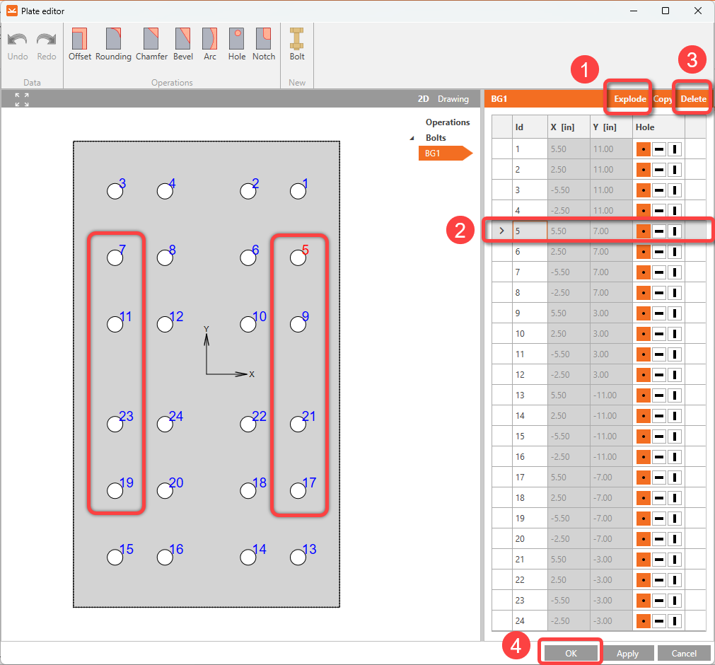
Faites un clic droit sur la platine de liaison et sélectionnez Editor. Cliquez sur Explode. Sélectionnez et supprimez les boulons 5, 7, 9, 11, 17, 19, 21 et 23 en cliquant sur Delete. Répétez l'opération jusqu'à avoir supprimé les boulons mentionnés, puis cliquez sur Apply et OK.
Ensuite, relancez le Calcul et vérifiez les résultats mis à jour. La nouvelle conception satisfait toutes les vérifications, et nous avons économisé 1/3 des boulons initialement prévus.
7 Rapport
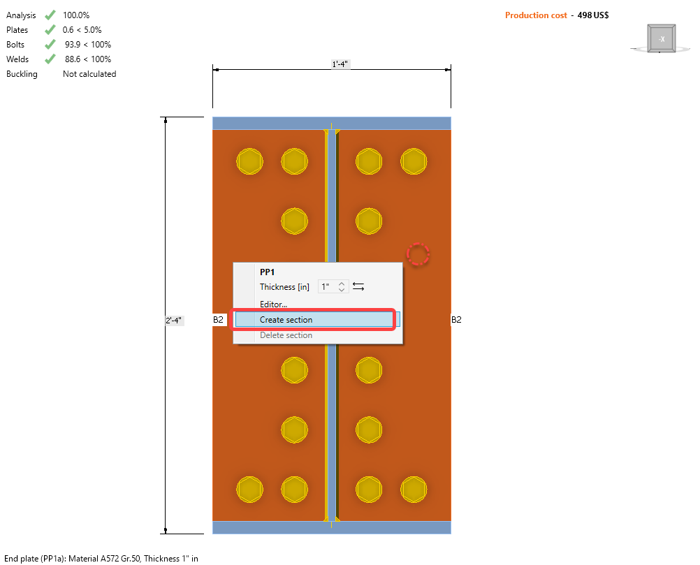
Pour inclure une vue en coupe avec les détails de l'assemblage, faites un clic droit sur la platine et sélectionnez Create section :
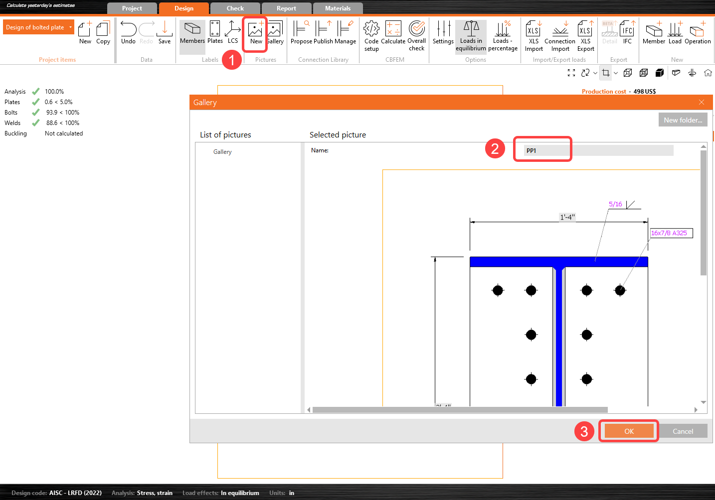
Cliquez ensuite sur New Picture, modifiez le nom, puis cliquez sur OK.
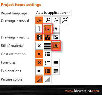
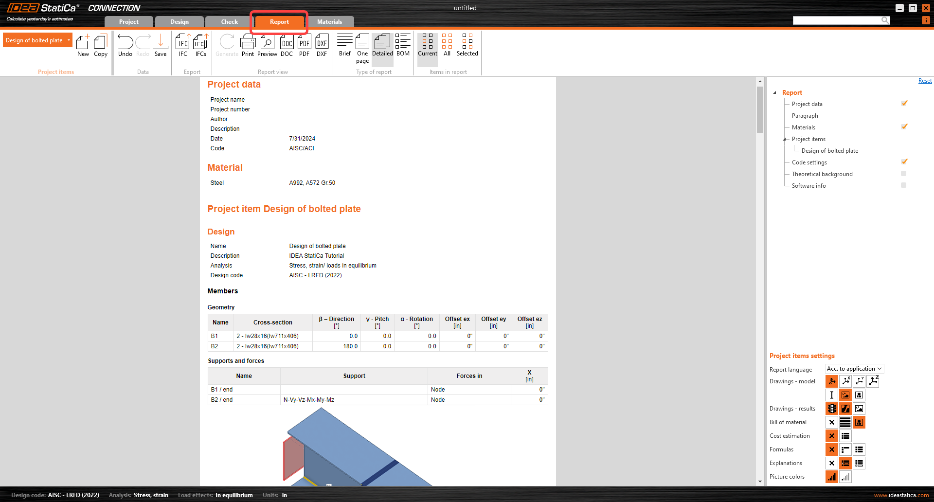
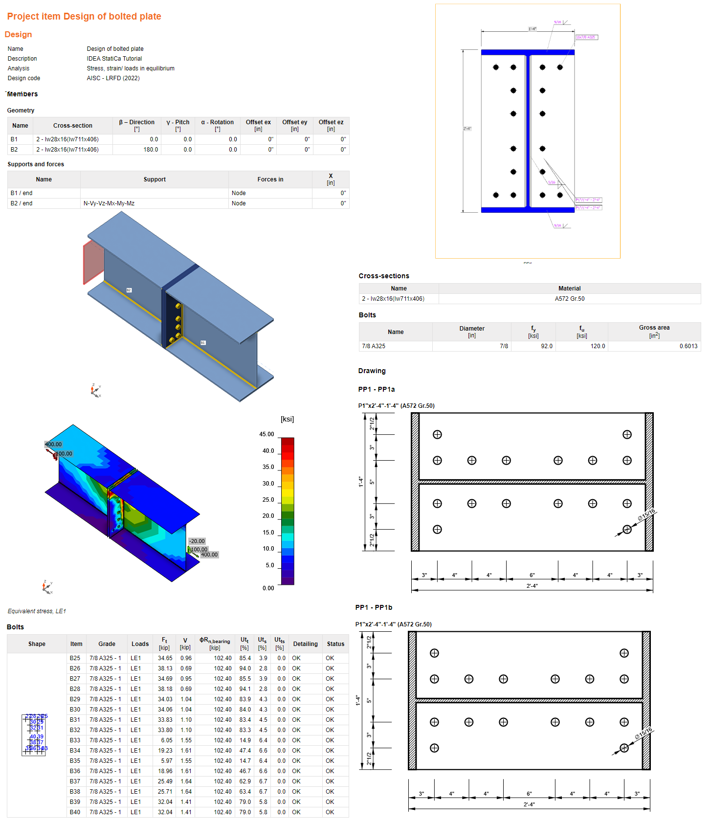
Enfin, accédez à l'onglet Report. IDEA StatiCa propose un rapport entièrement personnalisable à imprimer ou à enregistrer dans un format modifiable. Pour inclure la vue en coupe, sélectionnez l'icône suivante ainsi que la nomenclature pour générer un dessin du détail platine sur platine :
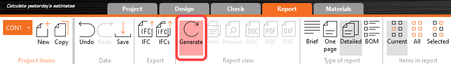
Cliquez sur Generate pour créer le rapport détaillé :
Vous avez conçu, optimisé et effectué la vérification normative d'un assemblage acier structurel selon l'AISC.