1. El objetivo
El objetivo de este artículo es la verificación del módulo LBA (análisis de bifurcación lineal) de la aplicación IDEA StatiCa Member. Se analizan vigas en flexión y se investiga la influencia de diferentes condiciones de contorno y posiciones de carga. Los momentos críticos elásticos resultantes de IDEA StatiCa Member se comparan con los momentos críticos elásticos basados en el Anejo I de EN 1999-1-1 [1]. También se presenta la solución numérica del software LTBeam [2].
2. Descripción del modelo
Se analizaron un total de 18 casos individuales para verificar el módulo LBA. Todos comparten la misma sección transversal IPE 300 y el mismo grado de acero S 355. Se investigaron tres condiciones de contorno diferentes (S – simple, F – empotrado, C – ménsula), cada una con dos casos de carga (F – fuerza; C – continua). Se verifican tres posiciones de carga en relación con el centro de cortante (T – superior, N – neutro, B – inferior).
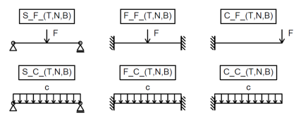
Fig. 1: Diversas condiciones de contorno y casos de carga utilizados para la verificación
Todos los casos se designan de la siguiente manera: "C_F_T", donde "C" indica las condiciones de contorno, "F" el caso de carga y "T" la posición de la carga relativa al centro de cortante.
3. Solución analítica
La fórmula de tres factores del Anejo I de EN 1999-1-1 [1] se utiliza para calcular el momento crítico elástico para el pandeo lateral torsional de las vigas:
\[ M_{cr} = \mu_{cr} \frac{\pi \sqrt{E I_z G I_t}}{L} \]
\[ \mu_{cr} = \frac{c_1}{k_z} \left [ \sqrt{1+\kappa_{wt}^2 + (C_2 \zeta_g - C_3 \zeta_j)^2} - (C_2 \zeta_g - C_3 \zeta_j) \right ] \]
El Anejo B de ECCS - N° 119 [3] se utiliza para calcular los coeficientes C1 y C2 para la ménsula.

Fig. 2: Modos de pandeo para las tres condiciones de contorno diferentes
4. Resultados
El momento crítico elástico de IDEA StatiCa Member (M) se compara con un valor analítico para una sección transversal laminada (EN) y para su representación sin los radios alma-ala (ENw). Además, los mismos dos conjuntos de valores se presentan como resultado del software LTBeam (L, Lw).
Tab. 1: Momentos críticos elásticos resultantes

Los resultados del LBA son conservadores (10–16 %) para las posiciones de carga en el ala superior. Las demás posiciones de carga son menos conservadoras (< 10 %).

Gráfico 1: Valores del momento crítico elástico
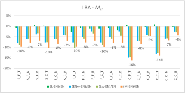
Gráfico 2: Comparación del momento crítico elástico
Los resultados ligeramente conservadores de IDEA StatiCa Member se deben a la ausencia de los radios alma-ala en la representación de lámina de la sección transversal en IDEA StatiCa Member y la consiguiente menor rigidez torsional. Esto se confirma con el software LTBeam (Lw), así como con la solución analítica (ENw).
5. Literatura y referencias
[1] EN 1999-1-1: Eurocódigo 9: Proyecto de estructuras de aluminio - Parte 1-1: Reglas generales estructurales, CEN, 2006.
[2] Software LTBeam v. 1.0.11, CTICM, disponible en https://www.cesdb.com/ltbeam.html
[3] Rules for Member Stability in EN 1993-1-1, Background documentation and design guidelines, ECCS - N° 119, 2006.