Bemessung eines Spannbetonsattelträgers (DIN EN)
1 Neues Projekt
Starten wir IDEA StatiCa und wählen wir die Anwendung Beam.
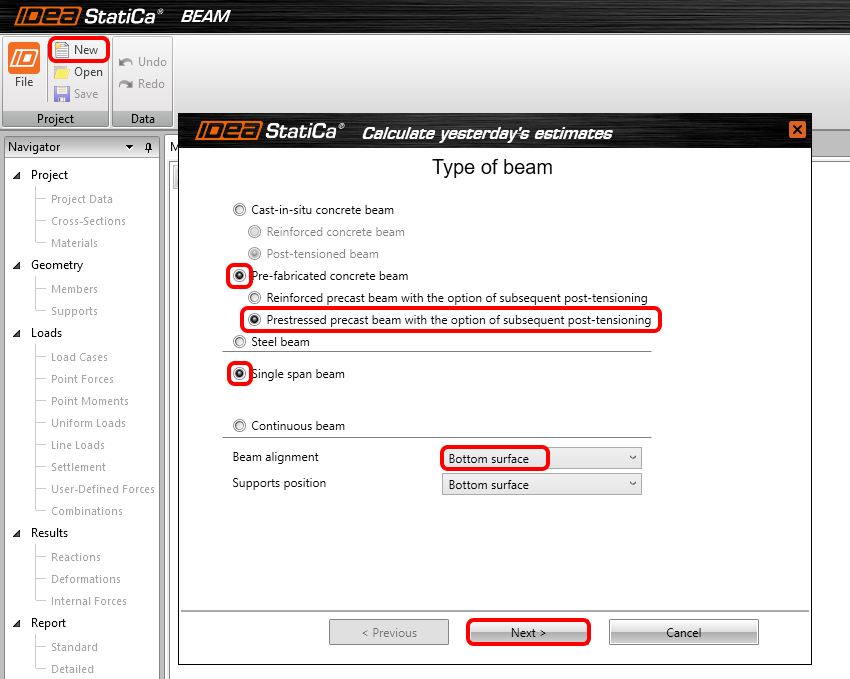
Erstellen Sie ein neues Projekt, indem Sie auf Neu klicken. Das Fenster des Assistenten wird geöffnet, um die Eingabe zu beschleunigen. Beginnen Sie mit der Auswahl von Betonfertigteilträger, vorgespannter Typ und Einfeldträger. Der Sattelträger wird an der Unterseite ausgerichtet, um die richtige Voute zu erzeugen. Fahren Sie mit Weiter fort.
Auf der nächsten Seite stellen Sie die Länge des Trägers auf 16 m ein.

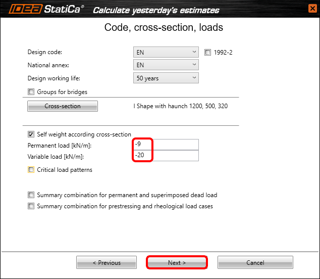
Nun müssen Sie einen Code, den nationalen Anhang, den Querschnitt und die Lasten festlegen. In diesem einfachen Beispiel wählen Sie einen I-Querschnitt mit Vouten aus den erweiterten Querschnitten und ändern die Abmessungen wie folgt.

Nach der Eingabe der variablen Last fahren Sie auf der nächsten Seite fort.
Dort müssen Sie die Belastungsgeschichte definieren. Legen Sie die Daten und Kragarme wie im folgenden Bild dargestellt fest. Bitte beachten Sie, dass sich die Kragarmlänge in den einzelnen Bauabschnitten bis zu den Endlagern ändert. Deaktivieren Sie die Kontrollkästchen in POST, wenn es welche gibt. Nachdem alles eingestellt ist, klicken Sie auf Fertigstellen.

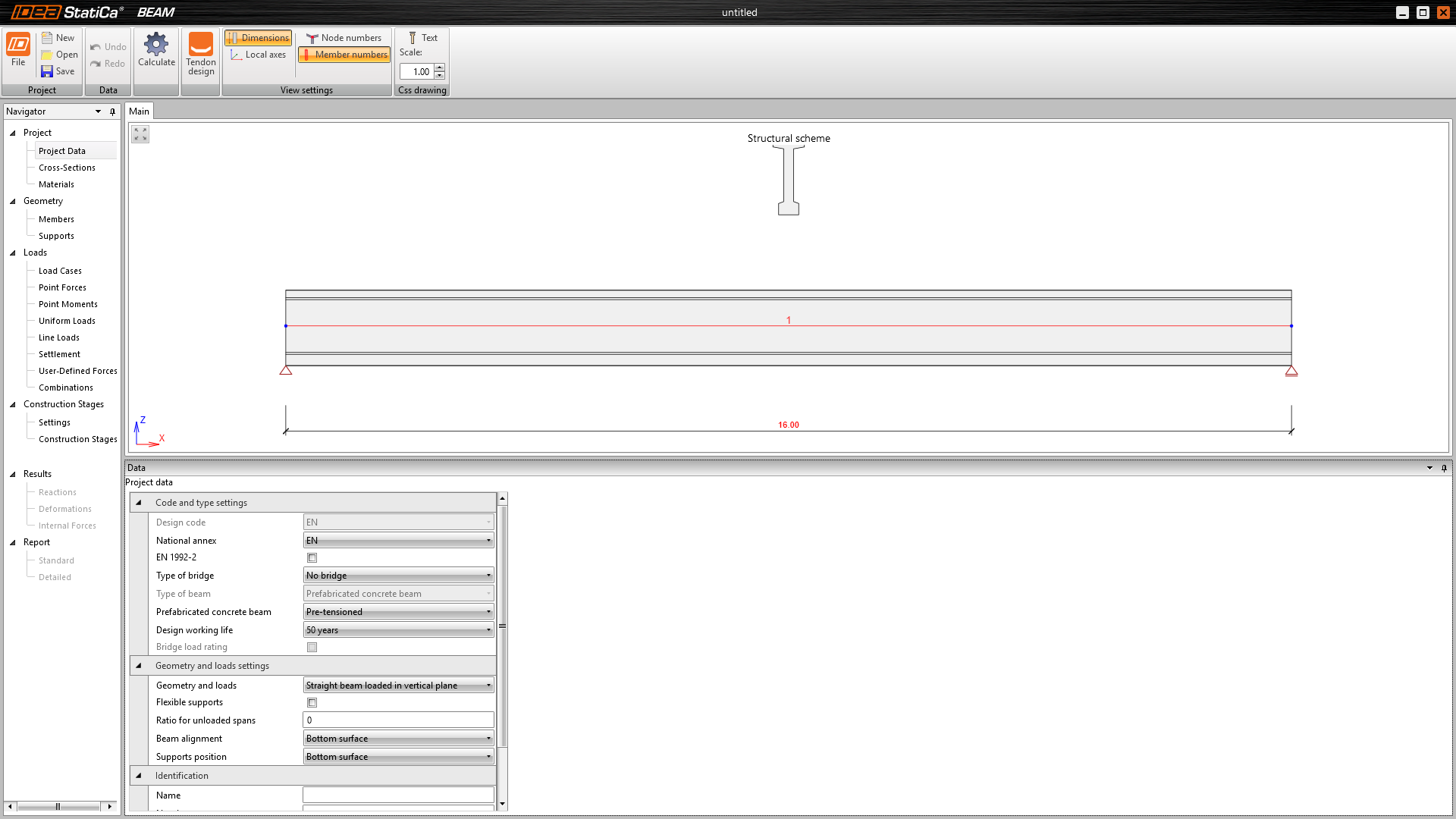
Das folgende Modell wird auf Ihrem Bildschirm angezeigt.
2 Bemessung
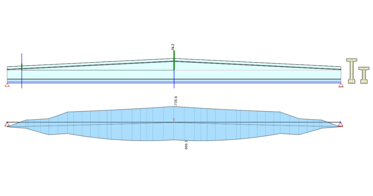
Lassen Sie uns die Geometrie ein wenig ändern, um einen Sattelträger zu erhalten. Gehen Sie auf die Registerkarte Stäbe und ändern Sie den Voutentyp in Symmetrisch und passen Sie seine Länge an. Danach fügen Sie einen neuen Querschnitt hinzu, bei dem Sie lediglich die zuvor definierte Höhe ändern. Nach all diesen Schritten sollten Sie die gleiche Form wie auf dem Bild sehen.

In den nächsten Schritten werden Sie Spannglieder eingeben. Um sie hinzuzufügen, klicken Sie auf den Bemessung Spannglieder in der Multifunktionsleiste.

Es öffnet sich ein neues Fenster und Sie wechseln auf Anordnung der Spannglieder. Sie sehen die X-Y- und X-Z-Ebenen des Trägers, in die Sie die Spanngliedergeometrie eingeben werden. Beginnen wir mit der ersten Reihe von vorgespannten Spanngliedern in Reihe.
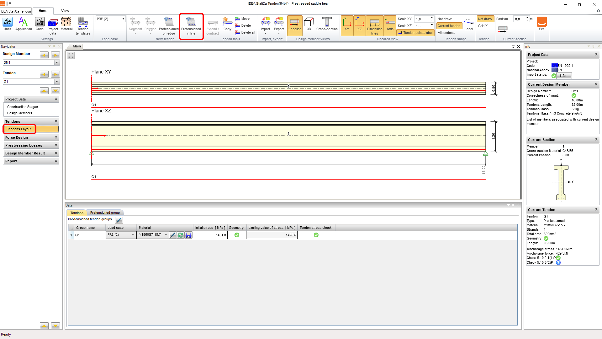
Belassen Sie die Ausgangsspannung auf dem höchstmöglichen Wert, der von der Anwendung empfohlen wird, und beginnen Sie direkt mit der Änderung der Geometrie. Wechseln Sie die Registerkarte zur Gruppe mit Verbund und passen Sie die Eigenschaften wie folgt an:
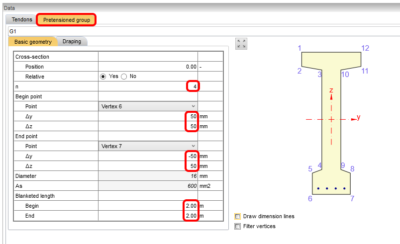
Um die Eingabe der zweiten Reihe zu beschleunigen, verwenden Sie die Kopierfunktion (die nur bei der Definition "in Linie" funktioniert, nicht bei "auf Kante"). Klicken Sie auf die Schaltfläche Kopieren und stellen Sie den Wert Offset Z ein.

Die abgedeckte Länge (Abisolierung) wird nicht mit der Geometrie kopiert, Sie brauchen sie also nicht zu entfernen. Wenn Sie alle Spannglieder im Querschnitt prüfen möchten, können Sie die Ansicht im Menüband umschalten. Wenn Sie mit dem Layout zufrieden sind, können Sie zurück in die Beam-Anwendung wechseln, indem Sie auf die Schaltfläche Beenden klicken.

Der nächste Halt ist bei den Einstellungen der Bauzustände. Normalerweise würde die Lösung mit dem linearen Kriechen ausreichen, aber nicht in diesem Fall. Damit Sie uns vertrauen können, haben wir dieses Beispiel mit einer linearen Kriechlösung vorgerechnet und Sie können sehen, dass bei der Vorspannung der Grenzwert für die quasi-ständige Kombination mit dem angewandten r-sup-Faktor überschritten wird.

Diese Situation kann vermieden werden, wenn Sie die Berechnungen des nichtlinearen Kriechens durchführen, so dass der Grenzwert nur noch für charakteristische Kombinationen gilt. Die Anforderungen hierfür sind in der EC 1992-1-1 Kapitel 3.1.4 Artikel (4) zu finden.

Eine weitere nützliche Funktion für vorgefertigte Balken ist eine benutzerdefinierte Betonfestigkeit im Stadium der Vorspannung. Mit dieser Einstellung können Sie die Analyse für Bauteile durchführen, die jünger als 3 Tage sind, da Sie den Wert anhand von Tests überprüfen. Sie können auch alle zu prüfenden Phasen auswählen.

Sie müssen nun die TDA-Berechnung ausführen, um die Ergebnisse des Modells über die Schaltfläche Berechnen zu erhalten.

Nachdem die Berechnungen durchgeführt wurden, können Sie sich die Ergebnisse der Reaktionen, der linearen Verformungen und der Schnittgrößen ansehen.

Der nächste Teil befasst sich mit der der Überprüfung des Modells. Zunächst müssen Sie alle durchzuführenden Nachweise und die richtigen Einstellungen für die Nachweise wie z. B. die Expositionsklassen festlegen. In diesem Fall deaktivieren Sie das Kontrollkästchen Detaillierung, da es in diesem Beispiel nicht notwendig ist, sie zu überprüfen.

Lassen Sie uns nun mit der Bewehrung des Trägers fortfahren. Es gibt Bewehrungszonen im Träger, die modifiziert werden können (Sie können auch einige Vorlagen dafür verwenden). Sie werden die Bewehrung für die erste Zone A-A eingeben, indem Sie auf das Bild der Form in der Szene klicken.

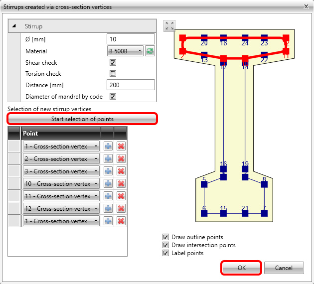
Der Bewehrungseditor öffnet sich und Sie beginnen mit der Definition des Bügels auf dem Steg. Wechseln Sie auf den Reiter Bügel und klicken Sie dann auf Neu aus Punkten.

Es öffnet sich ein Dialog, in dem Sie die Eigenschaften der Bügel ändern und die Punkte auswählen können. Fahren Sie fort, indem Sie auf OK klicken.

Wiederholen Sie die Schritte für den zweiten Bügel zur Verstärkung des unteren Flansches, aber deaktivieren Sie diesmal das Kontrollkästchen für den Torsionsnachweis. Schauen Sie sich bitte die Details oben im FAQ-Bereich an, da dies die richtige Einstellung für die Berücksichtigung eines entsprechenden dünnwandigen Querschnitts ist.

Mit diesen Schritten verstärken Sie zum letzten Mal den oberen Flansch.
Wechseln Sie nun zum Register Längsbewehrung und beginnen Sie mit Neu auf Kante. Um die nächsten Schritte zu sehen, ist es hilfreich, die Anzahl der Kanten einzuschalten. Stellen Sie dann den Durchmesser und die Anzahl der Stäbe wie folgt ein:

Wiederholen wir dies für eine andere Kante.
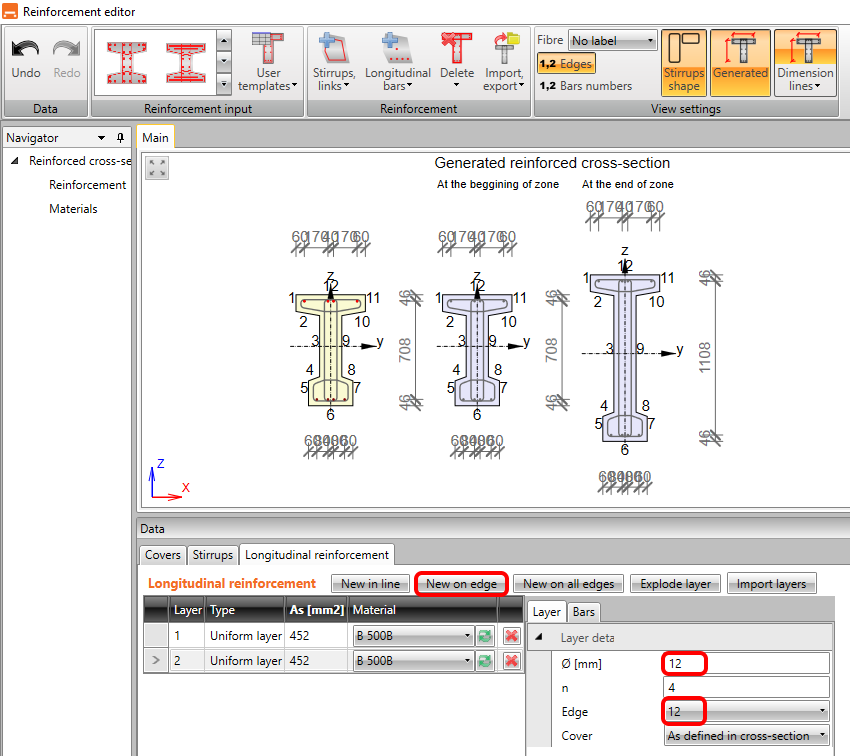
Sie geben die letzte Lage der Längsbewehrung an der Kante Nummer 6 ein, allerdings mit einer größeren Überdeckung. Diese Lage wird Ihnen beim Interaktionsnachweis helfen, da sie die Kräfte mehr auf die Längsbewehrung umverteilt. Sie verstärken nicht den gesamten Abschnitt, um in dieser Übung Zeit zu sparen.

Nachdem Sie auf OK geklickt haben, sollten Sie sehen, dass die Zone A-A an beiden Enden des Trägers bewehrt ist. Sie definieren nun die Querschnitte für einen Nachweis bei 0,8m und 7,2m (Sie können die Schnittgrößen einzeichnen, um zu sehen, dass das maximale Moment etwas links und rechts von der Mitte der Spannweite liegt und der Querschnitt hier kleiner ist).

Wenn die Bewehrung fertig ist, sind als letzte Eingabe die Parameter der Seitenstabilität erforderlich. Geben Sie Folgendes ein: die Breite des Flansches unter Druck, die Höhe in der Mitte der Spannweite, die Knicklänge für Torsion und die Art der Situation. Der Nachweis ist sofort verfügbar.

3 Ergebnisse
Um die Nachweise auszuführen, klicken Sie im Navigator auf Ergebnisse. Das erste, was Sie nach den Berechnungen sehen, ist eine Zusammenfassung aller Nachweise. Der schnellste Weg, um sicherzustellen, dass alles in Ordnung ist, ist ein Blick auf die rechte Seite des Bildschirms.

Das obere Menüband ermöglicht es uns, die Ergebnisse durchzugehen, und Sie können die Auslastung des Modells immer im Bild sehen. Werfen wir einen Blick auf die Auslastung der Spannungsbegrenzungsnachweise für Beton.

Wenn Sie die detaillierten Ergebnisse in einer visualisierten Form sehen möchten, können Sie alle Zonen in das RCS-Modul von Detail exportieren .

Sie landen auf der Registerkarte RCS Section, wo Sie mit der Schaltfläche All Berechnungen durchführen können.
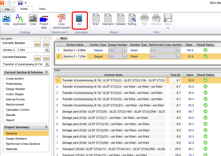
Wenn Sie zu den Ergebnissen gehen und zwischen den Registerkarten wechseln, können Sie alle für den ausgewählten Abschnitt durchgeführten Nachweise durchgehen.

Um zurück zu IDEA StatiCa Beam zu gelangen, schließen Sie einfach das RCS-Fenster.
4 Bericht
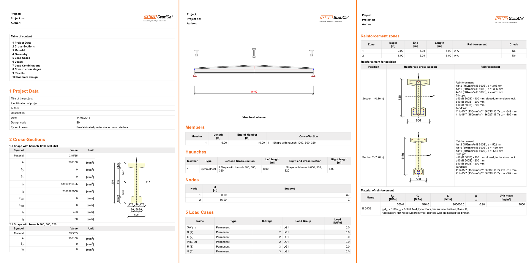
Zuletzt gelangen Sie zur Berichtsvorschau/Drucken. IDEA StatiCa bietet einen vollständig anpassbaren Bericht, den Sie ausdrucken oder in einem editierbaren Format speichern können.

Sie haben einen vorgespannten Doppelstegträger nach Eurocode bemessen, bewehrt und nachgeprüft.