Schlanke Betonstütze (EN)
1 Neues Projekt
Öffnen Sie IDEA StatiCa und wählen Sie die Member -Anwendung.

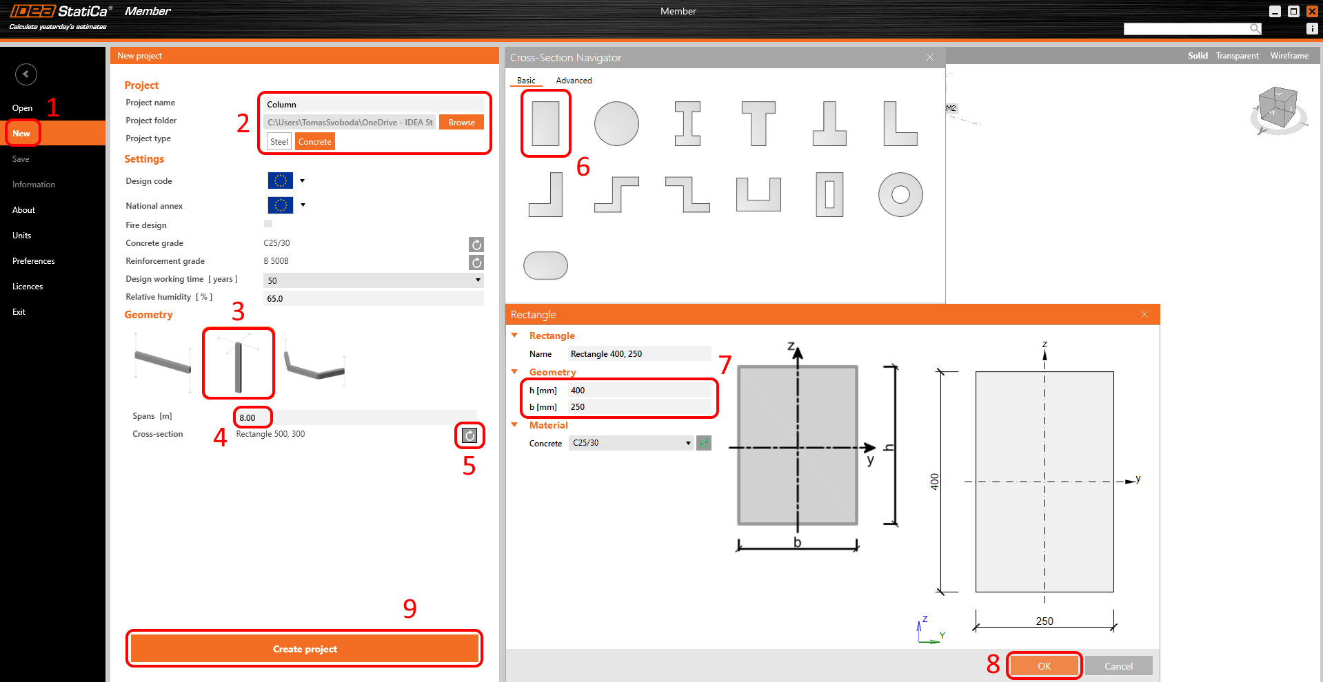
Erstellen Sie ein neues Projekt (1), geben Sie dessen Namen ein und wählen Sie einen Ordner, in dem es gespeichert werden soll. Wählen Sie dann den Projekttyp Beton (2) und den Typ der Topologie (3). Definieren Sie die Höhe der Stütze mit 8 m (4). Klicken Sie auf den Pfeil (5), um den Querschnitt festzulegen. Wählen Sie den rechteckigen Querschnitt (6). Ändern Sie die Abmessungen (7) und klicken Sie auf die Schaltfläche OK (8). Klicken Sie abschließend auf Projekt erstellen (9).
2 Bemessung
Die Stütze wird nun mit den zugehörigen Bauteilen erstellt. Löschen Sie alle zugehörigen Bauteile.

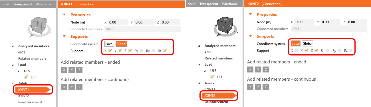
Die Lagerungsbedingungen müssen angepasst werden. Wählen Sie dazu JOINT1 und ändern Sie die Lagerung. Wählen Sie anschließend das zweite JOINT2 und passen Sie auch dort die Lagerung an. Die Freiheitsgrade sind in der nachfolgenden Abbildung definiert.
Im nächsten Schritt wird die Bewehrungsanordnung definiert. Wählen Sie das analysierte Bauteil AM1 (1) und klicken Sie auf die Schaltfläche Bewehrungskorb (2). Geben Sie dann die Bewehrung (3) mithilfe der Vorlage ein. Die Werte sind bereits eingestellt – überprüfen Sie diese (4) und bestätigen Sie (5).

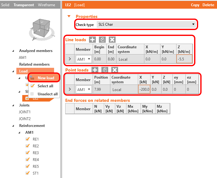
Das letzte zu definierende Element ist die Belastung. Legen Sie drei Lastfälle fest.

Um eine neue Lastkombination hinzuzufügen, können Sie mit der rechten Maustaste auf „Last" klicken und Neue Last auswählen.

Erstellen Sie nun den Hilfslastfall LE4. Dieser Lastfall wird verwendet, um die zusätzliche Exzentrizität zur Berücksichtigung des Kriecheffekts im Modell zu bestimmen. Kopieren Sie den Lastfall LE3 und setzen Sie den neuen auf den Nachweistyp GZT.

3 Nachweis
Das Modell ist fertig. Klicken Sie auf Berechnen, um die Lineare Analyse durchzuführen.

Sobald die lineare Analyse abgeschlossen ist, können Sie auf der linken Seite des Bildschirms eine Zusammenfassung der Ergebnisse einsehen. Sie können Schnittgrößen, Verformungen und Auflagerkräfte mithilfe der 1D-Ergebniswerkzeuge überprüfen oder die Normnachweis-Ergebnisse durchsehen. Für den detaillierten Normnachweis klicken Sie auf die Schaltfläche Detailliert.
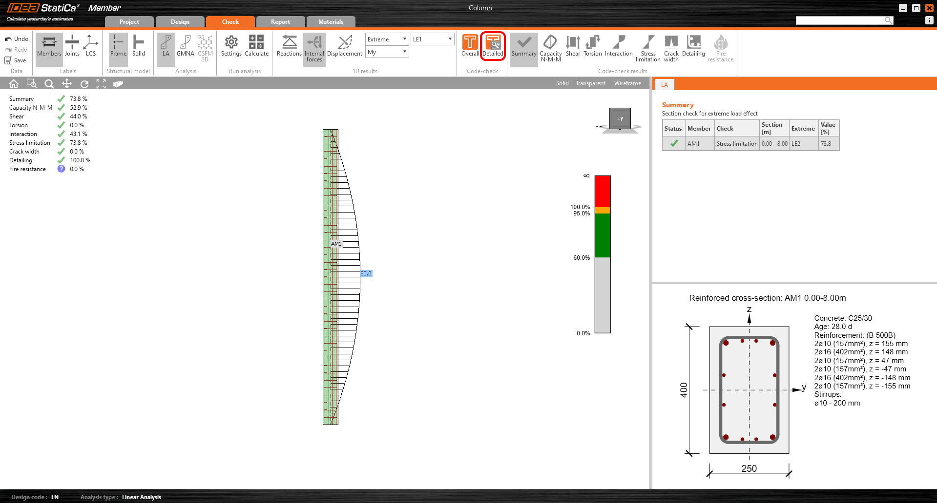
Das RCS-Modul wird geöffnet. Um einen Querkraft-Normnachweis durchzuführen, gehen Sie im Navigator zu Ergebnisse und wählen Sie die Registerkarte Querkraft. Die GMNIA berücksichtigt keine Querkraft und Torsion. Der Querkraftnachweis muss mithilfe der linearen Analyse und des RCS-Moduls durchgeführt werden.

Sie können alle Ergebnisse durchsehen. Gehen Sie beispielsweise zum Nachweis der Spannungsbegrenzung und ändern Sie das aktuelle Extremum.

Sie können diese lineare Spannung nach Abschluss aller nichtlinearen Berechnungen mit den nichtlinearen Ergebnissen vergleichen.
Schließen Sie das RCS-Modul und fahren Sie mit der MNA – Materiell nichtlinearen Analyse – fort.

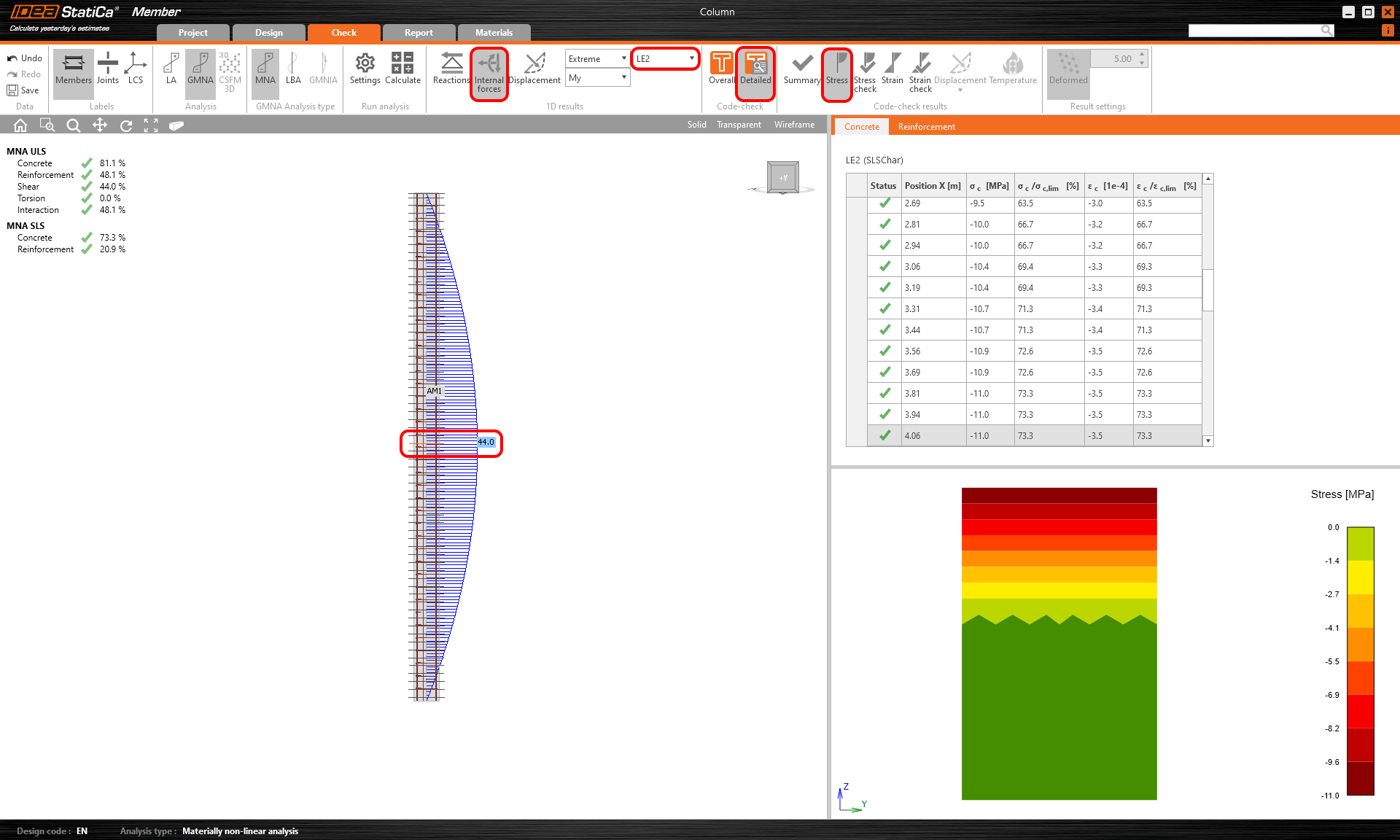
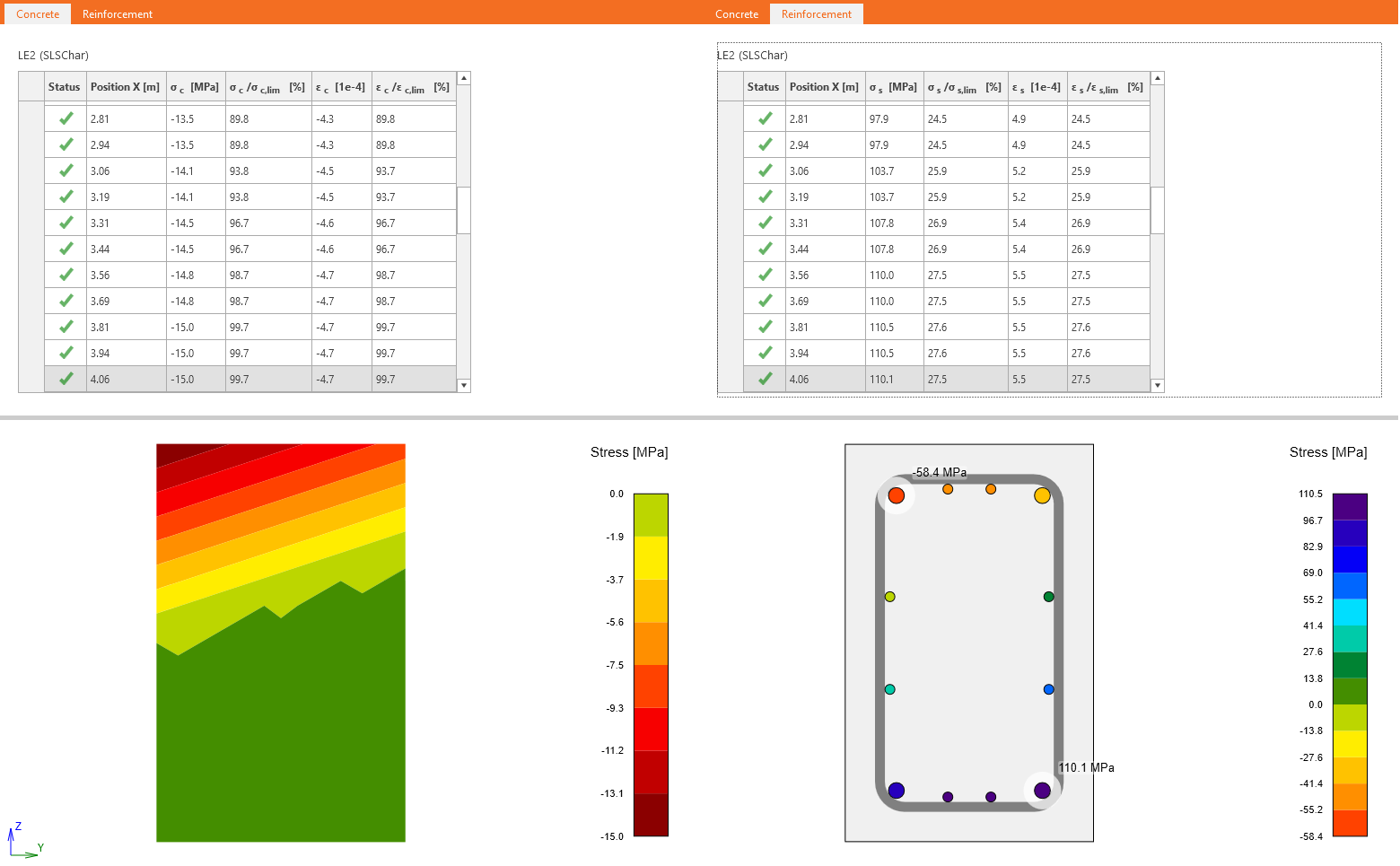
Sobald die Berechnung abgeschlossen ist, können Sie die Ergebnisse überprüfen und mit den Ergebnissen aus dem RCS-Modul vergleichen. Wählen Sie dazu die GZG-Lastkombination LE2, klicken Sie auf Detailliert und dann auf Spannung. Anschließend müssen Sie den maßgebenden Querschnitt auswählen. Danach können Sie feststellen, dass eine gute Übereinstimmung zwischen den Spannungen aus dem RCS-Modul und der MNA-Analyse besteht.
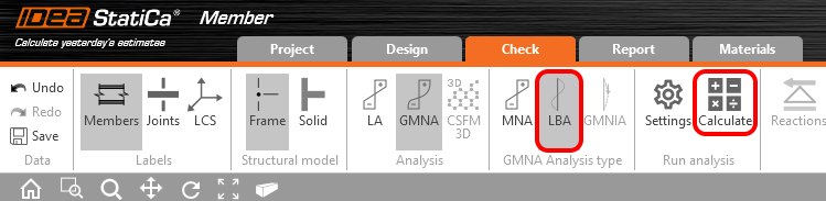
Führen Sie die LBA – Lineare Beulanalyse – durch.
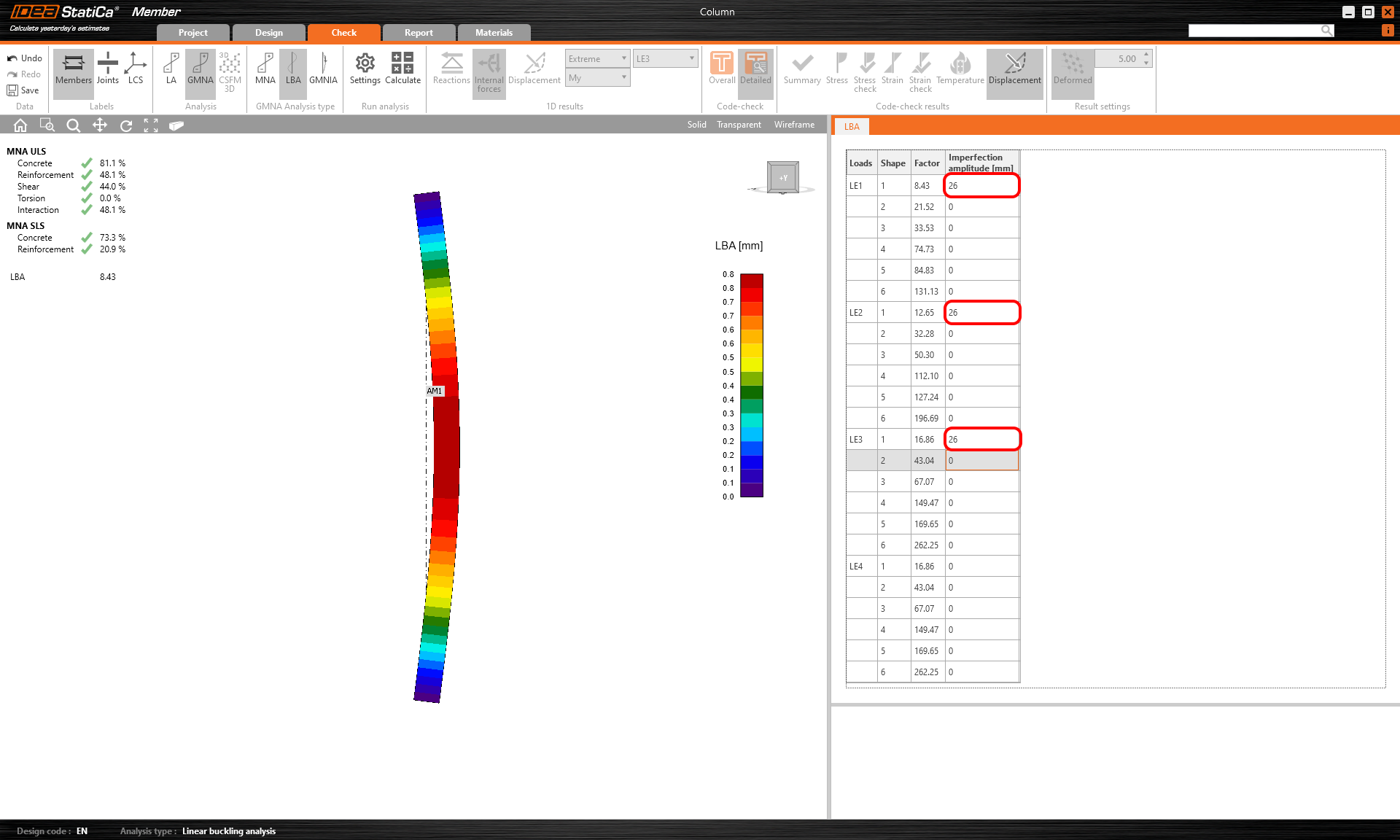
Wenn die Berechnung abgeschlossen ist, legen Sie die Imperfektionsamplitude fest. Lesen Sie den folgenden Artikel, um zu erfahren, wie diese einschließlich der zusätzlichen Amplitude infolge Kriechen einzustellen ist.
Geometrische Ersatzimperfektion gemäß EN 1992-1-1, Abschnitt 5.2 (9):
\[{{e}_{i}}={{l}_{0}}/400=8000/400=20mm\]
Die Amplitude einschließlich des Kriecheffekts beträgt 26 mm. Geben Sie diese nur für die Lastfälle LE1, LE2 und LE3 ein.
Starten Sie die GMNIA – Geometrisch und materiell nichtlineare Analyse mit Imperfektionen.

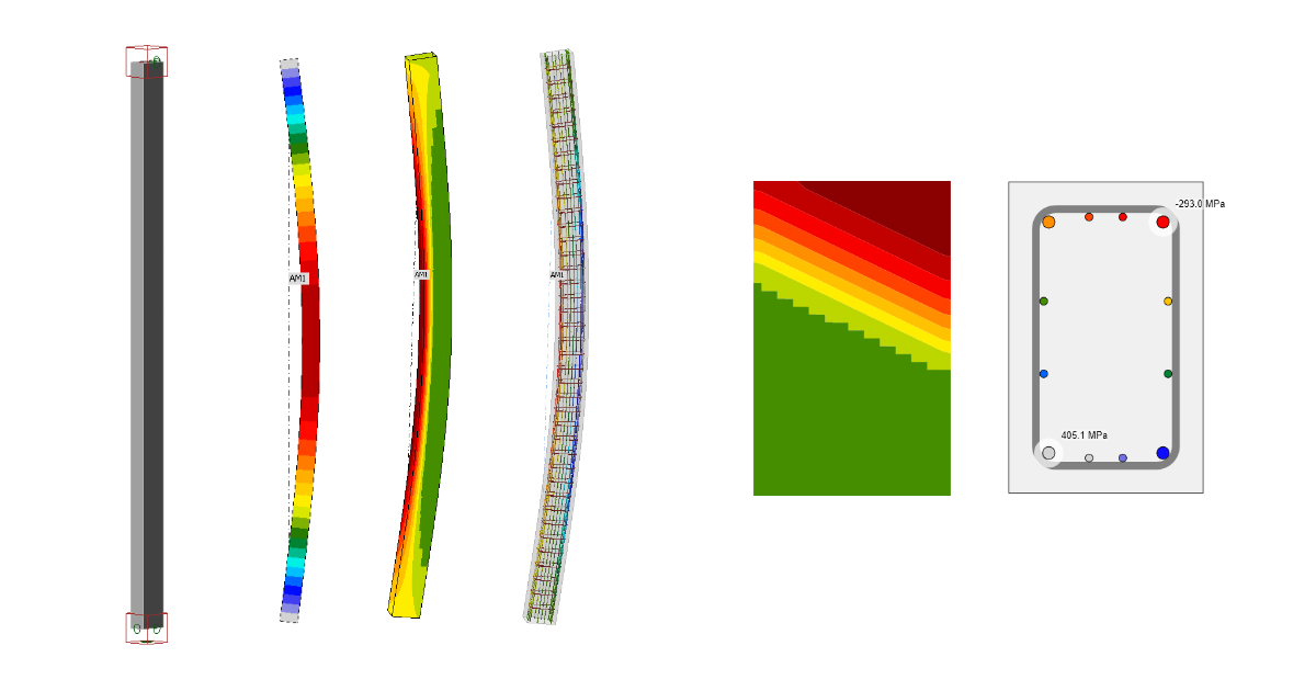
Dies war der letzte Analysetyp. Sie können die Ergebnisse ebenso wie bei der MNA überprüfen. Aufgrund des Theorie-II.-Ordnung-Effekts sind erhöhte Biegemomente erkennbar. Sie können die Spannungen im Beton und in der Bewehrung überprüfen. Vergessen Sie nicht, den maßgebenden Querschnitt auszuwählen.
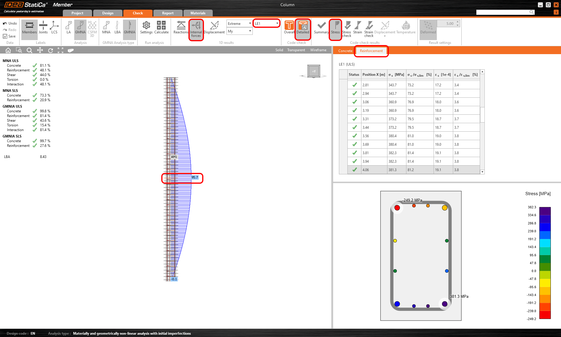
Nun können Sie die aus der GMNIA für LE2 erhaltenen Ergebnisse mit den Ergebnissen aus RCS vergleichen. Der Einfluss des Theorie-II.-Ordnung-Effekts ist deutlich erkennbar.
3 Bericht
Wechseln Sie zur Registerkarte „Bericht". Hier kann der Bericht gedruckt werden.

