Beschreibung
Ziel dieser Studie ist die Verifikation der komponentenbasierten Methode der finiten Elemente (CBFEM) eines Träger-Stützen-Knotens mit einem Stützensteg der Klasse 4 anhand der Komponentenmethode (CM).
Analytisches Modell
Das Bauteil Stützensteg im Schubfeld ist in Abschnitt 6.2.6.1 der EN 1993-1-8:2005 beschrieben. Das Bemessungsverfahren ist auf die Stegschlankheit d / tw ≤ 69 ε begrenzt. Stege mit höherer Schlankheit werden gemäß EN 1993-1-5:2006, Abschnitt 5 und Anhang A bemessen. Die Schubtragfähigkeit setzt sich aus der Schubbeulwiderstand des Stegfeldes und dem Widerstand des Rahmens aus Flanschen und Steifen, die das Feld umgeben, zusammen. Der Beulwiderstand des Stegfeldes basiert auf der kritischen Schubspannung
wobei σE die Euler-Beulspannung der Platte ist
Der Beulkoeffizient kτ wird gemäß EN 1993-1-5:2006, Anhang A.3 ermittelt.
Die Schlankheit des Stegfeldes beträgt
Der Abminderungsfaktor χw kann gemäß EN 1993-1-5:2006, Abschnitt 5.3 ermittelt werden.
Der Schubbeulwiderstand des Stegfeldes beträgt
Der Widerstand des Rahmens kann gemäß Abschnitt 6.2.6.1 der EN 1993-1-8:2005 bemessen werden.
Bemessungsmodell mit finiten Elementen
Das Bemessungsverfahren für schlanke Platten ist in Abschnitt 3.10 beschrieben. Die lineare Beulanalyse ist in der Software implementiert. Die Berechnung der Bemessungswiderstände erfolgt gemäß dem Bemessungsverfahren. FCBFEM wird vom Anwender interpoliert, bis ρ ∙ αult,k/γM1 gleich 1 ist.
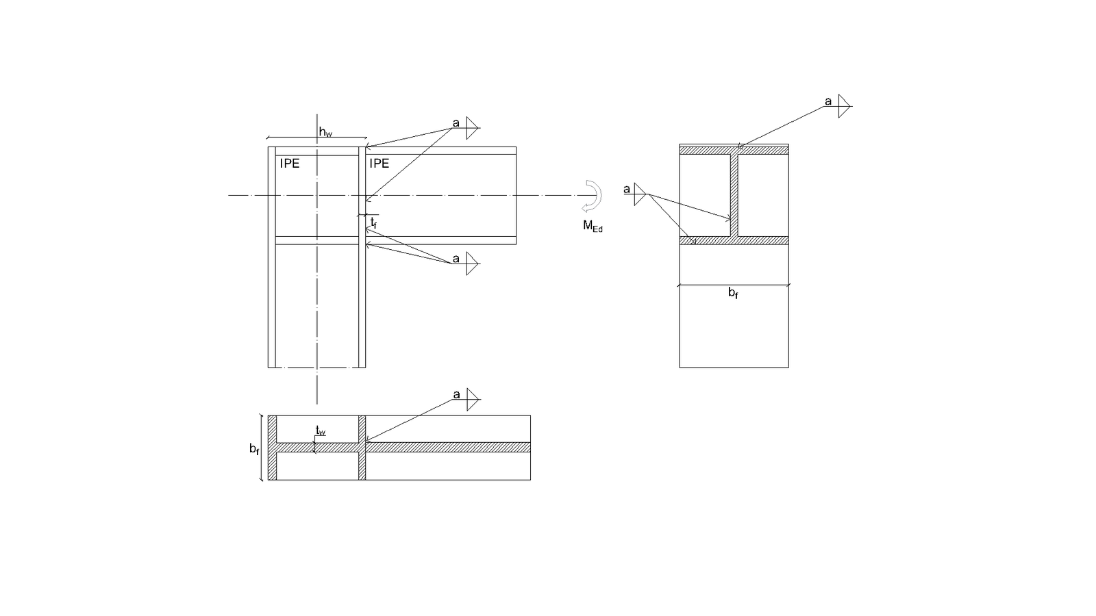
Es wird ein Träger-Stützen-Knoten mit einem schlanken Stützensteg untersucht. Die Höhe des Trägerstegs variiert, sodass sich die Breite des Stützenstegfeldes ändert. Die Geometrie der Beispiele ist in Tab. 6.2.1 beschrieben. Der Knoten wird durch ein Biegemoment belastet.
Tab. 6.2.1 Übersicht der Beispiele
| Beispiel | Stützenflansch | Stützensteg | Träger | Material | ||
| bf | tf | hw | tw | IPE | ||
| [mm] | [mm] | [mm] | [mm] | |||
| IPE400 | 250 | 10 | 820 | 4 | 400 | S235 |
| IPE 450 | 250 | 10 | 820 | 4 | 450 | S235 |
| IPE500 | 250 | 10 | 820 | 4 | 500 | S235 |
| IPE 550 | 250 | 10 | 820 | 4 | 550 | S235 |
| IPE600 | 250 | 10 | 820 | 4 | 600 | S235 |
Globales Verhalten und Verifikation
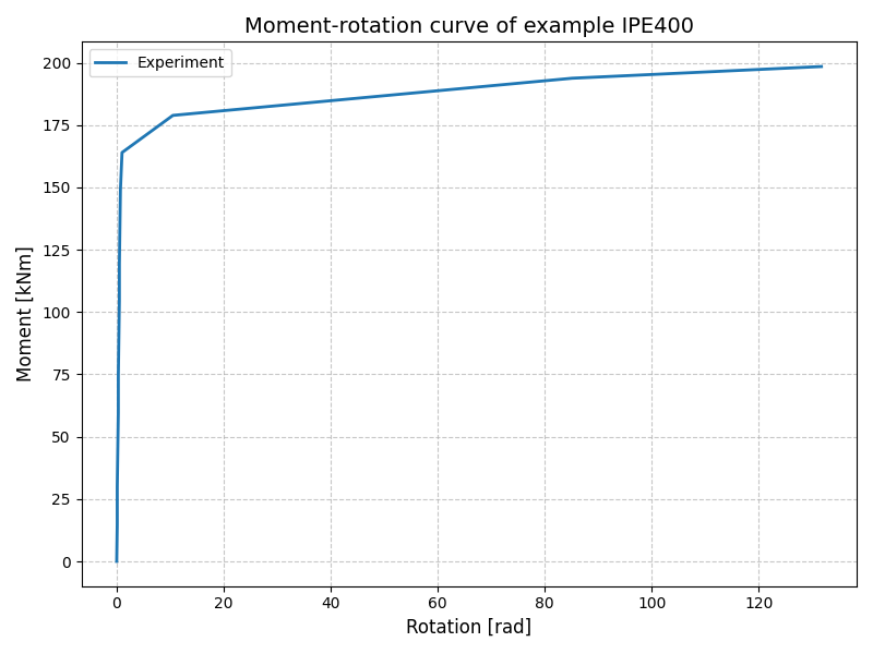
Das globale Verhalten eines Träger-Stützen-Knotens mit schlankem Stützensteg, dargestellt durch das Momenten-Rotations-Diagramm im CBFEM-Modell, ist in Bild 6.2.2 gezeigt. Das Augenmerk liegt auf den wesentlichen Kenngrößen: Bemessungswiderstand und kritische Last. Das Diagramm wird durch einen Punkt ergänzt, an dem die Fließgrenze erreicht wird, sowie durch den Widerstand bei 5 % plastischer Dehnung.
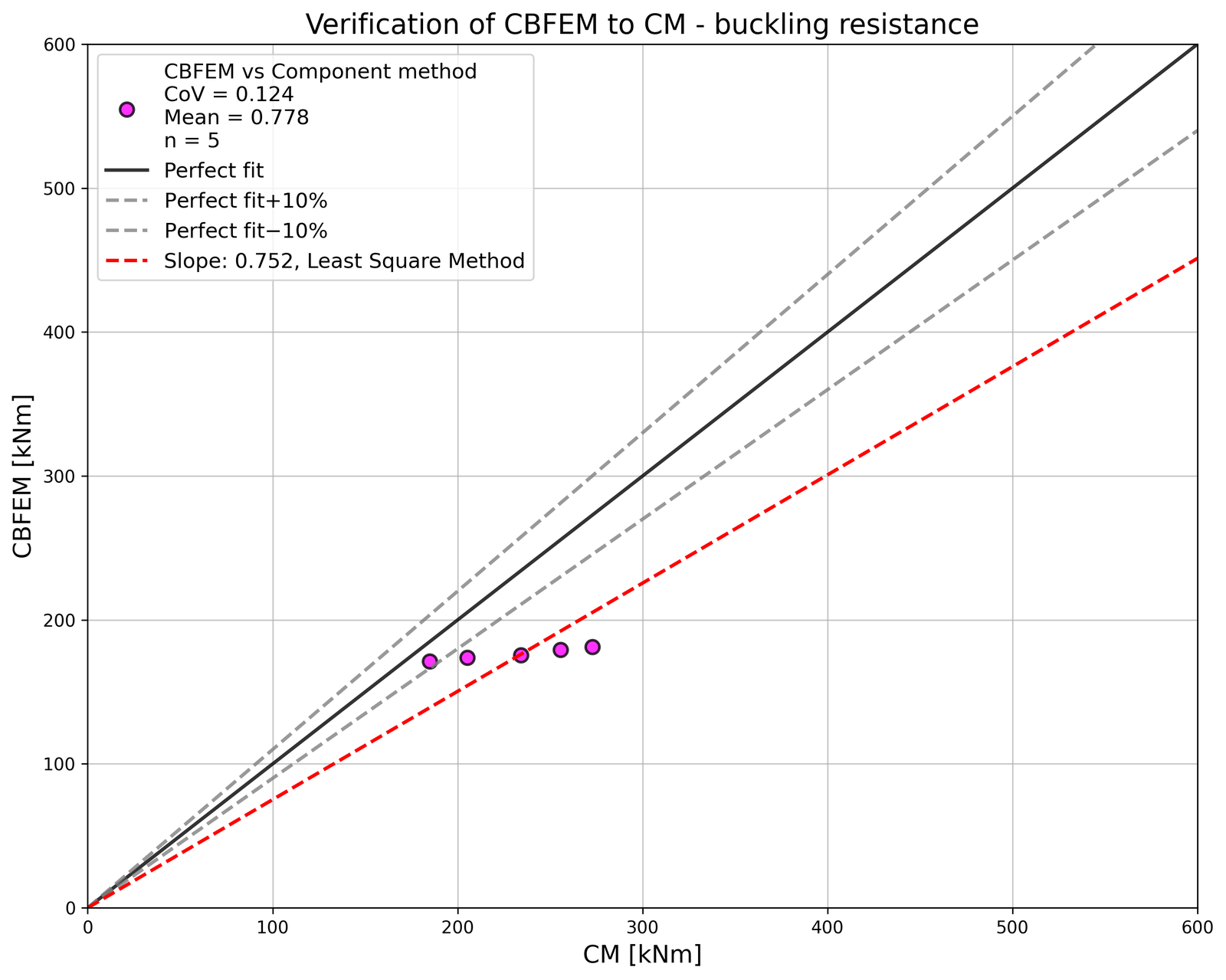
Verifikation des Widerstands
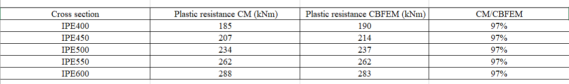
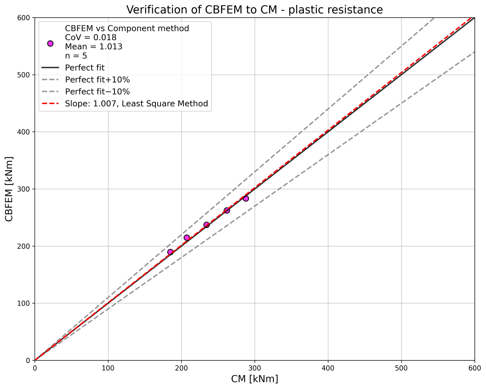
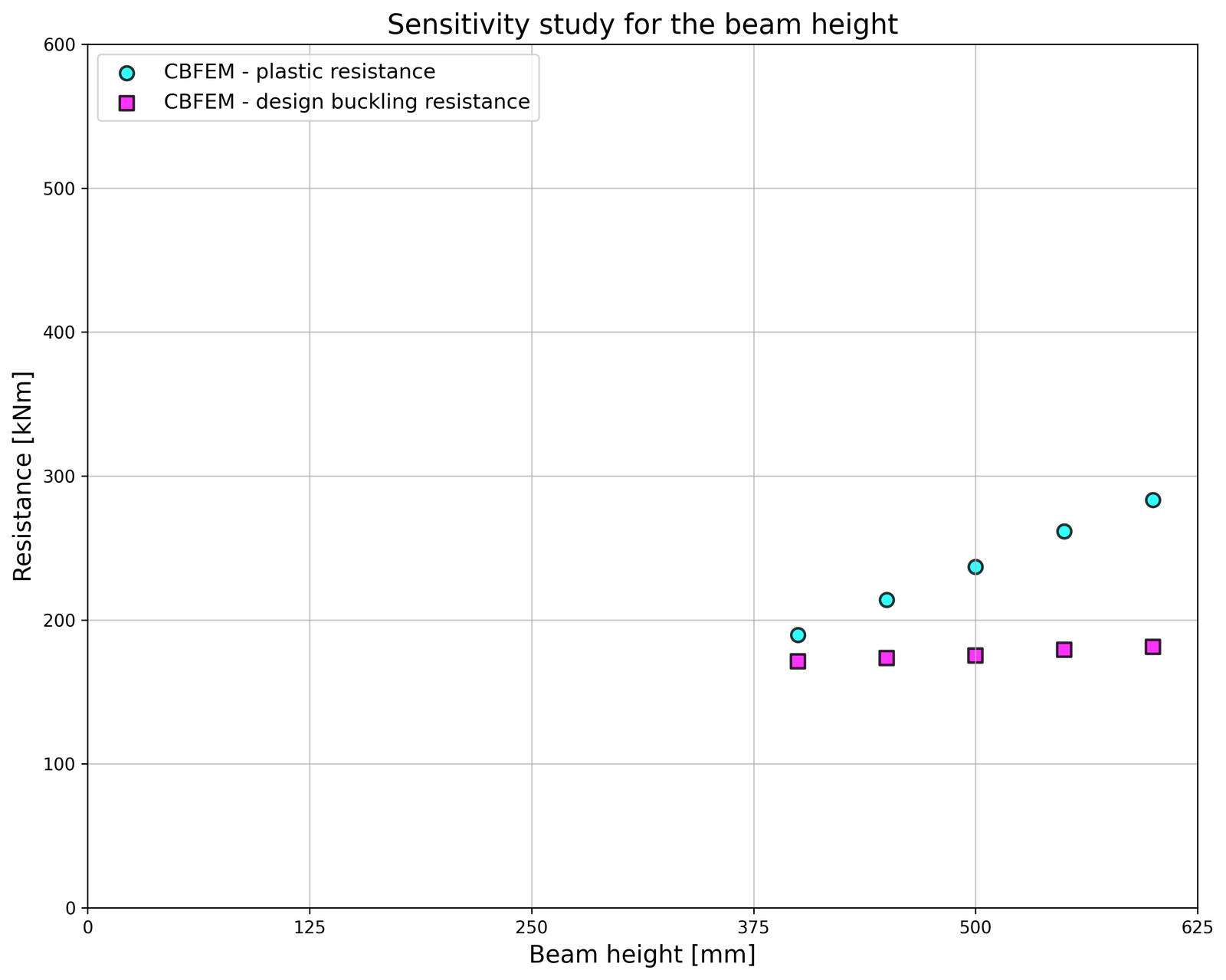
Der mit CBFEM berechnete Bemessungswiderstand wird mit der CM verglichen. Der Vergleich konzentriert sich auf den plastischen Widerstand. Die Ergebnisse sind in Tab. 6.2.2a zusammengestellt. Bild 6.2.2a zeigt die Unterschiede zwischen den beiden Berechnungsverfahren. Tabelle 6.2.2b enthält die Daten zum Bemessungsbeulwiderstand. Tabelle 6.2.2c und Bild 6.2.3c zeigen die Unterschiede zwischen den beiden Berechnungsverfahren bei der Ermittlung des Beulwiderstands. Das Diagramm in Bild 6.2.3c zeigt den Einfluss der Trägerhöhe auf die Widerstände und kritischen Lasten der untersuchten Beispiele.
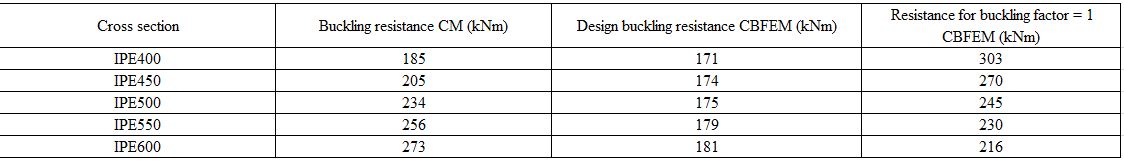
Tab. 6.2.2a Plastische Widerstände von CM und CBFEM
Tab. 6.2.2b Bemessungsbeulwiderstand

Tab. 6.2.2c Beulwiderstände von CM und CBFEM
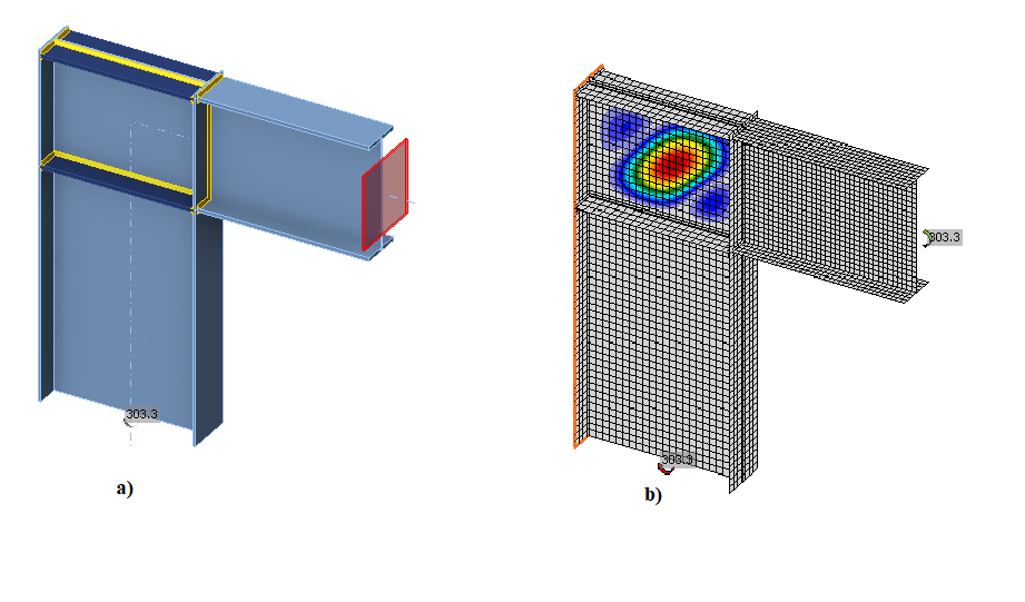
Die Ergebnisse zeigen eine gute Übereinstimmung bei der kritischen Last und dem Bemessungswiderstand. Das CBFEM-Modell des Knotens mit einem Träger IPE600 ist in Bild 6.2.3a dargestellt. Die erste Beulform des Knotens ist in Bild 6.2.3b gezeigt.
Verifikationsstudien haben die Genauigkeit des CBFEM-Modells für die Vorhersage des Verhaltens des Stützenstegfeldes bestätigt. Die Ergebnisse des CBFEM werden mit den Ergebnissen der CM verglichen. Beide Verfahren prognostizieren ein ähnliches globales Verhalten des Knotens.
Benchmark-Beispiel
Eingaben
Träger
- Stahl S235
- IPE600
Stütze
- Stahl S235
- Flanschdicke tf = 10 mm
- Flanschbreite bf = 250 mm
- Stegdicke tw = 4 mm
- Steghöhe hw = 800 mm
- Querschnittshöhe h = 820 mm
- Überstand über Trägeroberkante 20 mm
Stegsteife
- Stahl S235
- Steifedicke tw = 19 mm
- Steifebreite hw = 250 mm
- Schweißnähte aw,stiff = 10 mm
- Steifen gegenüber Ober- und Unterflansch
Normeinstellungen – Modell und Netz
- Anzahl der Elemente am größten Bauteilsteg oder -flansch: 24
Ausgaben
- Last bei 5 % plastischer Dehnung Mult,k = 283 kNm
- Bemessungswiderstand MCBFEM = 181 kNm
- Kritischer Beulfaktor (für M = 189 kNm) αcr = 1,19
- Lastfaktor bei 5 % plastischer Dehnung αult,k = Mult,k / MCBFEM = 283/181 = 1,56
Literatur
EN 1993-1-5, Eurocode 3, Bemessung und Konstruktion von Stahlbauten – Teil 1-5: Plattenförmige Bauteile, CEN, Brüssel, 2005.
EN 1993-1-8, Eurocode 3, Bemessung und Konstruktion von Stahlbauten – Teil 1-8: Bemessung von Anschlüssen, CEN, Brüssel, 2005.
Kuříková M., Wald F., Kabeláč J. Design of slender compressed plates in structural steel joints by component based finite element method, in SDSS 2019: International Colloquium on Stability and Ductility of Steel Structures, Prag, 2019.