Members that have non-zero warping constant, \(I_w\), and are loaded in a different way than by two identical torsion moments at their ends, warp when subjected to torsion.
Members in IDEA StatiCa Connection have their manufacturing operations and then behind these by default 1.25*h of shell elements + 4*h of condensed elements; see Automatic member length article. So their length is actually not negligible but reaches to about a third of a typical steel member span.
When torsion is applied, and this may be either directly by entering Mx or applying a shear force to an unsymmetrical member, e.g. channel or angle, warping stresses develop.
Torsion causes:
- St. Venant torsion, \(T_t\)
- Warping torsion, \(T_w\)
- Bimoment, \(B\)
And these, in turn, cause stresses:
- Shear stress due to St. Venant torsion, \(\tau_{t}\)
- Shear stress due to warping torsion, \(\tau_w\)
- Normal stress due to bimoment, \(\sigma_w\)
The forces may be determined by solving differential equation:
\[EI_w\varphi^{IV}-GI_t\varphi^{II}=m\]
where:
- \(E\) – modulus of elasticity in tension and compression
- \(G\) – modulus of elasticity in shear
- \(I_w\) – warping constant
- \(I_t\) – torsion constant
- \(\varphi\) – rotation
- \(m\) – torsion moment
The solutions are known for ideal boundary conditions, e.g. fixed end or free end.
The upper bound of normal stress due to bimoment for IDEA StatiCa Connection members is the condition of fixed end and a free end where the load (torsion) is applied.
For this condition:
\[T_t=M \left ( 1-\frac{{\cosh} K_t (1-x/L)}{{\cosh}K_t} \right )\]
\[T_w = M \frac{{\cosh} K_t (1-x/L)}{{\cosh} K_t}\]
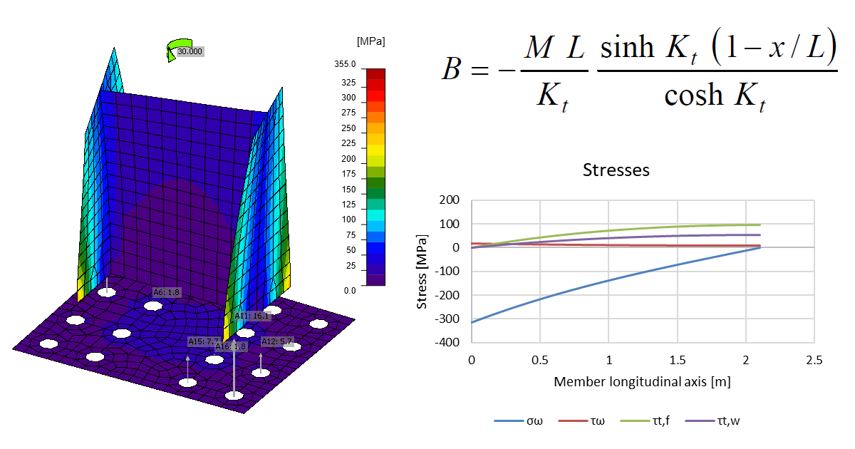
\[B=-\frac{ML}{K_t}\frac{{\sinh} K_t (1-x/L)}{{\cosh} K_t}\]
where:
- \(M\) – torsion moment applied at the end of member (Mx set in IDEA StatiCa Connection, or shear force V times distance between center of shear and center of gravity)
- \(K_t = L \sqrt{\frac{GI_t}{EI_w}}\)
- \(L\) – member (cantilever) length
Here is an example of a really stiff connection:
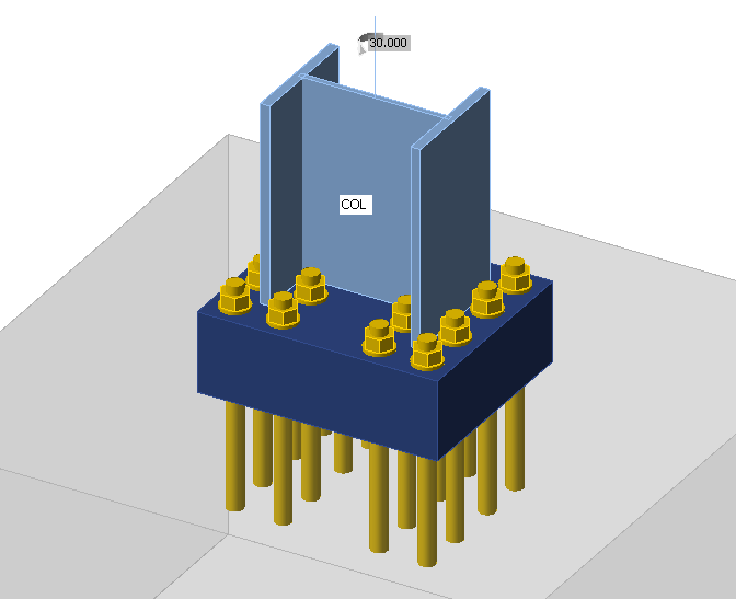
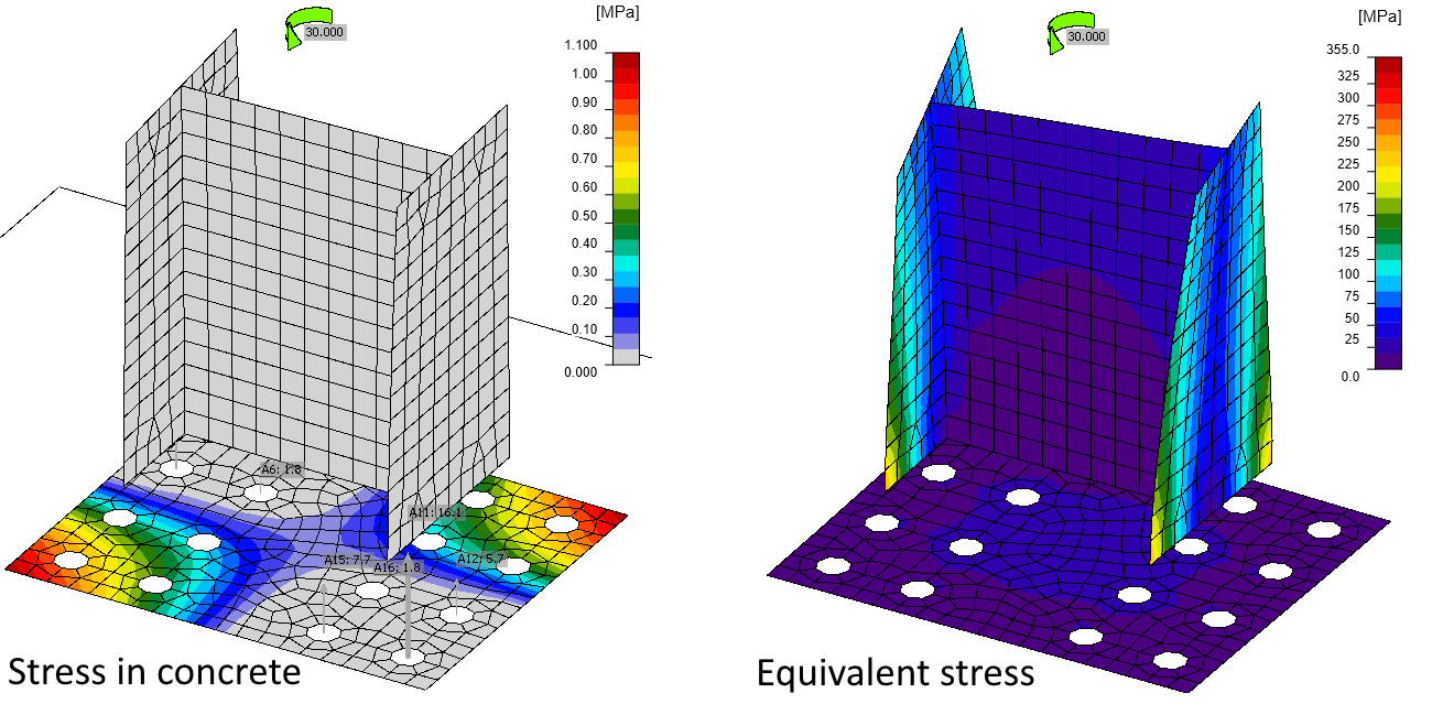
The column is loaded by torsion moment \(M_x = 30\,\textrm{kNm}\). Although, the base plate is really thick, it still slightly deforms due to column warping. This causes tensile forces in anchors and compressive stress in concrete. That means the warping restraint is still not perfect. However, we cannot expect anything like this in the real world.
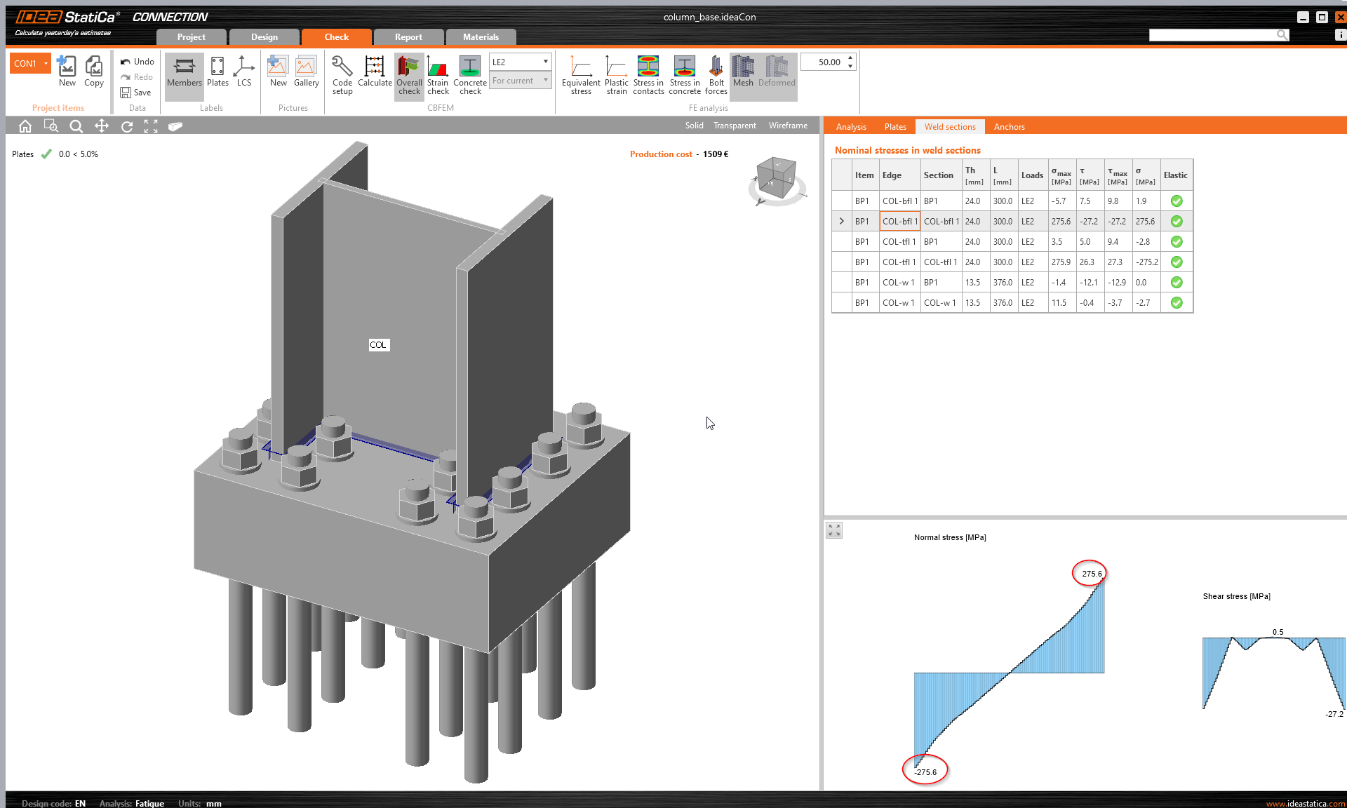
Using fatigue analysis, we can plot normal and shear stresses near the butt weld (at a distance 0.5 times weld throat thickness):
Let's compare the stresses with an analytical solution. Using the formulas shown above, the forces are:
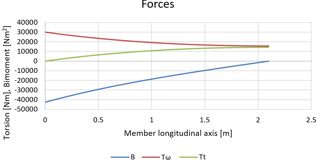
And corresponding stresses at the column flange can be calculated:
\[\tau_t=T_t \frac{t_f}{I_t}\]
\[\tau_w= T_w \frac{S_{\omega,max}}{I_w t_f} \]
\[\sigma_w=B \frac{\omega}{I_w}\]
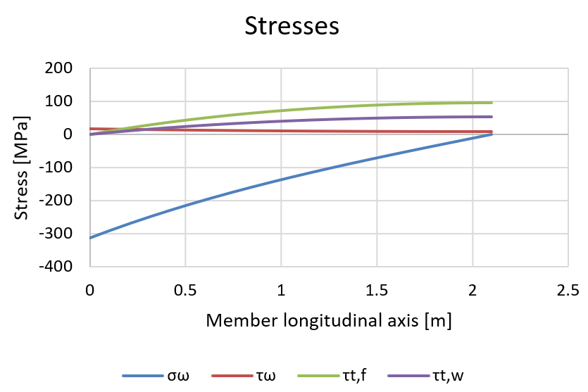
The peak normal stress caused by warping at the location of the base plate (Member longitudinal axis = 0 in graphs) reaches 314 MPa, which is slightly higher than the results we get in IDEA StatiCa. This difference is caused by imperfect warping restraint. The shear stresses at member connection (in this case column base) are negligible.
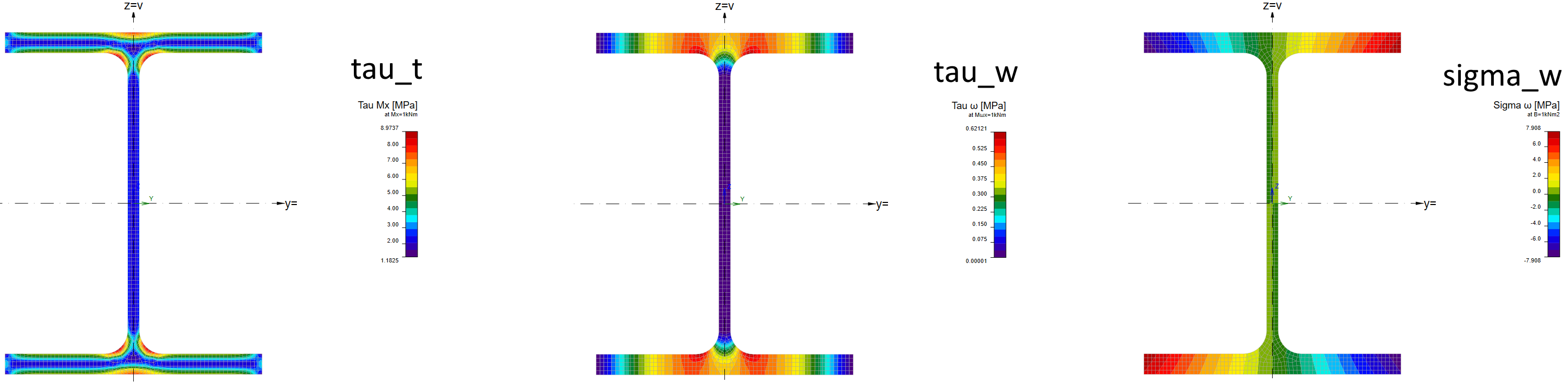
The stress distribution along the cross-section due to torsion and warping can be seen in the General cross-section editor:
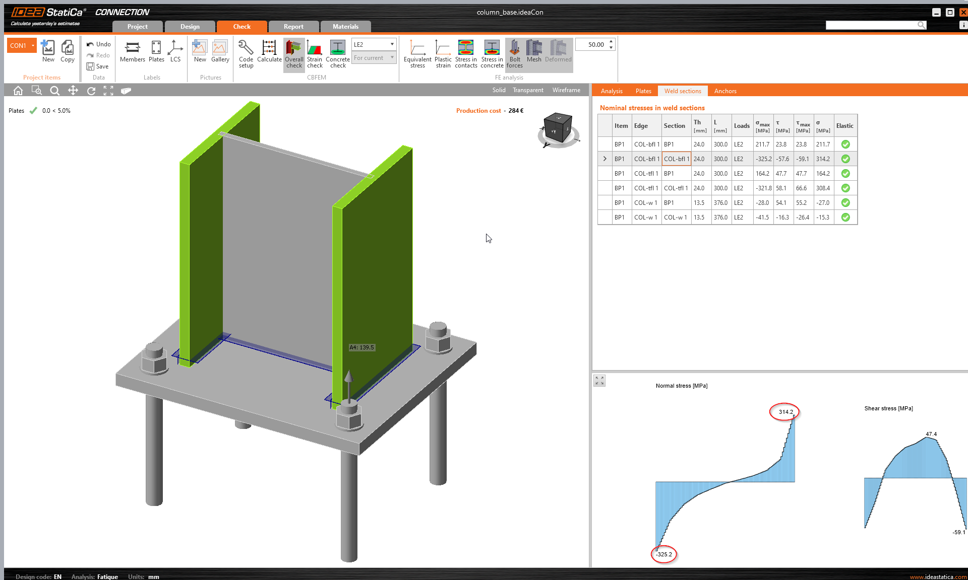
A real-life example may be more tricky to explain. Let's change base plate thickness to 30 mm and use just four anchors M36 8.8:
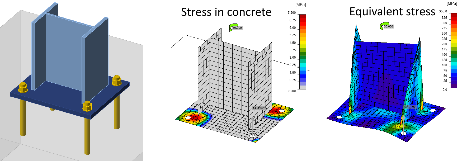
Now, the base plate deforms significantly, the stress in concrete is not negligible and force in anchor is actually huge, nearly 140 kN (compare to \(N_{Rd,s} = 370.4\, \textrm{kN}\) determined by EN 1992-4). Normal stresses due to warping are no longer linear as according to the analytical solution due to base plate deformation. A bit surprisingly, the peak stress 314 MPa is actually equal to the analytical solution.
Conclusion
Engineers tend to ignore torsion effects, especially warping, or avoid it, e.g. by using closed sections. Note that software using 1D elements usually have six degrees of freedom (3 translations, 3 rotations), and to capture warping, they would need a seventh. 1D elements with seven degrees of freedom are available e.g. in LTBeam or Consteel. Even then, it is difficult to determine how warping is transferred through connections from one member to another. Nonetheless, warping is a real phenomenon and open sections are very susceptible to its effects.
Be careful when applying torsion on members with open cross-section. When this member is failing in IDEA StatiCa Connection, it should be a red flag for an engineer. Torsion including warping should be evaluated in member design, e.g. using IDEA StatiCa Member with real member length and forces applied at correct locations.