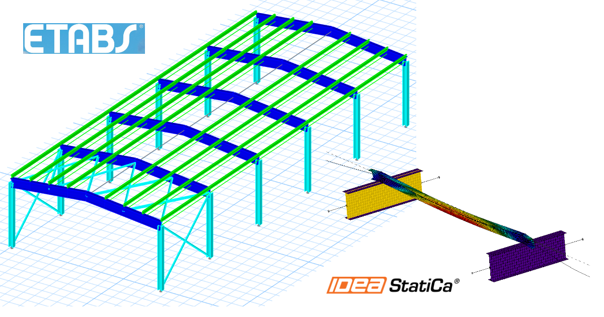
ETABS BIM link for steel Member design (AISC)
How to activate the link
- Download and install the latest version of IDEA StatiCa
- Make sure that you are using a supported version of your FEA/BIM solution
IDEA StatiCa integrates BIM links into your FEA/BIM solutions during its installation. You can check the status and activate more BIM links for software installed after in the BIM link installer.
Please note that some FEA solutions require additional steps to fully activate their BIM link to IDEA StatiCa.
Open IDEA StatiCa and navigate to the BIM tab and open the BIM link installer (Activate your BIM link...).
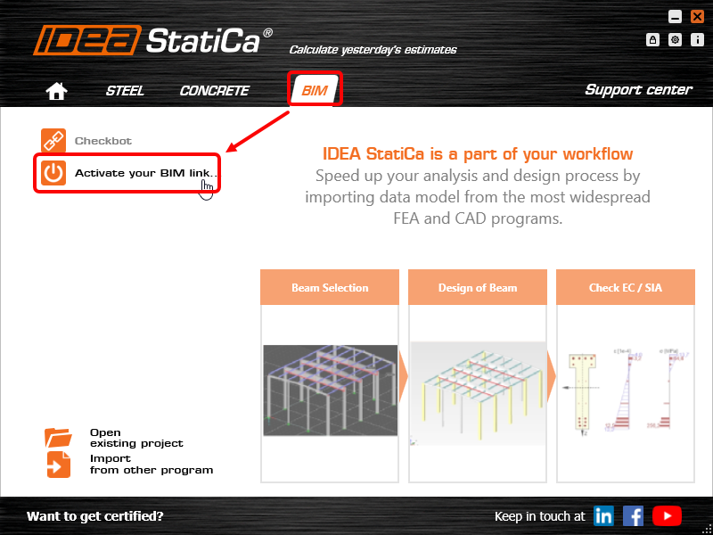
A notification "Do you want to allow this app to make changes to your device?" may appear, if so, please confirm with the Yes button.
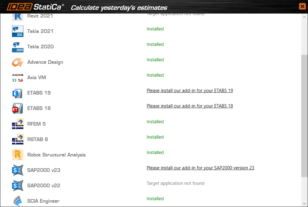
The BIM link for the selected software (if found) is installed. The screen also tells you the status of other BIM links that may have already been installed.
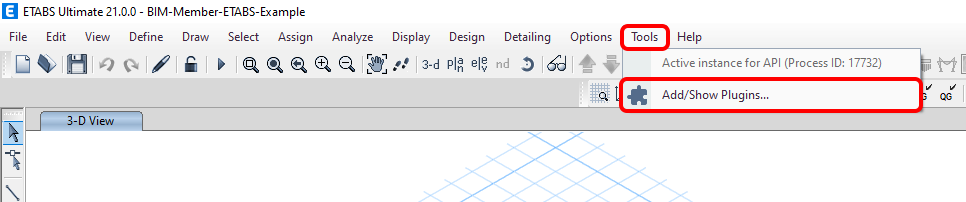
There are some additional manual steps required in ETABS to finish the integration procedure:
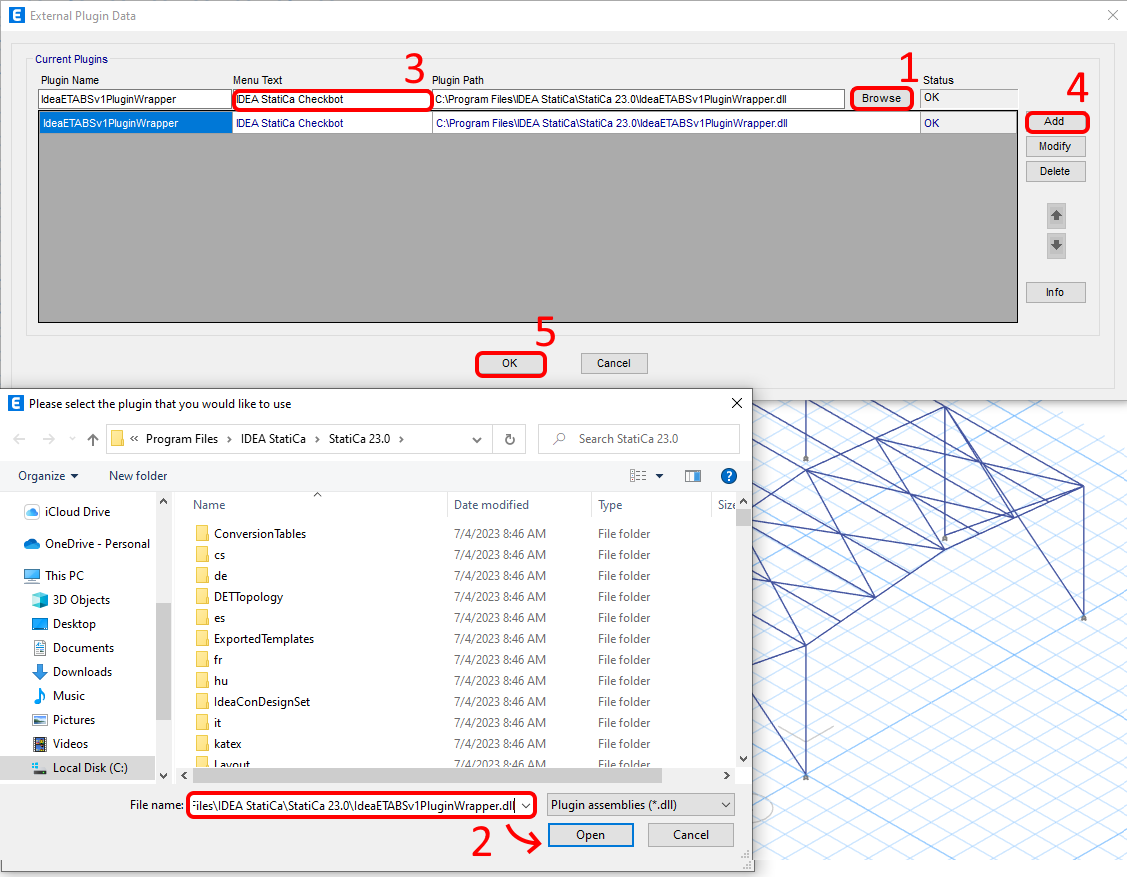
Start ETABS and click Tools > Add/Show Plugins to open the Plugin Manager dialog. This option lets you install add-ins (programs) to the appropriate places in the ETABS menu.
Browse for:
C:\Program Files\IDEA StatiCa\StatiCa 23.0\IdeaETABSv1PluginWrapper.dll
(for older versions of IDEA StatiCa C:\Program Files\IDEA StatiCa\StatiCa 22.1\ETABSv18PlugIn_IDEAStatiCa.dll).
You can edit the Plugin's name displayed in your dropdown menu as IDEA StatiCa Checkbot, then click Add.
How to use the link
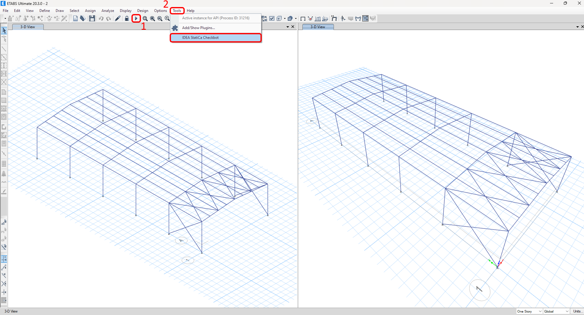
Download the attached project, open it in ETABS, and run the calculation to get the internal forces over the structure.
The BIM link is already integrated. It is in the top ribbon under Tools -> IDEA StatiCa Checkbot.
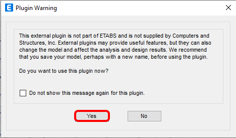
You will then see a warning about using the plugin; please confirm to continue successfully.
Select the New option with project type Steel and design code AISC LRFD 360-22. Then select Create Project.
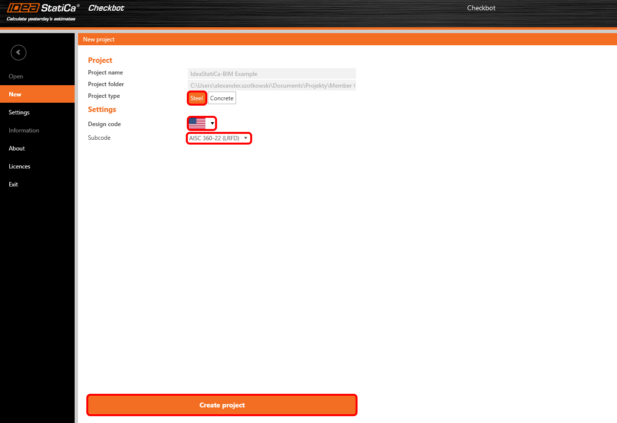
The new Checkbot project is ready to import members from ETABS.
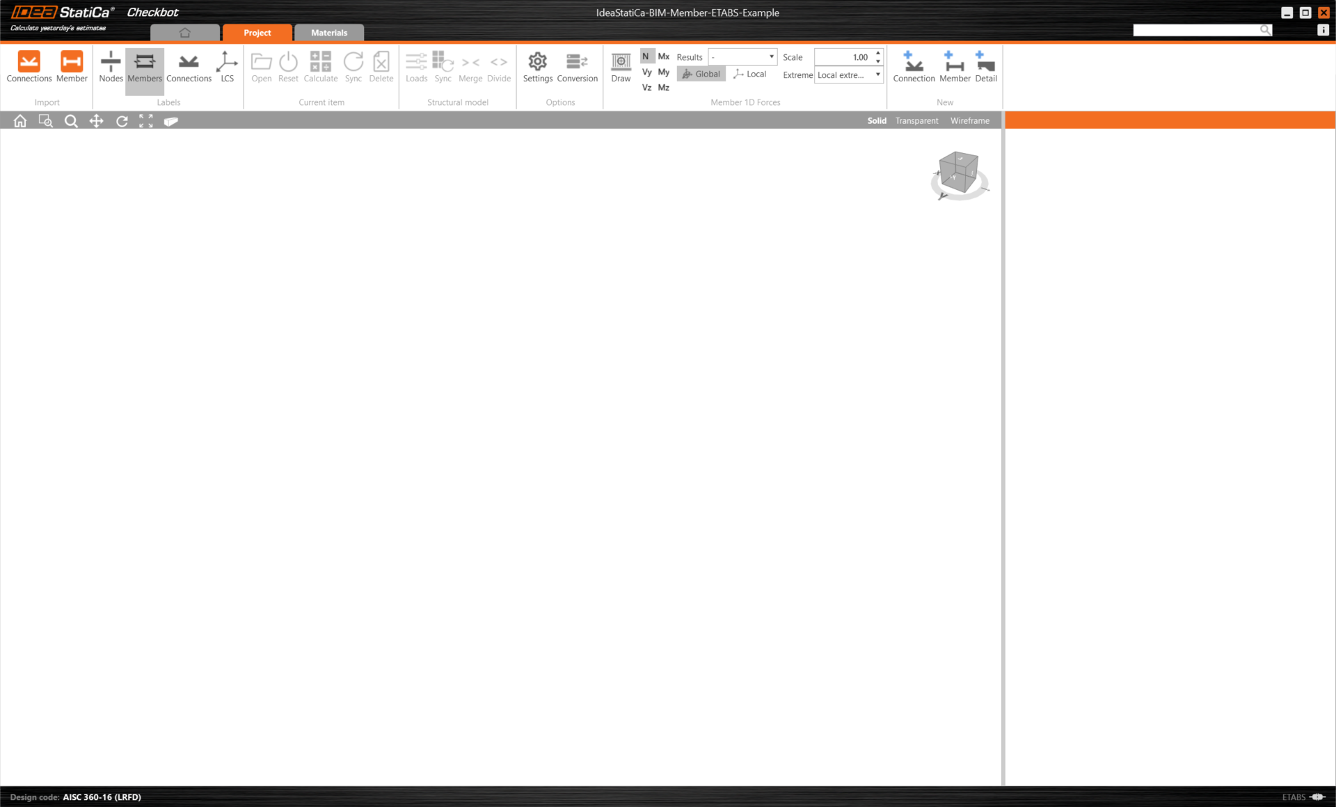
In ETABS, select one of the inside members. In the bottom left corner of the screen, you will see how many elements you have selected and how many will be imported to Checkbot.
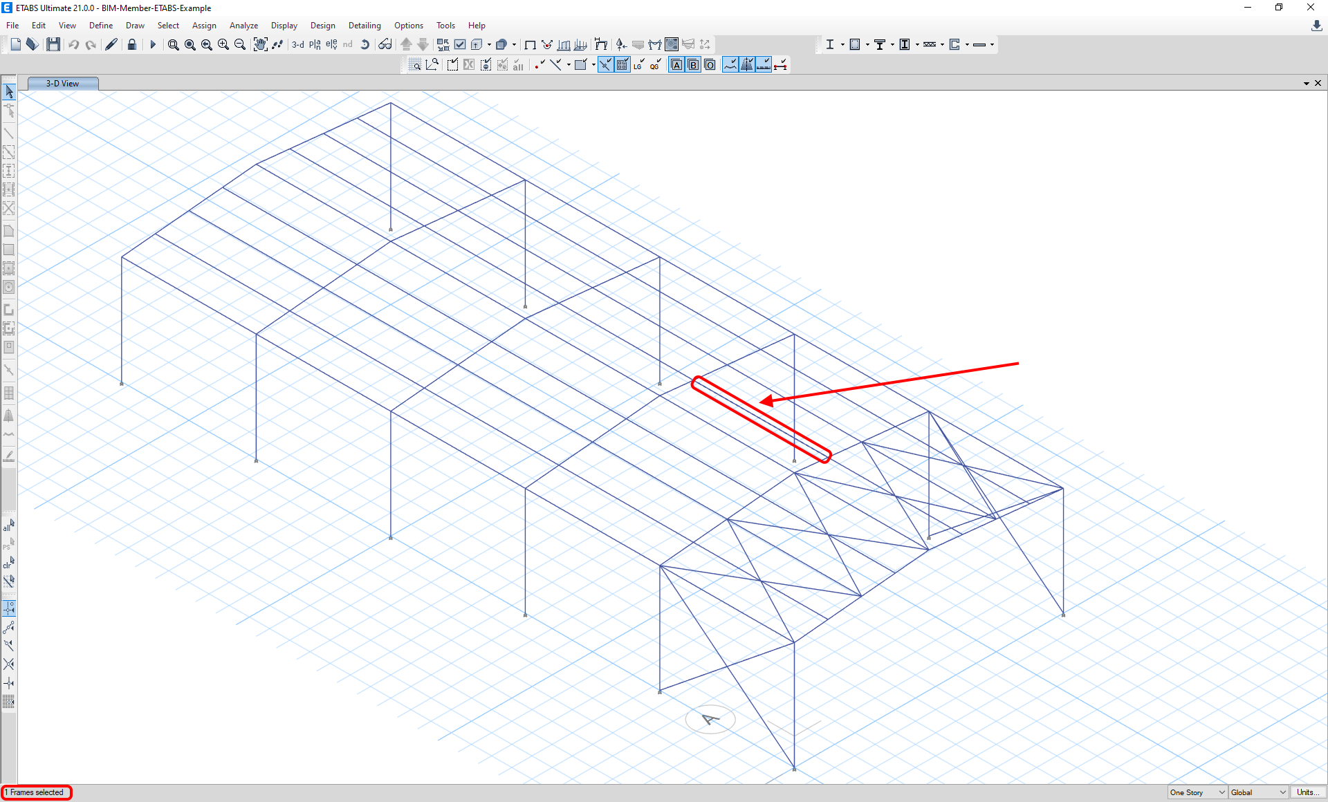
Import
Then in Checkbot select Member.
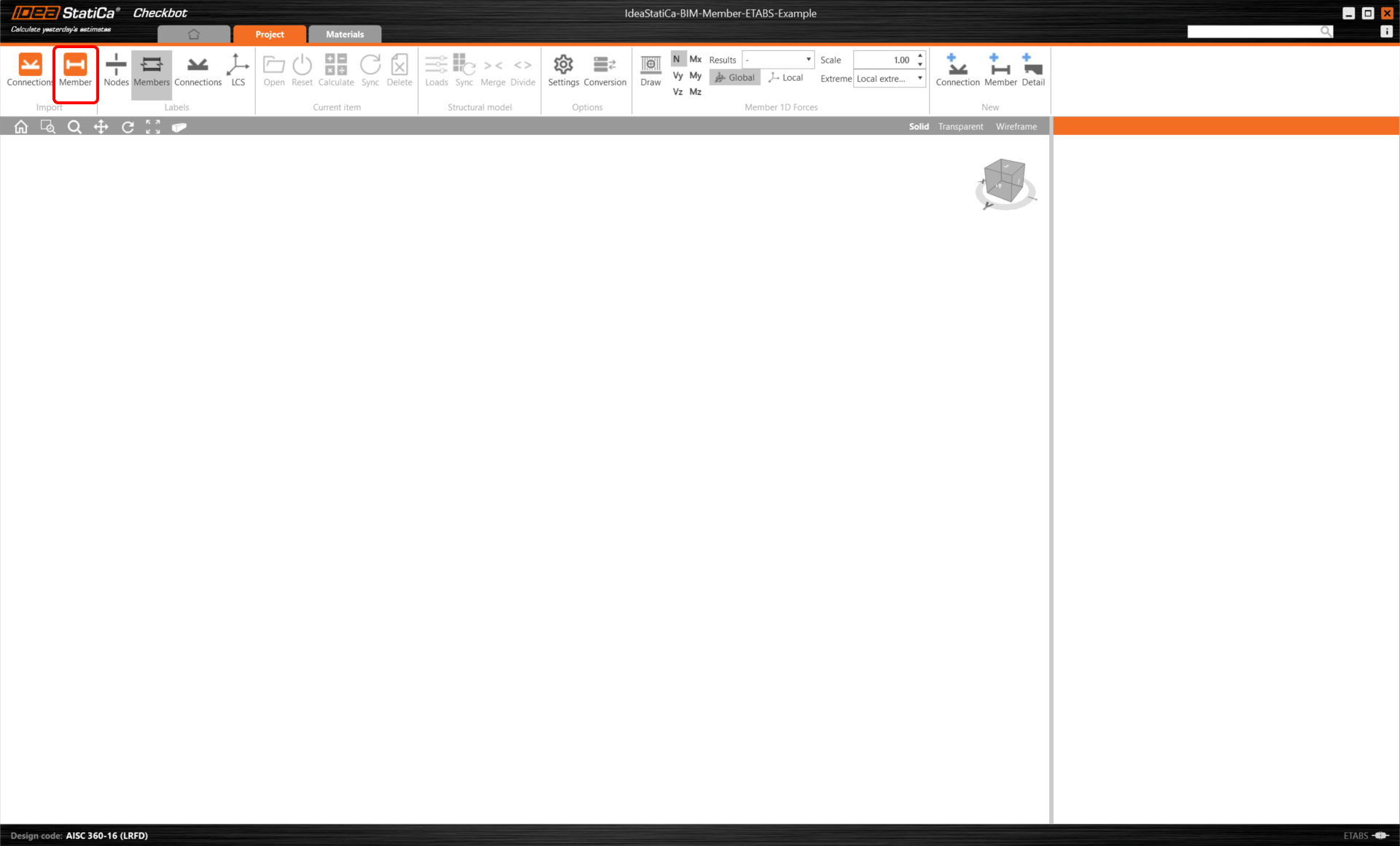
This will import the beam and its load effects into Checkbot - with the same coordinates, orientations, and section sizes as per the FEA/BIM model.
Please note that your node and member numbering might be different.
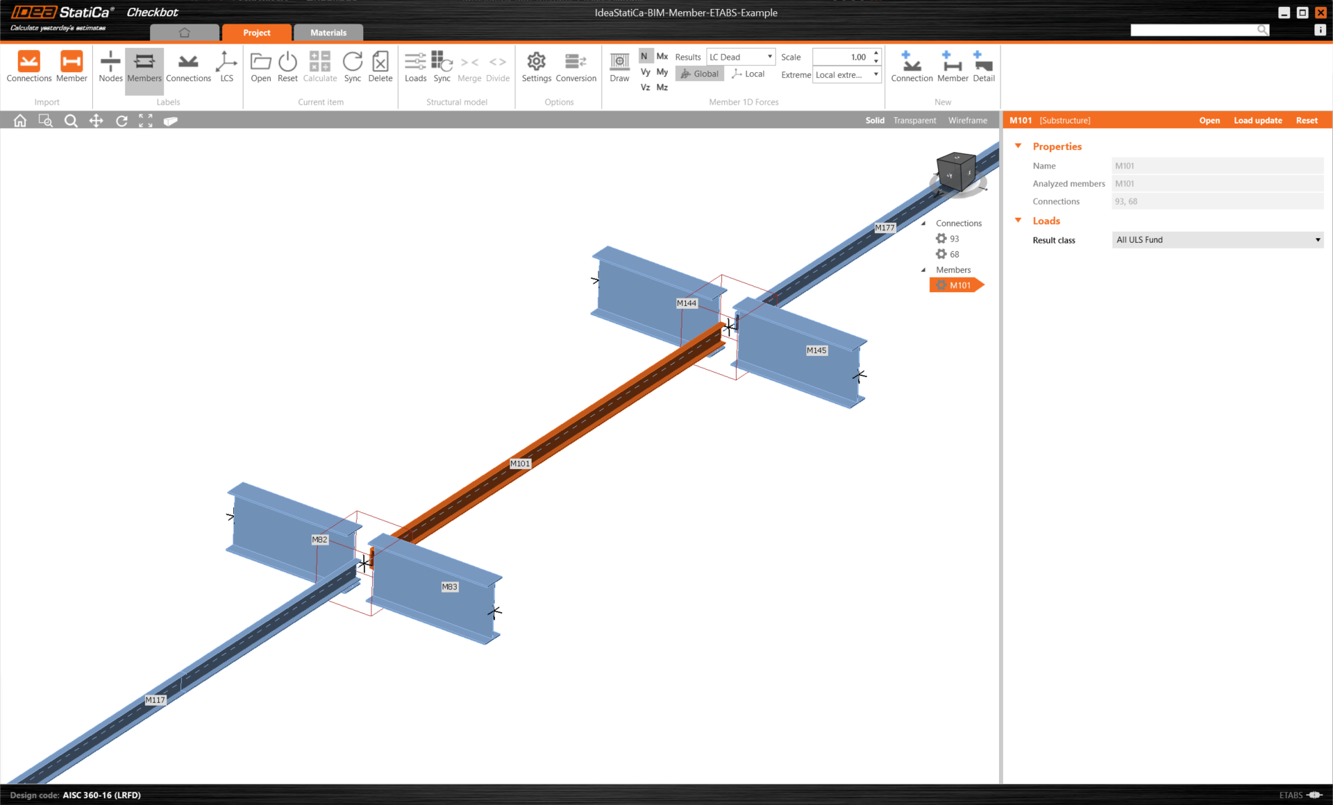
As you can see, the selected member with all related members was imported.
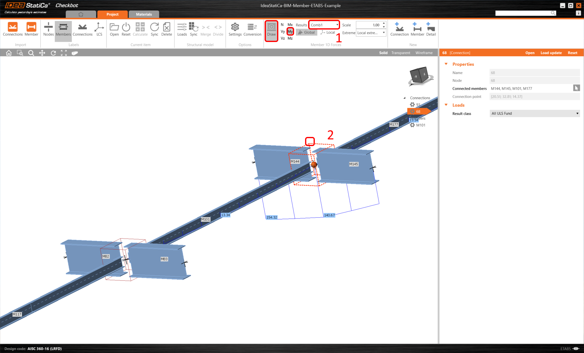
You can check the internal forces. Select Draw, then the desired internal force and combination, then left-click on the connection box, and follow the steps below in the picture.
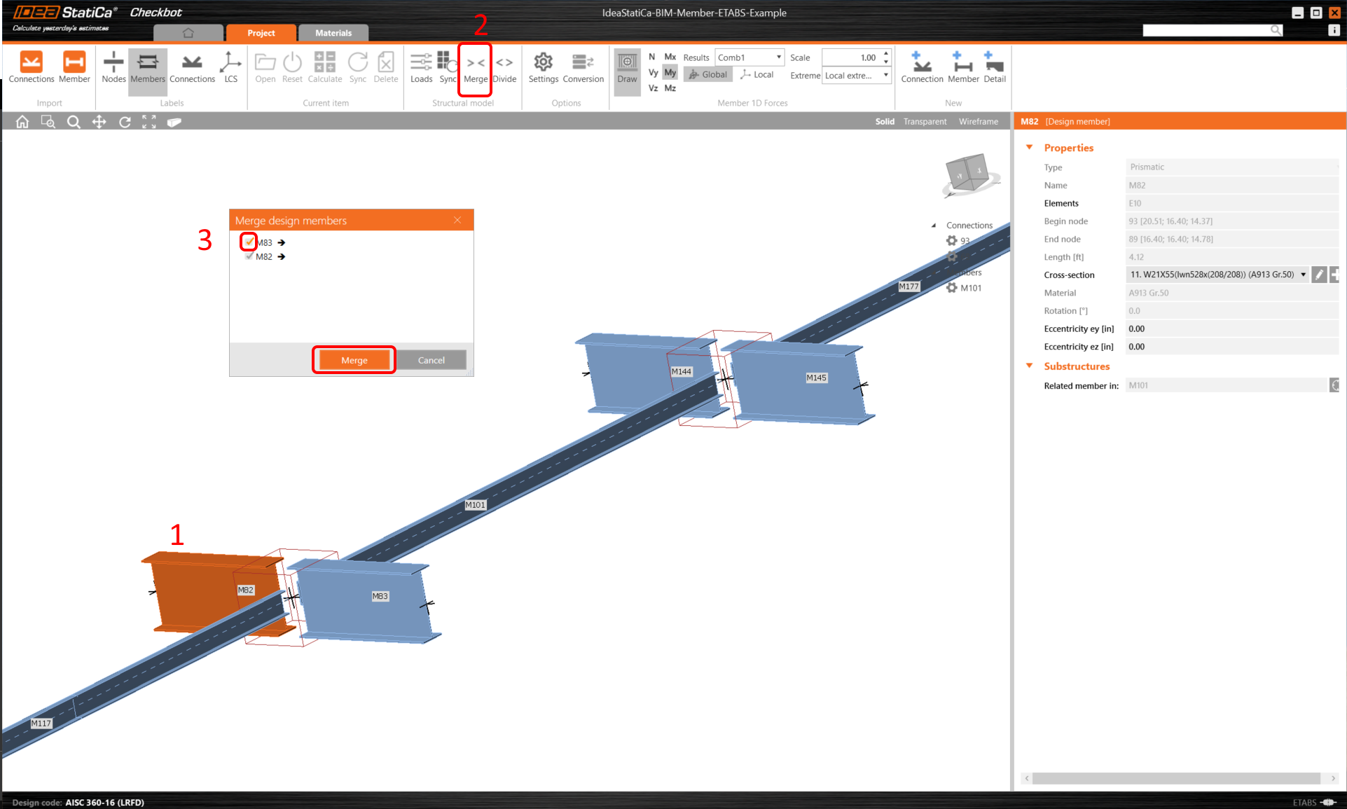
Elements can be merged together directly in Checkbot, then in the Member application, they will be a single continuous element.
Merge both perpendicular related members. Left-click the I-profile M-82, select Merge operation, then tick the M83 box in the merge design window, and follow the steps as shown in the picture.
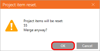
In this window, you will see an informative alert about the operation that will occur, accept it.
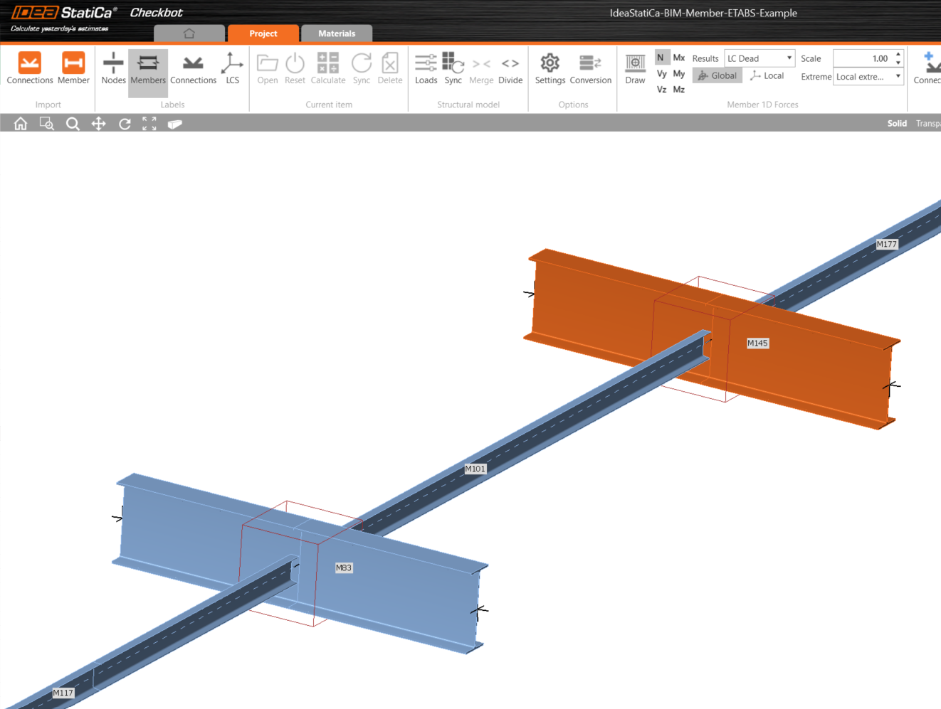
Make the same merging action for another group of I-profile. After changes, our model should look as in the following picture.
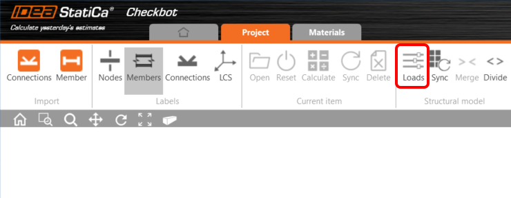
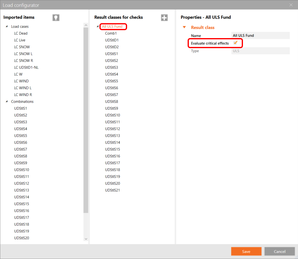
You can control what load case or combination will be loaded to the Member application by clicking on Loads and managing Result classes for checks.
Also by default, the Evaluate critical effects function is turned on, which filters out the load cases with the worst effect. It serves to speed up the calculation, it can also be turned off in the Loads setting.
As written in the article Known limitations, the eccentricity of the beams is not taken over into IDEA StatiCa. That is why we have manually set the purlins to the proper position. The value is calculated as 1/2 (20,8 + 7) = 13,9 in.
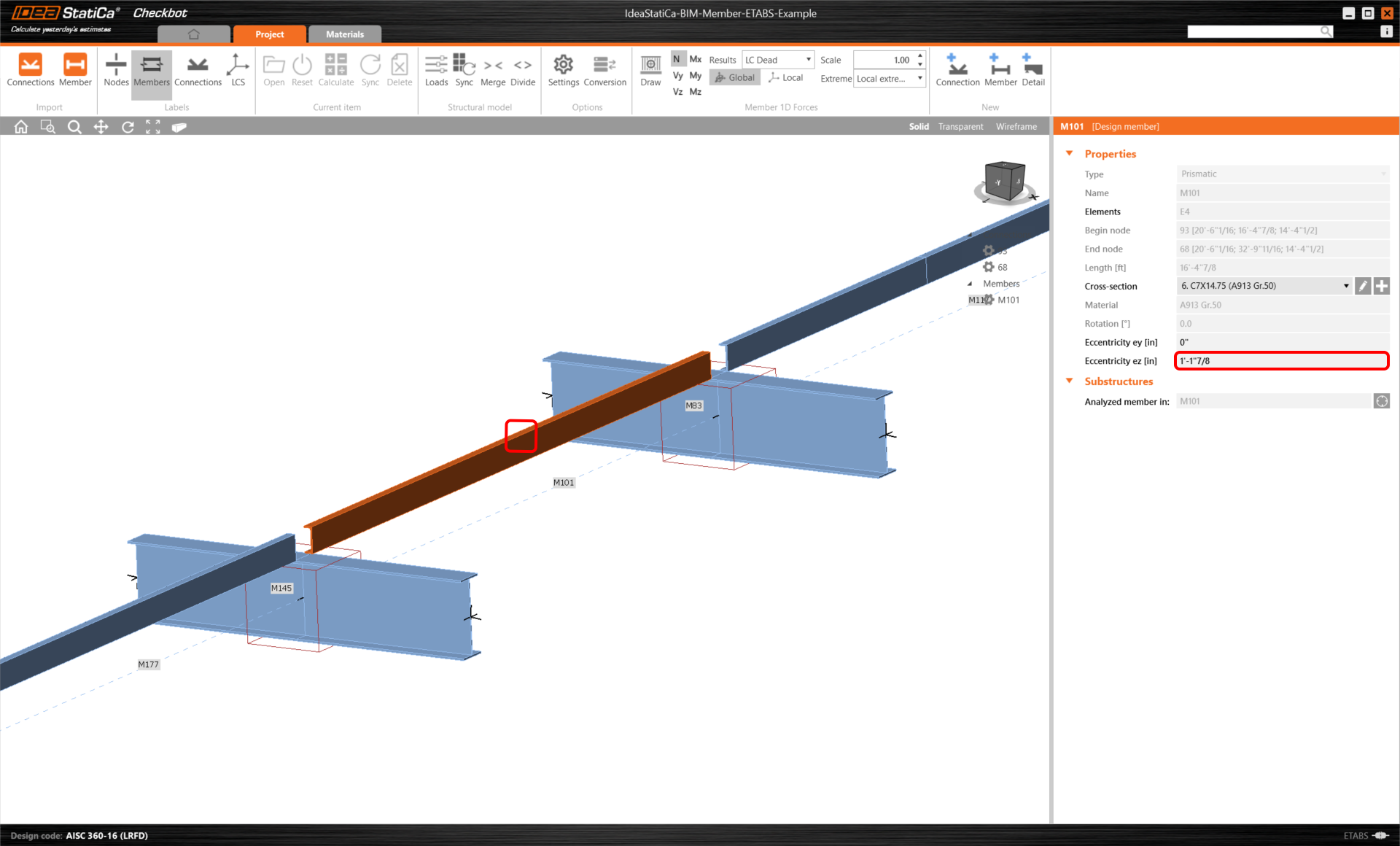
This value must also be set to the related members left and right of the analyzed beam.
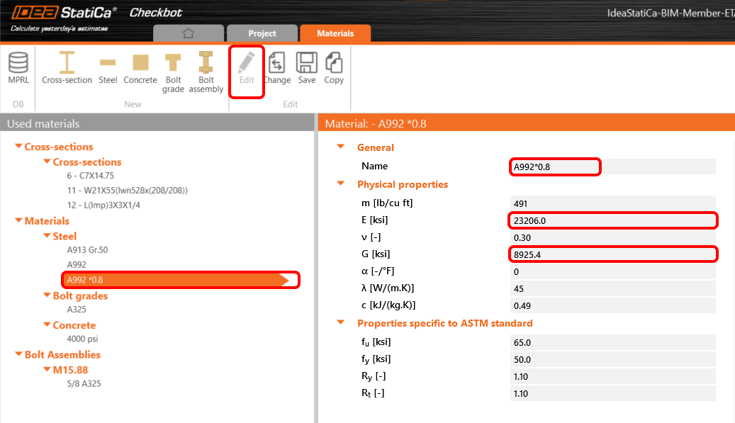
Before we open the module Member, we have to set the proper value of the modulus of elasticity in tension/compression and shear according to AISC 360-16.
First, add the new steel grade to the project's tab Material. Select steel A992.
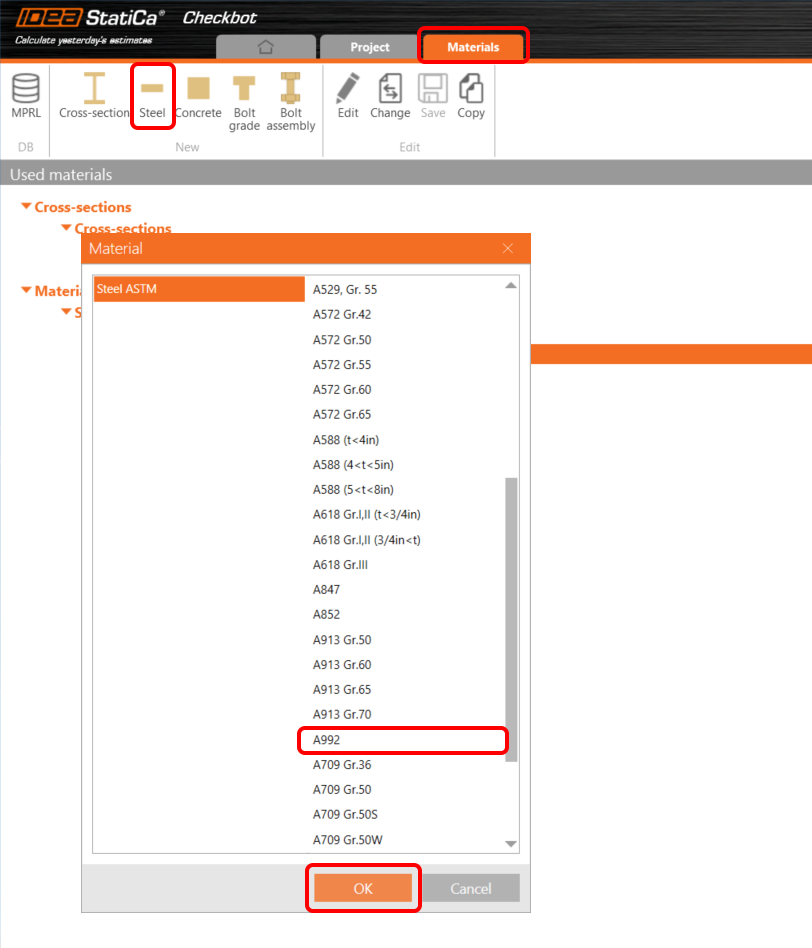
After that, by button Edit change the steel properties according to the following picture. The modulus of elasticity in tension/compression and shear is reduced by a factor of 0.8.
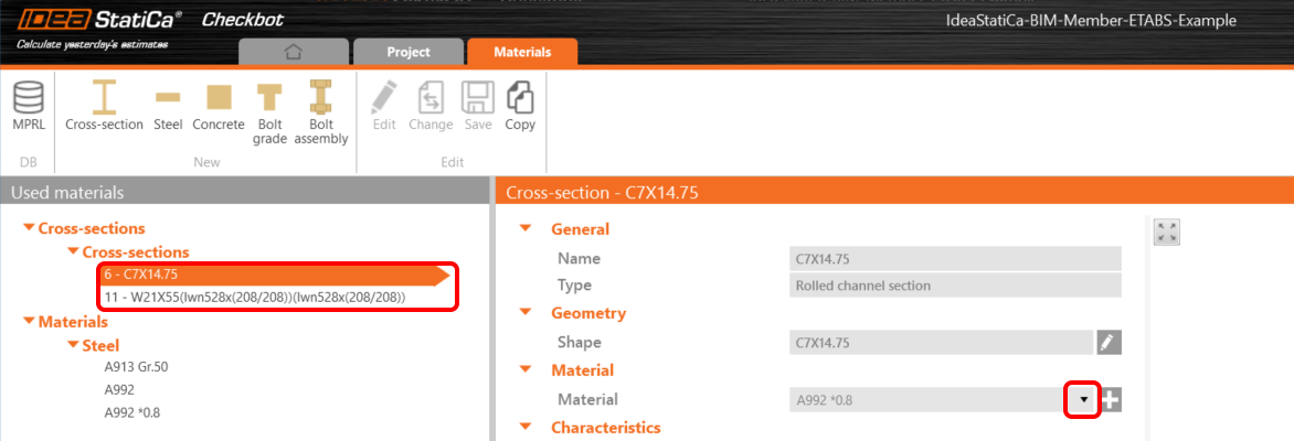
After that, select one cross-section after another, and set the correct value for the material as in the following picture.
Member modul
Now we can open the Member application. Just left-click on Open.
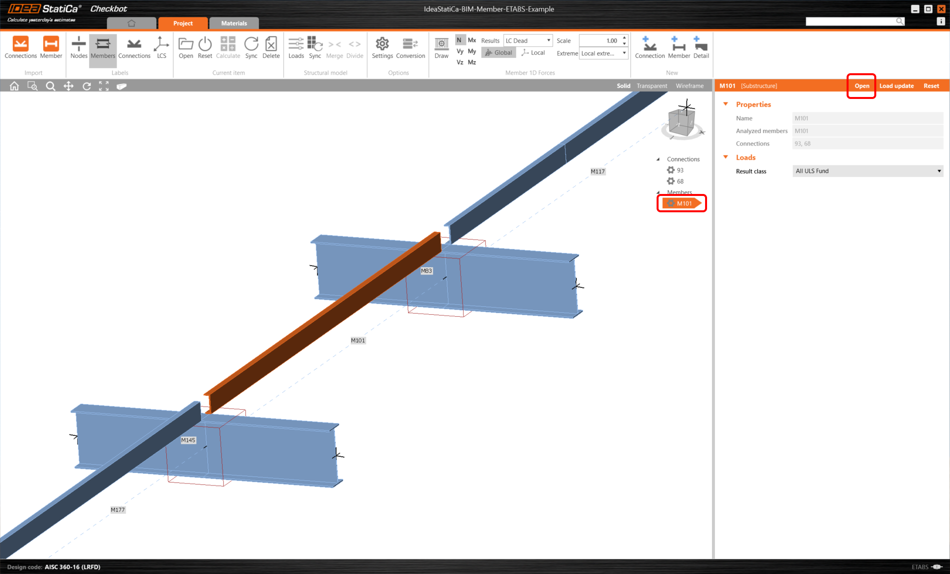
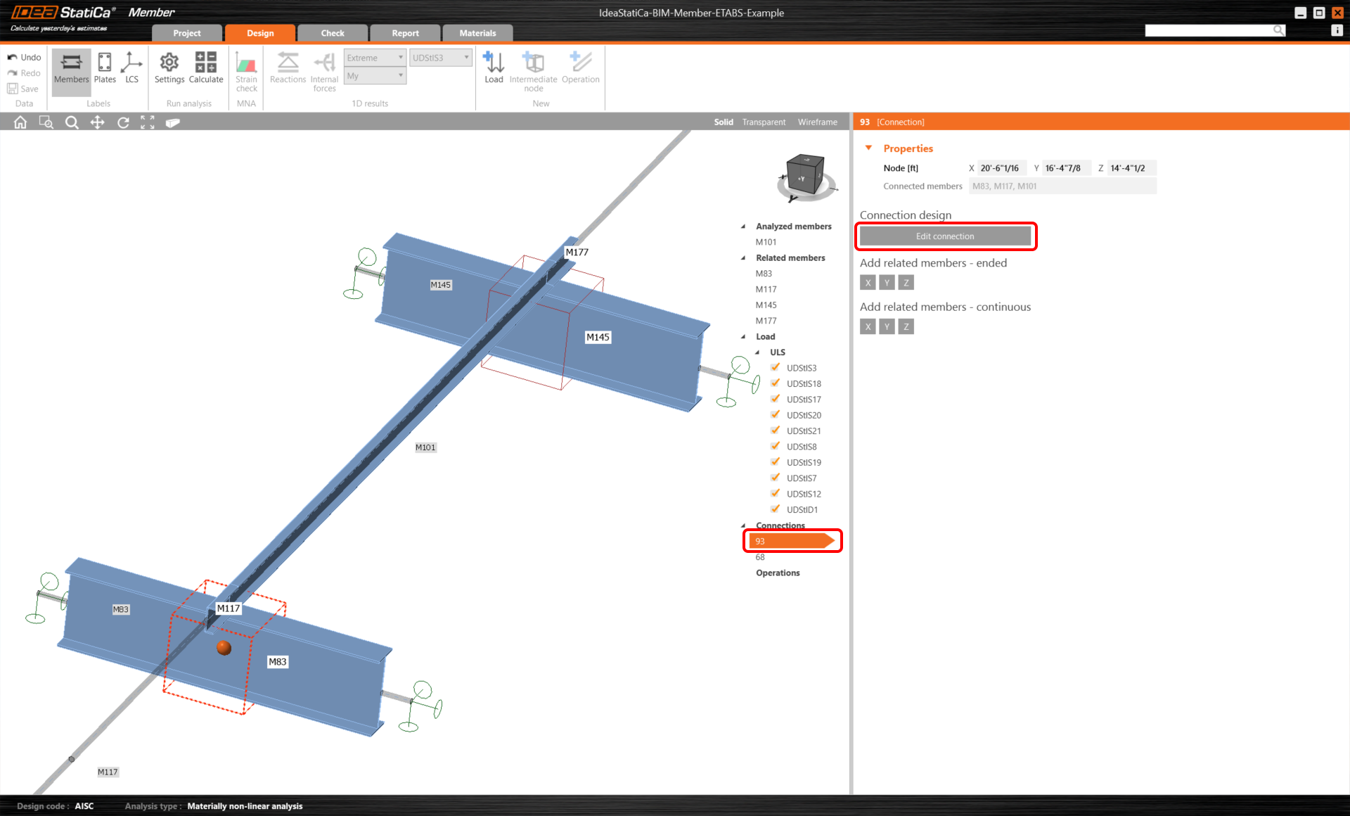
In the following picture, you can see the Member application immediately after launching.
In the beginning, let us design the joints of the member U-profile, so please select the first connection and click on Edit connection. As you can see now I-profile is represented by one element, thanks to the merging we made.
Connection Design
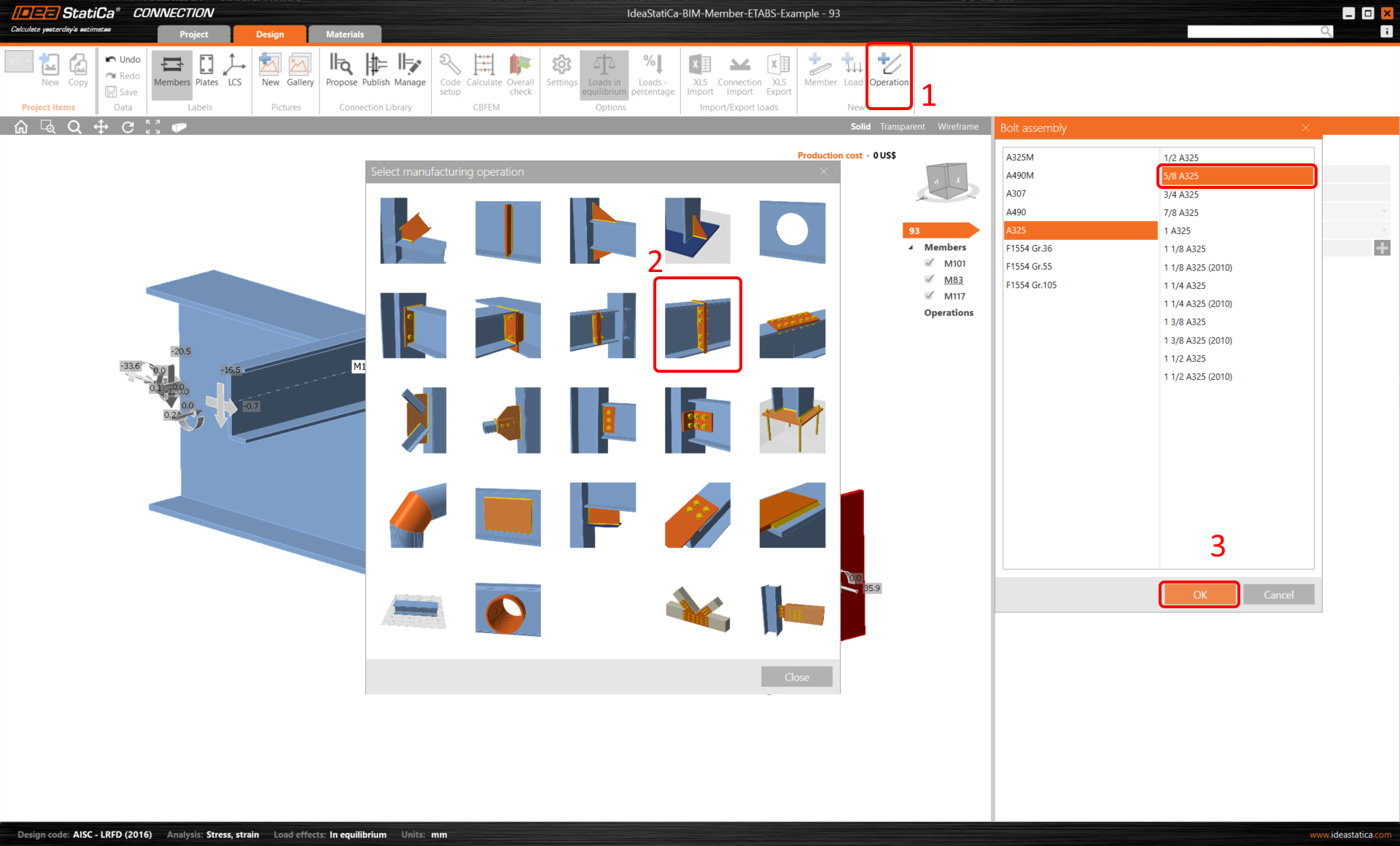
Click on Operation and select Plate to plate. Chose bolt A325 3/8 size.
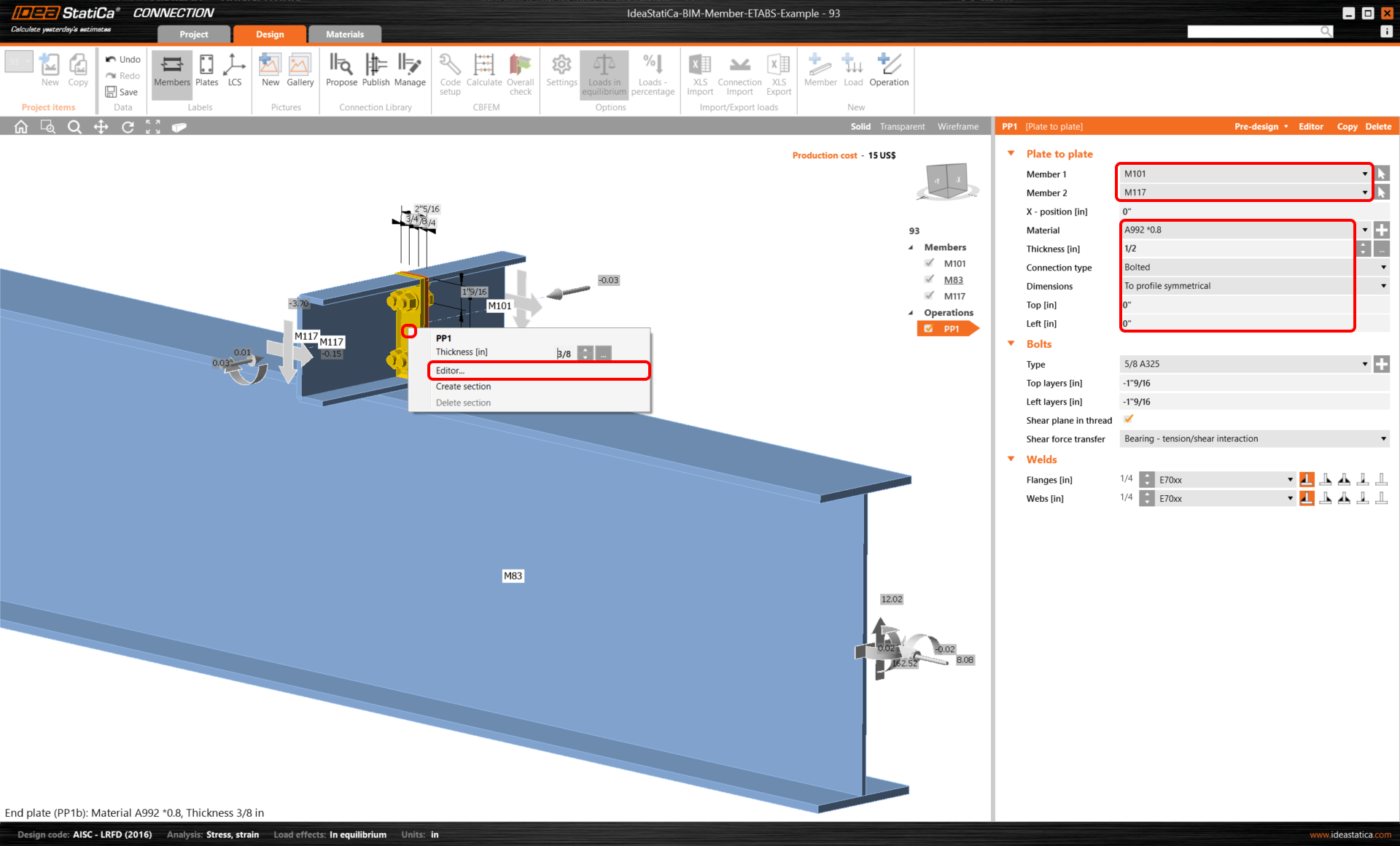
Change the values according to the following picture. Remember, according to AISC 360-16, use the material where the modulus of elasticity in tension/compression and shear is reduced by a factor of 0.8. After that, click on Editor.
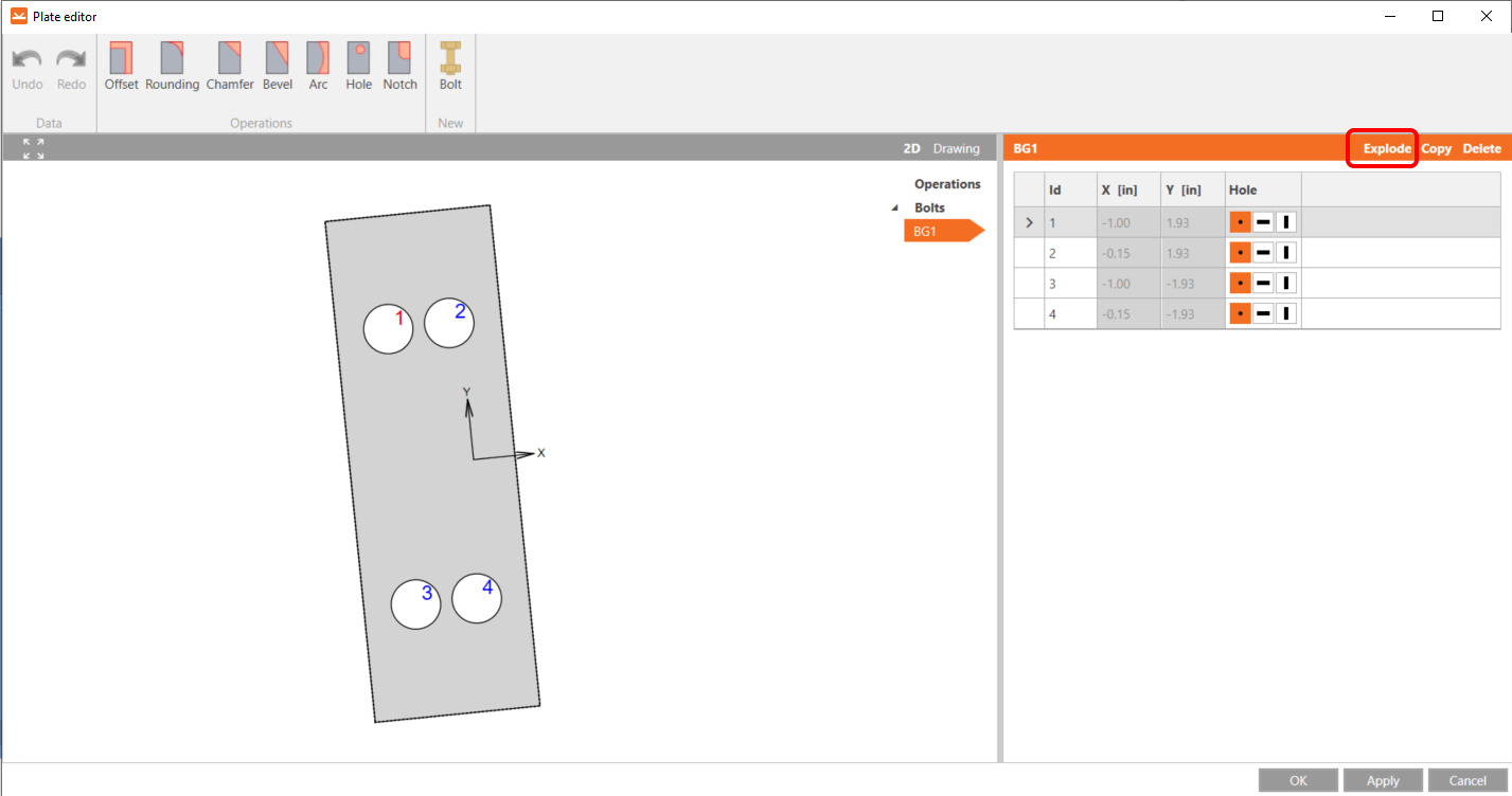
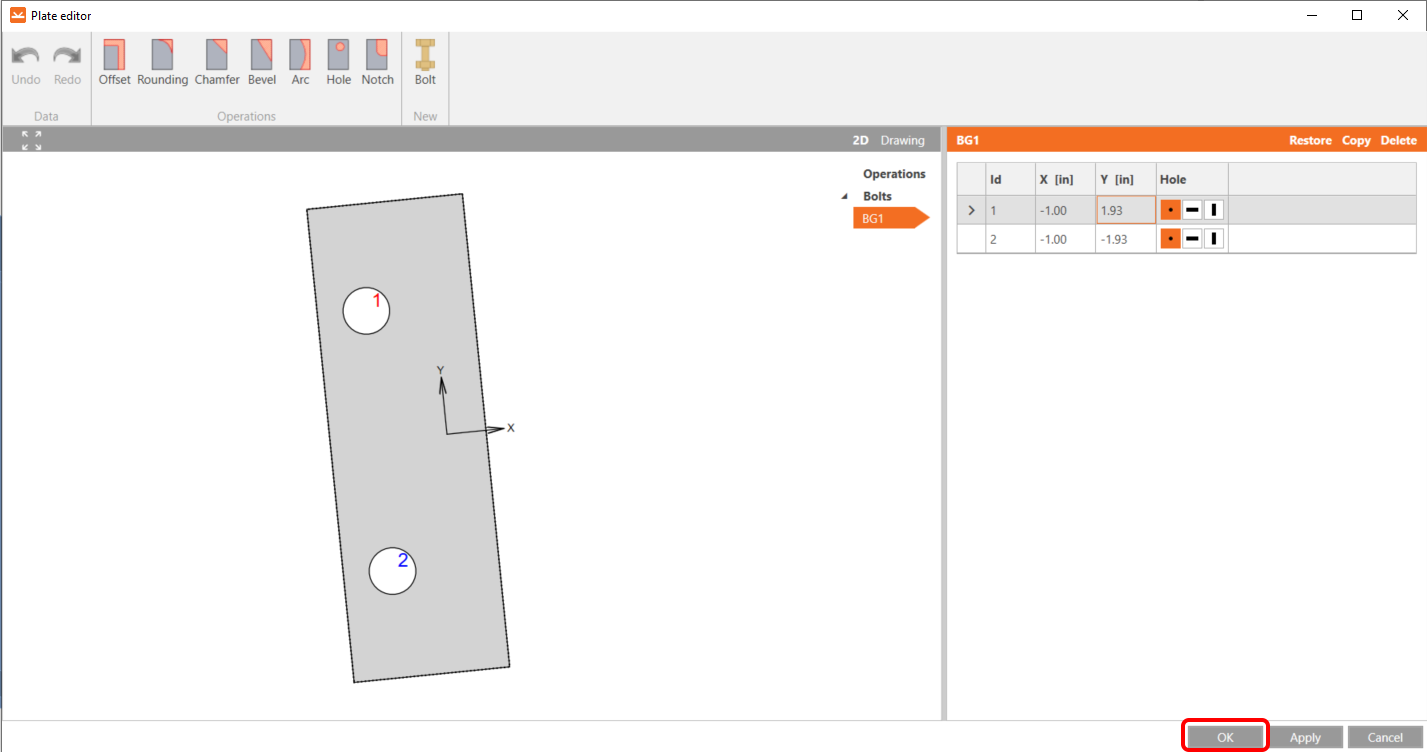
Click on Explode, delete the bolts Nr. 2 and 4, and click OK.
After you will make the changes, the element should look like this. Continue by clicking ok.
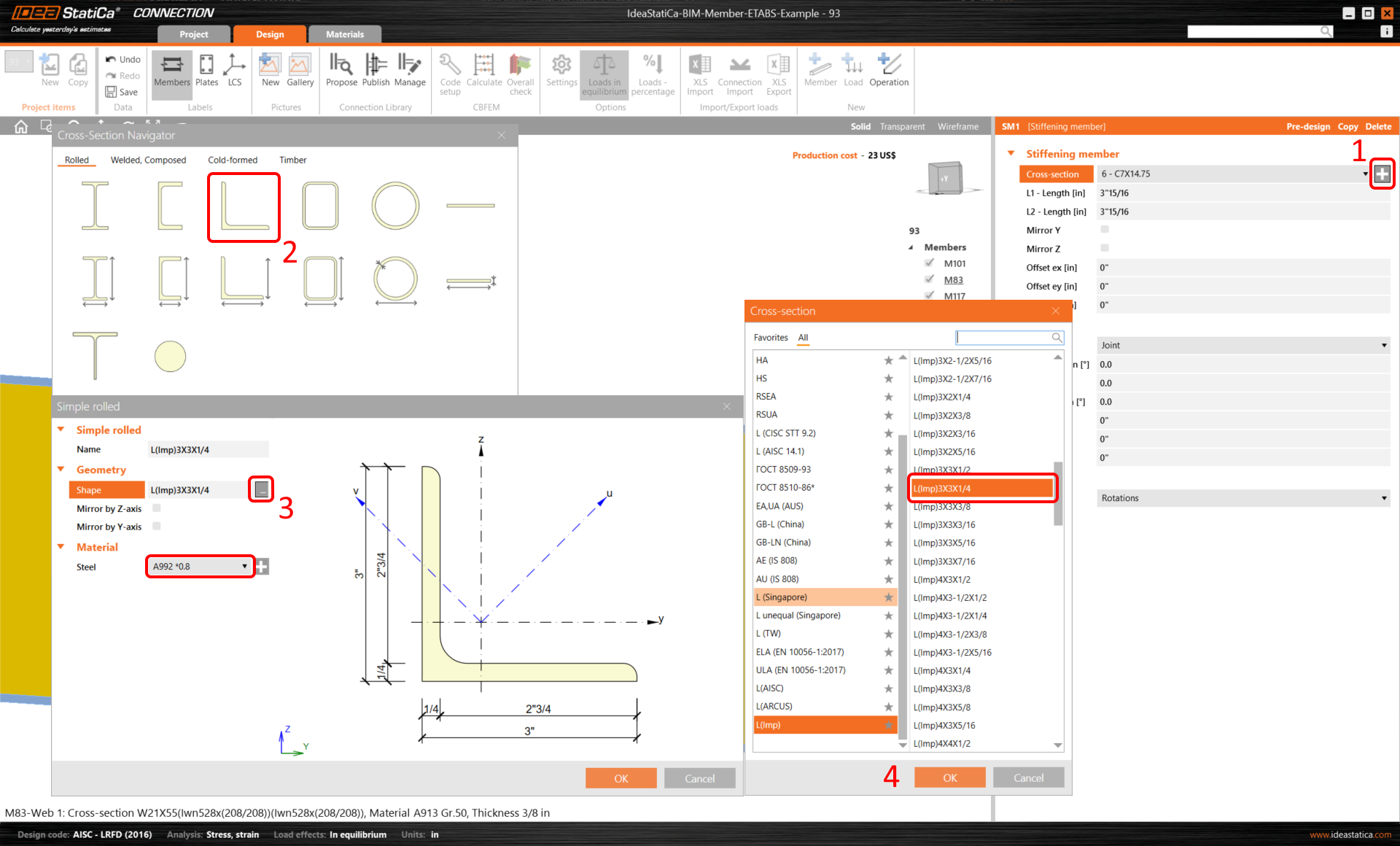
The next Operation is the Stiffening member, firstly add a new L-profile L(Imp)3x3x1/4 according to the following steps on the picture.
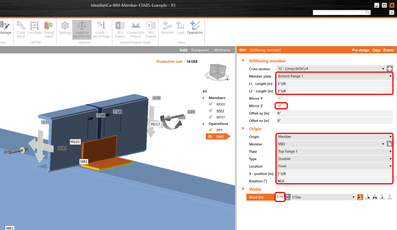
Then change the values according to the following instructions, the stiffening member should be positioned as shown.
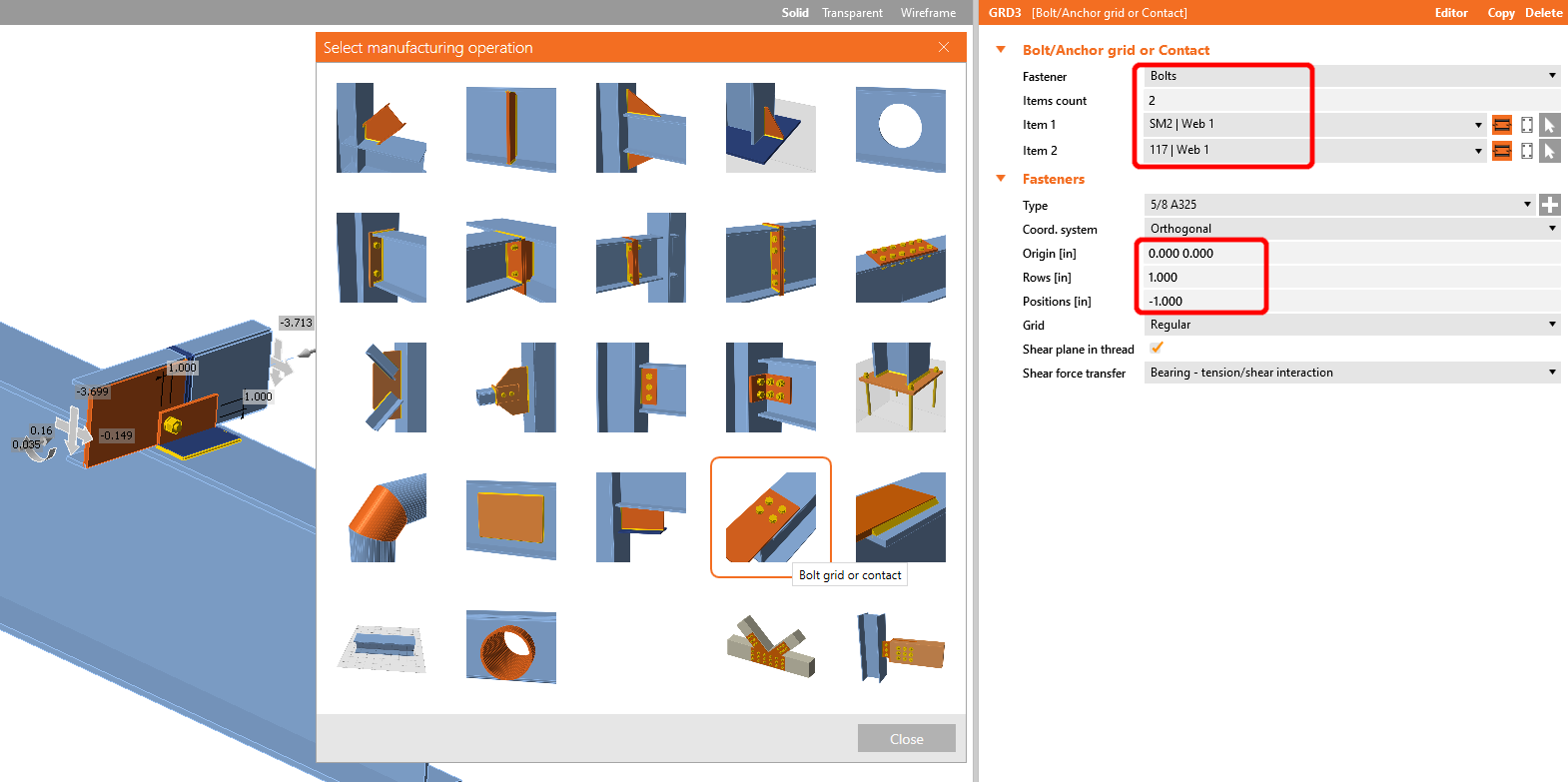
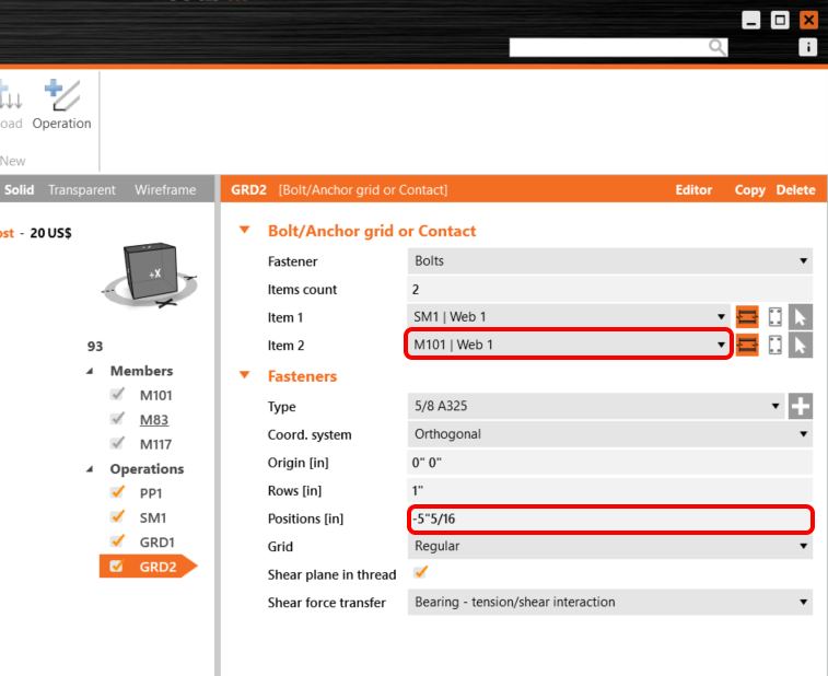
Add the operation Bolt/Anchor grid with the following values.
Copy the GRD1 operation and change the selected values, as shown in the picture.
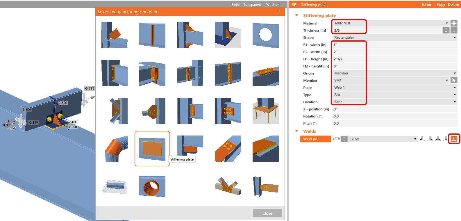
Now add a Stiffening plate to the joint with the following values.
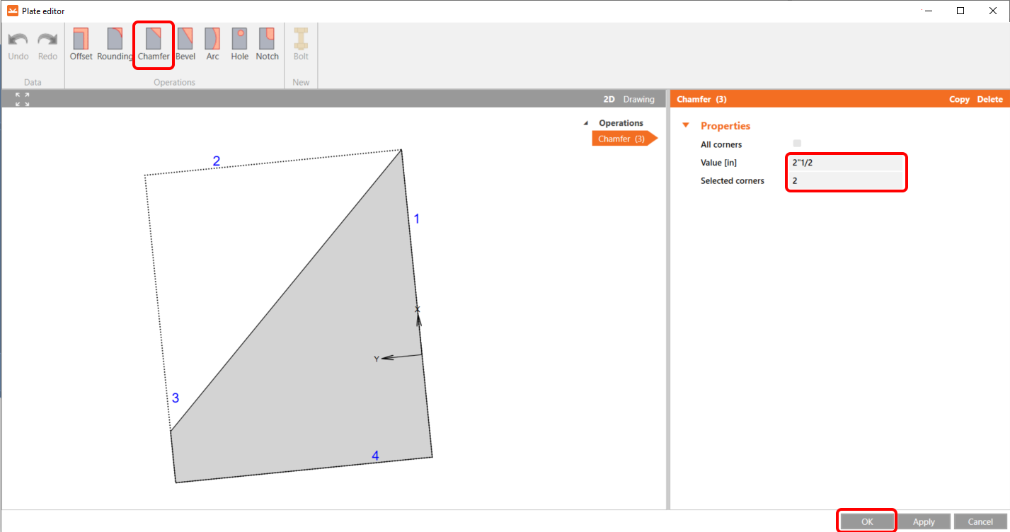
After that, In the Editor, make changes using the chamfer operation, and set it up according to the image.
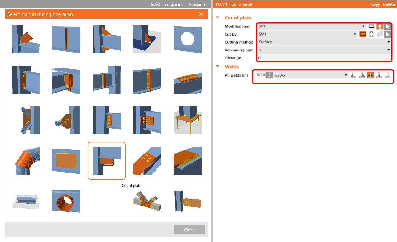
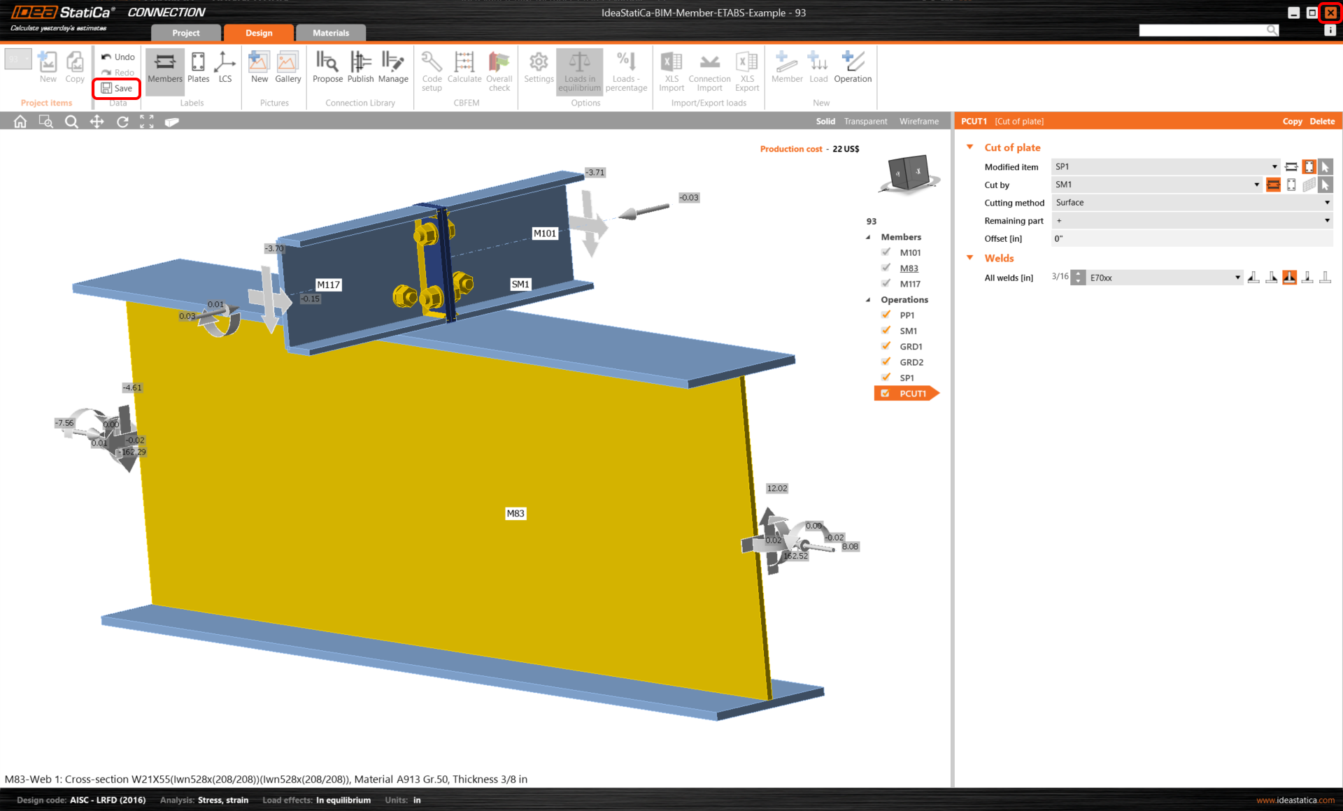
The last operation is the Cut of plate operation, using which we will connect our stiffening plate to the stiffening member by welds.
Now click on Save and close the module Connection.
Checking and Control
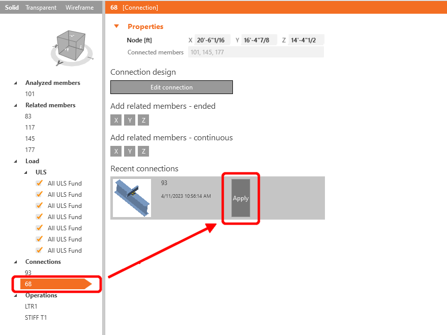
As we have similar joints on both sides of the member, you can copy the operations from the first joint to another. Select another joint, then click Apply.
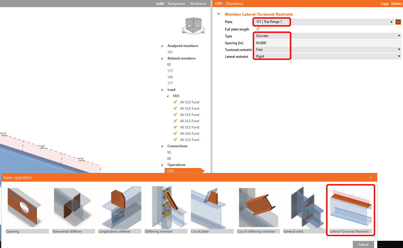
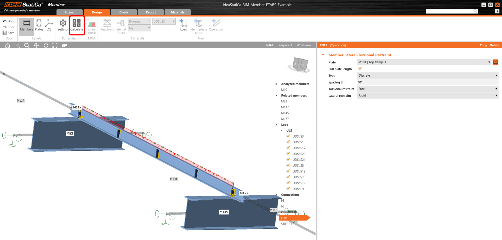
Before starting the analysis, firstly left-click on the U-member, add operation Lateral Restraint, and set up the values according to the picture.
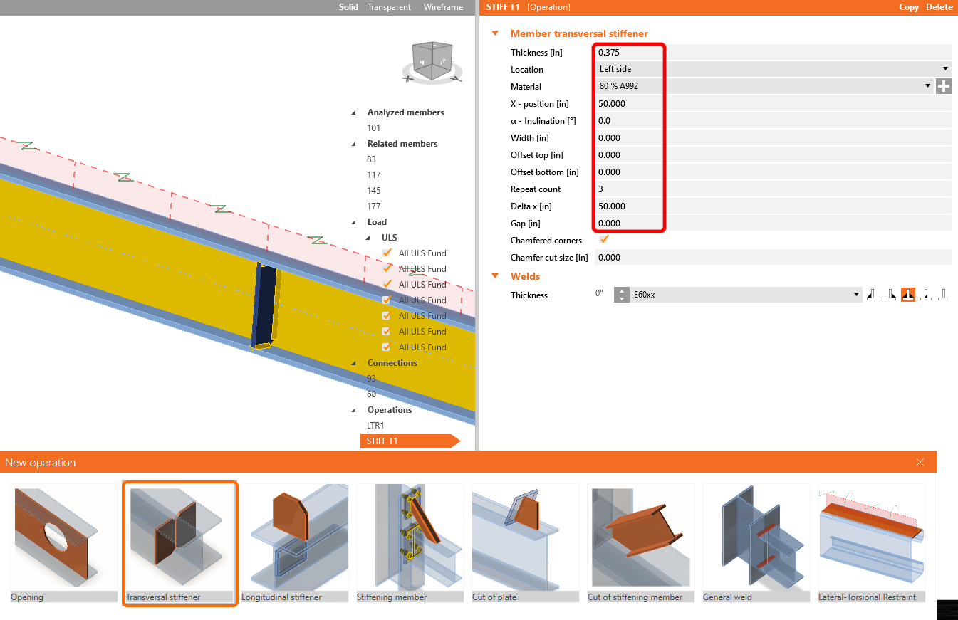
In the next step add operation Stiffeners the same way as in the previous step, and configure the values as shown.
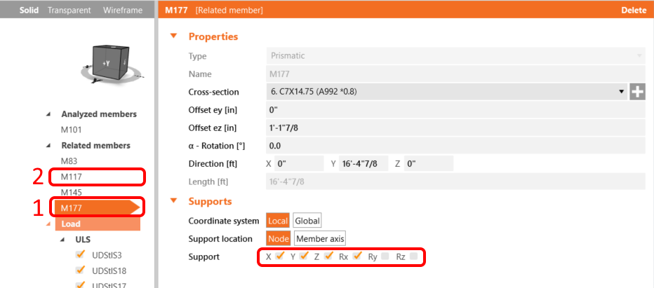
For the realistic behavior of the related members, restrict the supports of 177 and 117 to X, Y, Z, and Rx.
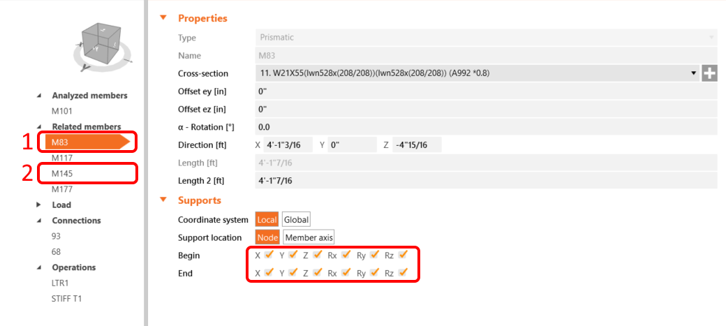
Also restrict the supports of 145 and 83 to X, Y, Z, and Rx, Ry, Rz.
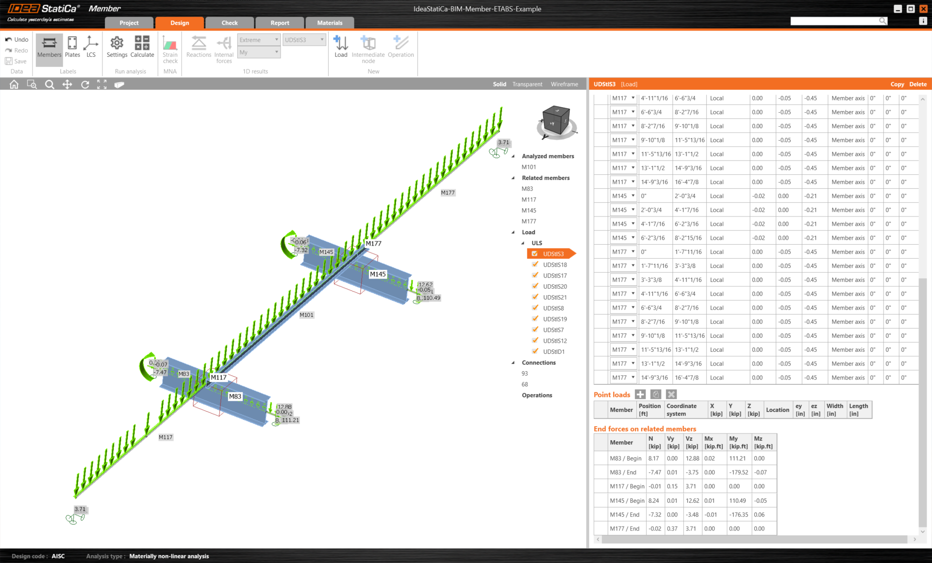
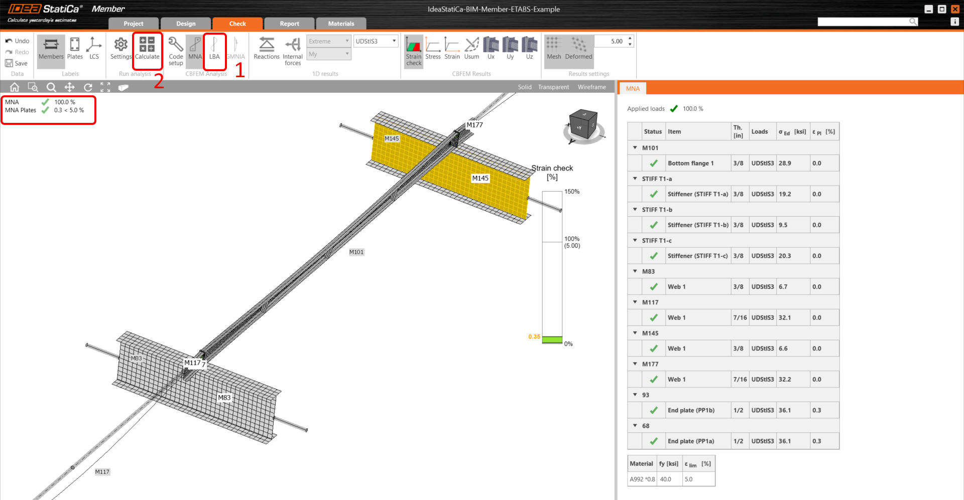
Now the member is ready to be analyzed. Click Calculate, it will run the MNA (materially non-linear) analysis.
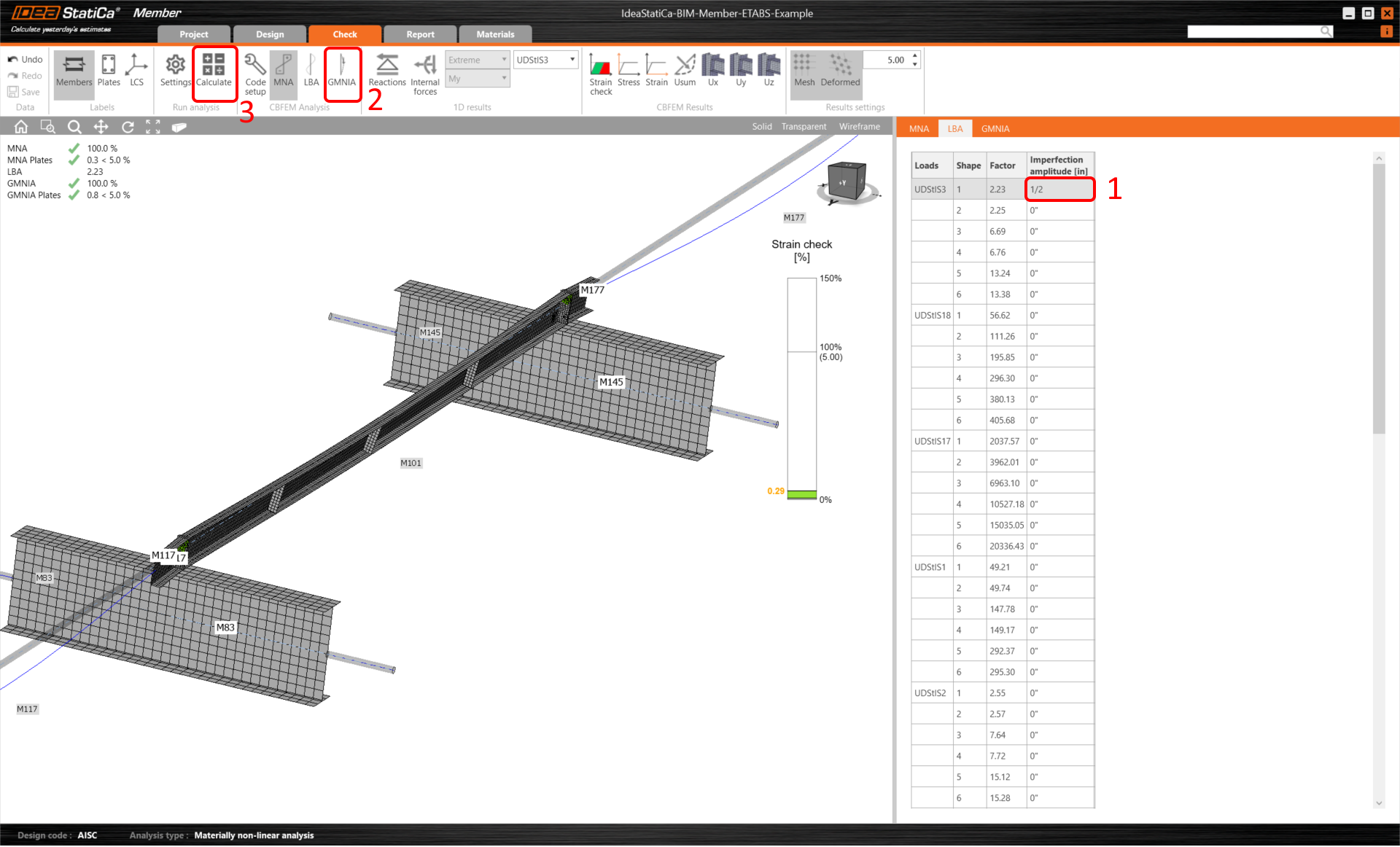
After that, you will see the result of the calculation, then select the tab Check and first click on the LBA button, consequently Calculate.
The second analysis is LBA (lateral buckling analysis), where we get a critical factor of less than 15.
This result shows the necessity of running the GMNIA (geometrically and materially non-linear analysis).
Because lateral-torsional buckling is investigated, factor k0 = 0.5 may be used. Amplitude 0.5 • 16,4 • 12 / 200 = 0,492 inches is applied to the first buckling mode.
Click on the imperfection field for the critical buckling factor, and fill the value we calculated above in the row, as shown in the following picture. Thenceforth you can run the last GMNIA (geometrically and materially non-linear) analysis.
Read more about member stability in IDEA StatiCa Member.
Here you can see the satisfied results, which means successful calculation.
You can check the total deformation of the member by clicking on Usum, as shown in the picture below.
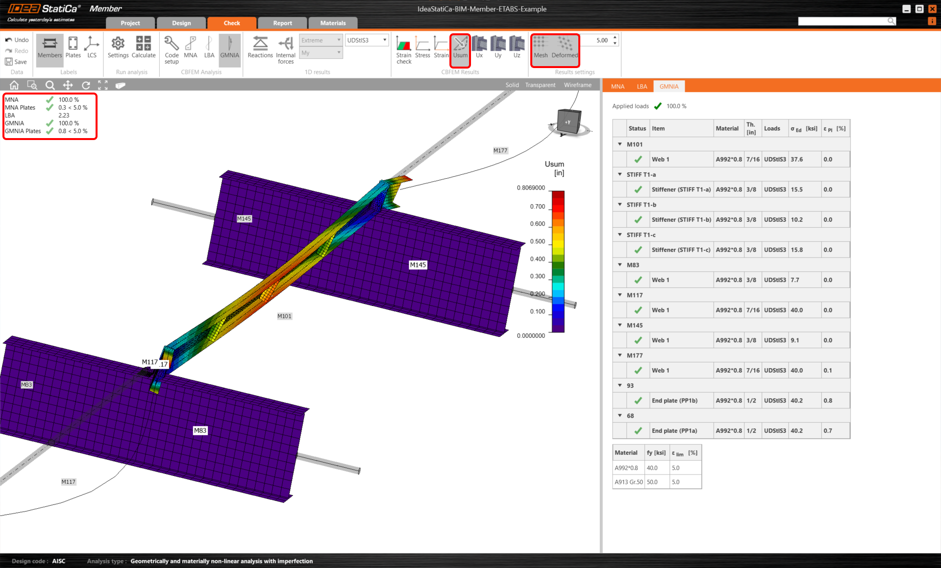
We have successfully imported and checked an element of the purlin from ETABS.
We have successfully imported and checked a purlin from ETABS.
Прикреплённые файлы
- ETABS_BIM_LINK_MEMBER_TUTORIAL.zip (ZIP, 292,6 MB)
- BIM-Member-ETABS-Example.EDB (EDB, 191 kB)