Descriere
Obiectul acestui studiu este verificarea metodei elementelor finite bazate pe componente (CBFEM) pentru o vută triunghiulară de clasa 4 fără talpă și o vută triunghiulară de clasa 4 cu talpă cu rigiditate redusă, cu modelul FEM de cercetare (RFEM) și modelul FEM de proiectare (DFEM).
Investigație experimentală
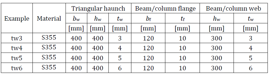
Sunt prezentate rezultatele experimentale ale șase epruvete de vute cu și fără tălpi. Trei epruvete sunt fără tălpi și trei epruvete sunt susținute de tălpi suplimentare. Epruvetele nerigidizate diferă prin grosimea inimii tw și lățimea inimii bw. Epruvetele rigidizate diferă prin grosimea inimii tw, grosimea tălpii tf și lățimea tălpii bf. Dimensiunile epruvetelor sunt rezumate în Tab. 6.1.1. Configurația de testare pentru epruveta fără talpă este prezentată în Fig. 6.1.1 (sus), iar pentru epruveta cu talpă în Fig. 6.1.1 (jos). Caracteristicile materialului plăcilor de oțel sunt rezumate în Tab. 6.1.2.
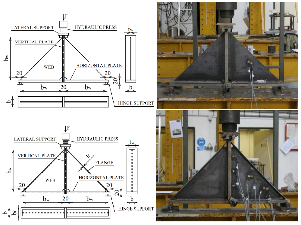
\[ \textsf{\textit{\footnotesize{Fig. 6.1.1 Geometria epruvetelor și configurația de testare}}}\]
Tab. 6.1.1 Prezentare generală a exemplelor
Tab. 6.1.2 Caracteristicile materialelor utilizate în modelele numerice

Modelul FEM de cercetare
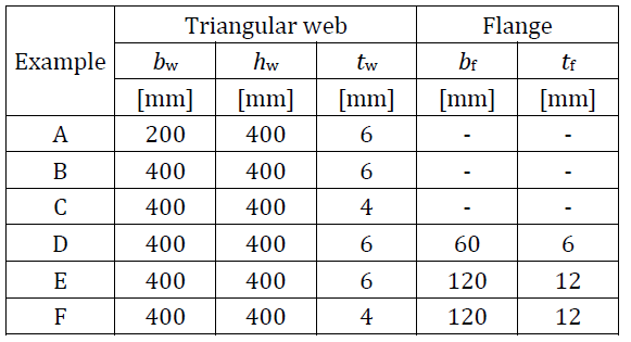
Modelul FEM de cercetare (RFEM) este utilizat pentru verificarea modelului DFEM și este validat pe baza experimentelor. În modelul numeric, se aplică elemente de coajă cvadrilaterale cu 4 noduri situate la colțuri, cu o lungime maximă a laturii de 10 mm. Se aplică analiza neliniară material și geometric cu imperfecțiuni (GMNIA). Imperfecțiunile geometrice echivalente sunt derivate din primul mod de flambaj, iar amplitudinea este stabilită conform Anexei C din EN 1993-1-5:2006. Modelele numerice sunt prezentate în Fig. 6.1.2.
\[ \textsf{\textit{\footnotesize{Fig. 6.1.2 Modelul FEM de cercetare a) vută fără talpă b) vută cu talpă}}\]
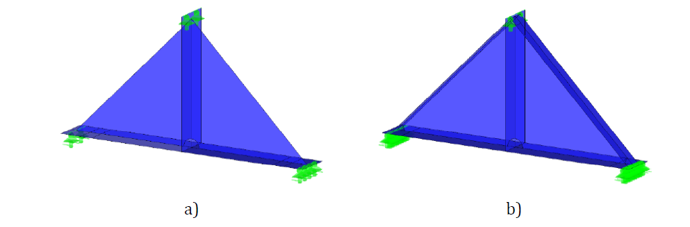
Un exemplu de comparație între RFEM și testul experimental privind comportamentul forță-deplasare este prezentat în Fig. 6.1.3a. Comparația rezistențelor măsurate în experiment și obținute din RFEM este prezentată în Fig. 6.1.3b. Rezistența calculată în modelul numeric este afișată pe axa orizontală. Rezistența măsurată în studiul experimental este afișată pe axa verticală. Se poate observa că există o bună concordanță.
\[ \textsf{\textit{\footnotesize{Fig. 6.1.3 a) Curba forță-deplasare a unei vute fără talpă b) Rezistențele experimentale comparate cu cele din RFEM}}}\]
Comparațiile stărilor finale de deformare între simulările numerice și rezultatele experimentale sunt efectuate la sfârșitul testelor. Fig. 6.1.4 prezintă comparația deformației epruvetelor A, B și D după cedare cu RFEA. Se poate constata că există o bună concordanță între modelele numerice și rezultatele experimentale ale vutelor în ceea ce privește modul de cedare. Pentru mai multe detalii, a se vedea (Kurejková și Wald, 2017).
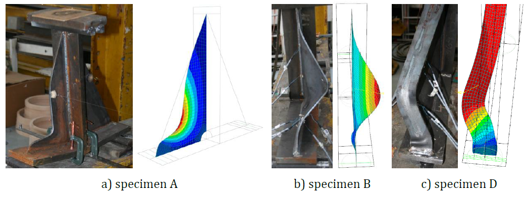
\[ \textsf{\textit{\footnotesize{Fig. 6.1.4 Deflecția experimentală și numerică a epruvetelor A, B și D după cedare}}}\]
Modelul FEM de proiectare
Procedura de proiectare pentru secțiunile transversale de clasa 4 este descrisă în secțiunea 3.10 Flambaj local.
Procedura de proiectare este verificată prin compararea modelelor DFEM și RFEM. Ambele modele sunt create în software-ul Dlubal RFEM. Procedura este aplicată în modelele CBFEM; a se vedea (Kurejková et al. 2015). Rezistența determinată de 5% deformație plastică este obținută în primul pas, urmată de analiza liniară de flambaj. Componenta critică în analiza de flambaj este studiată. Rezistența de calcul este interpolată până când condiția ρ∙αult,k = 1 este îndeplinită.
Primul mod de flambaj al unei vute fără talpă este prezentat în Fig. 6.1.5 a). Rezistența este evaluată conform formulei (3.10.2) din secțiunea 3.10. Comparația rezistențelor DFEM și RFEM este prezentată în Fig. 6.1.5 b). Rezistența calculată în DFEM este afișată pe axa orizontală. Rezistența calculată în RFEM este afișată pe axa verticală. Se poate observa că există o bună concordanță și că procedura este verificată.
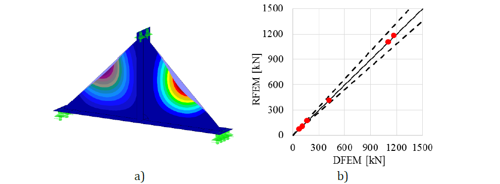
\[\textsf{\textit{\footnotesize{Fig. 6.1.5 a) Primul mod de flambaj al modelului DFEM b) Comparația rezistențelor DFEM și RFEM}}}\]
Comportament global și verificare
Este pregătită o comparație a comportamentului global al unei vute fără talpă descris prin diagrame forță-deplasare în modelul DFEM. Deplasarea este măsurată în direcție verticală în mijlocul epruvetei. Atenția este concentrată pe caracteristicile principale: rezistența de calcul și sarcina critică. Două exemple de vute fără talpă sunt alese ca referință; a se vedea Fig. 6.1.6. Procedura de proiectare în modelele DFEM acoperă rezerva post-flambaj, care este observată în Fig. 6.1.6 a). Sarcina critică Fcr este mai mică decât rezistența de calcul FDFEM. Rezerva post-flambaj este observată în cazurile cu plăci foarte zvelte. Diagrama tipică este prezentată în Fig. 6.1.6 b), unde rezistența de calcul FDFEM nu atinge sarcina critică Fcr. Sarcina Fult,k se referă la rezistența corespunzătoare unui procent de 5% deformație plastică.
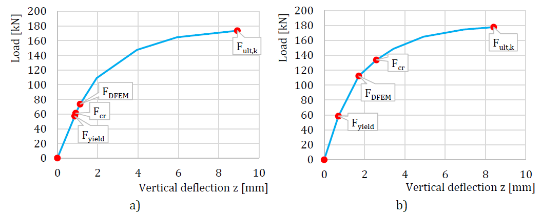
\[ \textsf{\textit{\footnotesize{Fig. 6.1.6 a) Curba forță-deplasare cu rezervă post-flambaj b) Curba forță-deplasare fără rezervă post-flambaj (Kuříková et al. 2019)}}}\]
Procedura de proiectare în modelele CBFEM este descrisă în secțiunea 3.10 Flambaj local. Analiza de flambaj este implementată în software. Calculul rezistențelor de calcul se efectuează manual conform procedurii de proiectare. FCBFEM este interpolat de utilizator până când formula (2) este egală cu 1. Este studiat un nod grindă-stâlp cu o vută fără talpă. Grosimile inimilor grinzii și stâlpului variază în același mod ca și grosimea vutei triunghiulare. Aceeași secțiune transversală este utilizată pentru grindă și stâlp. Geometria exemplelor este descrisă în Tab. 6.1.3. Nodul este încărcat cu moment încovoietor.
Tab. 6.1.3 Prezentare generală a exemplelor (Kuříková et al. 2019)
Verificarea rezistenței
Rezistența de calcul calculată prin CBFEM este comparată cu rezultatele obținute prin RFEM. Comparația este axată pe rezistența de calcul și sarcina critică. Rezultatele sunt prezentate în Tab. 6.1.4. Diagrama din Fig. 6.1.7 c) prezintă influența grosimii elementului de lărgire asupra rezistențelor și sarcinilor critice în exemplele examinate.
Rezultatele arată o concordanță foarte bună în ceea ce privește sarcina critică și rezistența de calcul. Rezerva post-flambaj este observată pentru inima grinzii și elementul de lărgire triunghiular cu grosimi de 3 și 4 mm. Modelul CBFEM al nodului cu o vută cu grosimea de 3 mm este prezentat în Fig. 6.1.7 a). Primul mod de flambaj al nodului este prezentat în Fig. 6.1.7 b).
Tab. 6.1.4 Rezistența de calcul

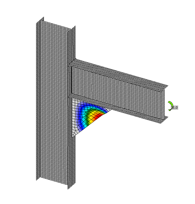
\[ \textsf{\textit{\footnotesize{a)}}}\]

\[ \textsf{\textit{\footnotesize{b)}}}\]
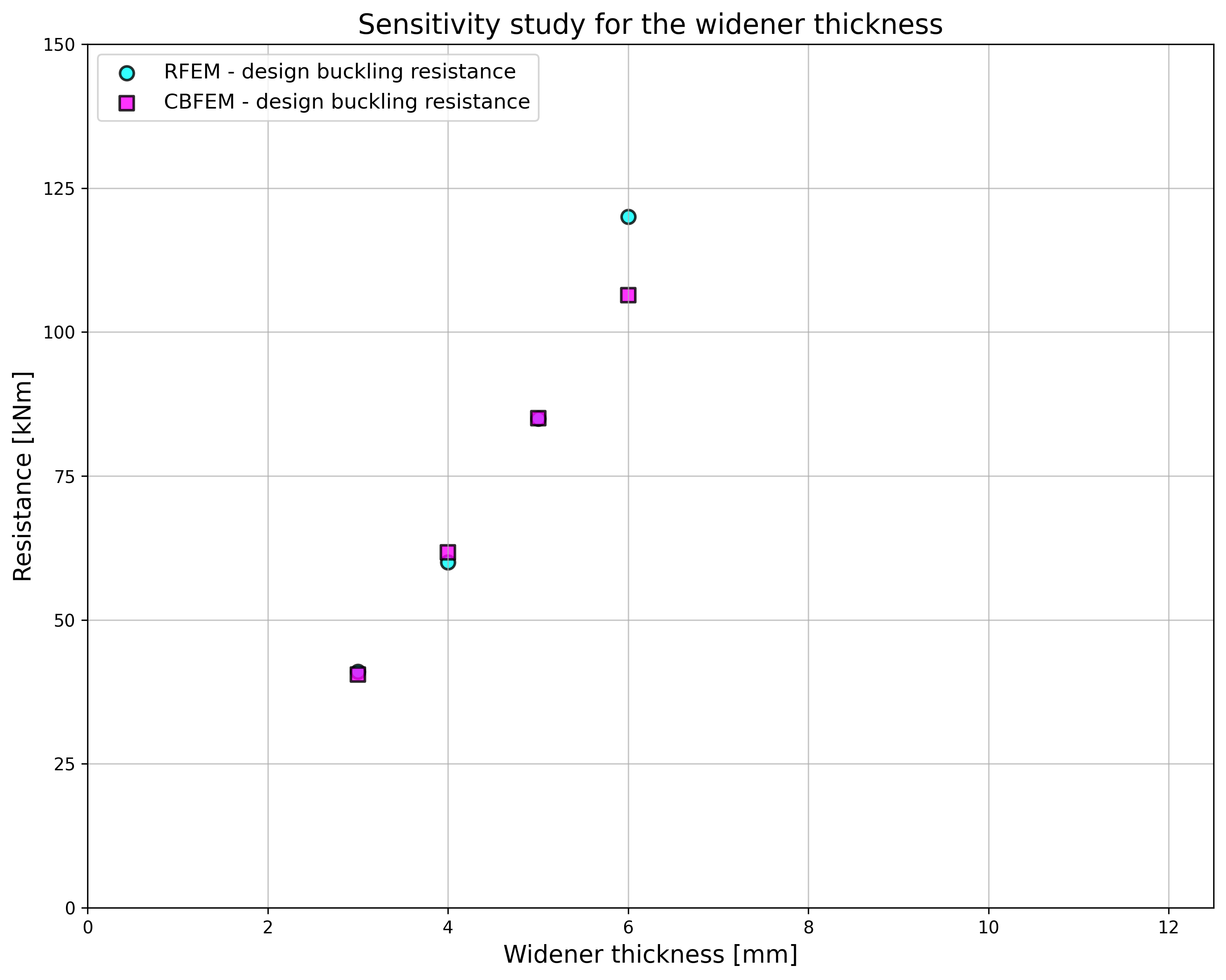
\[ \textsf{\textit{\footnotesize{c)}}}\]
\[ \textsf{\textit{\footnotesize{Fig. 6.1.7 a) Primul mod de flambaj b) Modelul CBFEM c) Influența grosimii elementului de lărgire asupra rezistențelor și sarcinilor critice}}}\]
Studiile de verificare confirmă acuratețea modelului CBFEM pentru predicția comportamentului unei vute triunghiulare. Rezultatele CBFEM sunt comparate cu rezultatele RFEM. Procedura de proiectare este verificată pe modelul RFEM, care este validat pe experimente. Toate procedurile prezic un comportament global similar al nodului.
Exemplu de referință
Date de intrare
Grindă și stâlp
• Oțel S355
• Grosimea tălpii tf = 10 mm
• Lățimea tălpii bf = 120 mm
• Grosimea inimii tw = 3 mm
• Înălțimea inimii hw = 300 mm
Vută triunghiulară
• Grosimea tw = 3 mm
• Lățimea bw = 400 mm
• Înălțimea hw = 400 mm
Calculați
• Analiza de flambaj
Date de ieșire
• Rezistența plastică CBFEM = 138 kNm
• Rezistența de calcul la flambaj CBFEM = 41 kNm
• Factorul critic de flambaj (pentru Rezistența de calcul la flambaj CBFEM = 41 kNm) αcr = 0,52
• Factorul de încărcare la 5% deformație plastică αult,k = Rezistența plastică CBFEM / Rezistența de calcul la flambaj CBFEM = 138 / 41 = 3,40
\[ \textsf{\textit{\footnotesize{Fig. 6.1.7 Vută triunghiulară calculată în exemplul de referință}}}\]