Check of steel connection components (IS 800)
Normtoetsing van platen volgens Indiase norm
De resulterende equivalente spanning (HMH, von Mises) en plastische rek worden berekend op platen. Wanneer de rekenwaarde van de vloeigrens, \( f_y / \gamma_{m0} \) (IS:800, Cl. 5.4.1), op het bilineaire materiaaldiagram wordt bereikt, wordt de controle van de equivalente plastische rek uitgevoerd. De grenswaarde van 5% wordt aanbevolen in de Eurocode (EN 1993-1-5 App. C, Par. C8, Noot 1). Deze waarde kan worden aangepast in de Code-instellingen, maar verificatiestudies zijn uitgevoerd voor deze aanbevolen waarde.
Het plaatelement is verdeeld in 5 lagen, en elastisch/plastisch gedrag wordt in elk van deze lagen onderzocht. Het programma toont het maatgevende resultaat van alle lagen.
De spanning kan iets hoger zijn dan de rekenwaarde van de vloeigrens. De reden hiervoor is de lichte helling van de plastische tak van het spanning-rek diagram, die in de berekening wordt gebruikt om de stabiliteit van de berekening te verbeteren.
Normtoetsing van lassen volgens Indiase normen
Stompe lassen
De verificatie van volledig doorgelaste stompe lassen wordt niet uitgevoerd, omdat wordt aangenomen dat deze dezelfde weerstand hebben als het profiel, zolang het basismateriaal voor de stompe las superieur is aan dat van het profiel (IS 800:2007, 10.5.7.1.2).
Hoeklassen
Hoeklassen worden gecontroleerd volgens IS 800, Cl. 10.5.10.1.1:
\[ f_e = \sqrt{f_a^2 + 3q^2} \le f_{wd} = \frac{f_u}{\sqrt{3} \gamma_{mw}} \]
waarbij:
- \( f_e \) – equivalente spanning in de las
- \( f_a \) – normaalspanningen, druk of trek, ten gevolge van normaalkracht of buigmoment
- \( q \) – afschuifspanning ten gevolge van dwarskracht of trek
- \( f_{wd} \) – rekenwaarde sterkte van een hoeklas
- \( f_u \) – kleinste waarde van de breukspanning van de las of van het basismateriaal; de treksterkte van de laselectrode wordt verondersteld beter te zijn dan die van het basismateriaal
- \( \gamma_{mw} \) – partiële veiligheidsfactor voor lassen – IS 800, Tabel 5; aanpasbaar in de norminstellingen
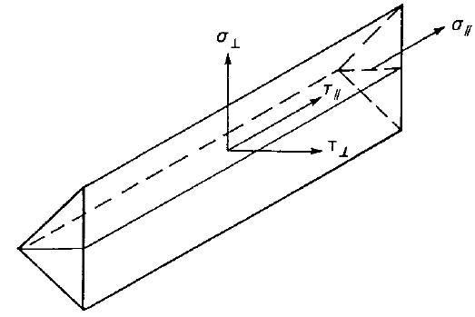
De lasdiagrammen tonen de spanning volgens de volgende formule:
\[ \sigma = \sqrt{\sigma_{\perp}^2 + \tau_{\perp}^2 + 3 \tau_{\parallel}^2 } \]
Normtoetsing van bouten volgens Indiase norm
Afschuifcapaciteit van bouten
De rekensterkte van de bout, \(V_{dsb}\), bepaald door de afschuifsterkte, is gegeven door IS 800, Cl. 10.3.3:
\[ V_{sb} \le V_{dsb} \]
waarbij:
- \(V_{dsb} = V_{nsb}/\gamma_{mb}\) – rekenmatige afschuifcapaciteit van een bout
- \(V_{nsb} = \frac{f_{ub}}{\sqrt{3}} A_e\) – nominale afschuifcapaciteit van een bout
- \(f_{ub}\) – ultieme treksterkte van een bout;
- \(A_e\) – oppervlak voor het weerstaan van afschuiving; \(A_e = A_n\) voor het afschuifvlak dat door de schroefdraad wordt gesneden, \(A_e = A_s\) voor het geval waarbij de schroefdraad niet in het afschuifvlak valt
- \(A_n\) – netto trekspanningsoppervlak van de bout
- \(A_s\) – dwarsdoorsnede-oppervlak ter plaatse van de schacht
- \(\gamma_{mb} = 1.25\) – partiële veiligheidsfactor voor bouten – druktype – IS 800, Tabel 5; aanpasbaar in Code setup
Wanneer de griplengte van bouten \(l_g\) (gelijk aan de totale dikte van de verbonden platen) groter is dan \(5d\), wordt de rekenmatige afschuifcapaciteit \(V_{dsb}\) verminderd met een factor \(\beta_{lg}\) – IS 800, Cl. 10.3.3.2:
\[ \beta_{lg} = \frac{8}{3+l_g/d} \]
Volgens IS 800, Cl. 10.3.3.3 dient de rekenmatige afschuifcapaciteit van bouten die afschuiving overdragen via een opvulplaat met dikte \(t_{pk} \ge 6\) mm te worden verminderd met een factor:
\[ \beta_{pk} = (1-0.0125 t_{pk}) \]
Elk afschuifvlak wordt afzonderlijk gecontroleerd en het maatgevende resultaat wordt getoond.
Drukkapaciteit van bouten
De rekenmatige druksterkte van een bout op een willekeurige plaat, bepaald door druk, is gegeven door IS 800, Cl. 10.3.4:
\[ V_{sb} \le V_{dpb} \]
waarbij:
- \(V_{dpb} = V_{npb} / \gamma_{mb}\) – rekenmatige druksterkte van een bout
- \(V_{npb} = 2.5 k_b d t f_u\) – nominale druksterkte van een bout
- \(k_b = \min \left \{ \frac{e}{3d_0}, \, \frac{p}{3d_0}-0.25, \, \frac{f_{ub}}{f_u}, \, 1.0 \right \}\) – factor voor verbindingsgeometrie en materiaalsterkte
- \(e\) – randafstand van het bevestigingsmiddel in de drukrichting
- \(p\) – hartafstand van het bevestigingsmiddel in de drukrichting
- \(f_{ub}\) – ultieme treksterkte van de bout
- \(f_u\) – ultieme treksterkte van de plaat
- \(d\) – nominale diameter van de bout
- \(d_0\) – diameter van het boutgat
- \(t\) – plaatdikte
- \(\gamma_{mb} = 1.25\) – partiële veiligheidsfactor voor bouten – druktype – IS 800, Tabel 5; aanpasbaar in Code setup
De druk op elke plaat wordt afzonderlijk gecontroleerd en het maatgevende resultaat wordt getoond.
De drukweerstand wordt verminderd voor oversized en sleuvengatboringen met een factor:
- 0,7 – voor oversized en korte sleuvengatboringen
- 0,5 – voor lange sleuvengatboringen
De afmetingen van oversized, korte sleuvengaten en lange sleuvengaten worden bepaald volgens IS 800, Tabel 19.
Trekcapaciteit van bouten
Een bout onderworpen aan een maatgevende trekkracht wordt gecontroleerd volgens IS 800, Cl. 10.3.5:
\[ T_b \le T_{db} \]
waarbij:
- \(T_{db} = T_{nb} / \gamma_{mb}\) – rekenmatige trekcapaciteit van de bout
- \(T_{nb} = \min \{ 0.9 f_{ub} A_n, \, f_{yb} A_s (\gamma_{mb} / \gamma_{m0}) \}\) – nominale trekcapaciteit van de bout
- \(f_{ub}\) – ultieme treksterkte van de bout
- \(f_{yb}\) – vloeigrens van de bout
- \(A_n\) – netto trekspanningsoppervlak van de bout
- \(A_s\) – dwarsdoorsnede-oppervlak ter plaatse van de schacht
- \(\gamma_{mb} = 1.25\) – partiële veiligheidsfactor voor bouten – druktype – IS 800, Tabel 5; aanpasbaar in Code setup
- \(\gamma_{m0} = 1.1\) – partiële veiligheidsfactor voor weerstand bepaald door vloeien – IS 800, Tabel 5; aanpasbaar in Code setup
Bout onderworpen aan gecombineerde afschuiving en trek
Een bout die zowel een rekenmatige afschuifkracht als een rekenmatige trekkracht tegelijkertijd moet weerstaan, dient volgens IS 800, Cl. 10.3.6 te voldoen aan:
\[ \left( \frac{V_{sb}}{V_{db}} \right)^2 + \left( \frac{T_{b}}{T_{db}} \right)^2 \le 1.0 \]
waarbij:
- \(V_{sb}\) – maatgevende afschuifkracht
- \(V_{db} = \min \{ V_{dsb}, \, V_{dpb} \}\) – rekenmatige afschuifweerstand van de bout – IS 800, Cl. 10.3.2
- \(V_{dsb}\) – rekenmatige afschuifweerstand
- \(V_{dpb}\) – rekenmatige drukweerstand
- \(T_b\) – maatgevende trekkracht
- \(T_{db}\) – rekenmatige trekcapaciteit van de bout
Normtoetsing van voorbelaste bouten volgens Indiase normen
Glijweerstand
De glijweerstand van een voorbelaste bout wordt gecontroleerd volgens IS 800, Cl. 10.4.3:
\[ V_{sf} \le V_{dsf} \]
waarbij:
- \(V_{dsf} = V_{nsf} / \gamma_{mf}\) – rekenwaarde van de afschuifcapaciteit van een bout bepaald door glijden voor een wrijvingsverbinding
- \(V_{nsf} = \mu_f n_e K_h F_0\) – nominale afschuifcapaciteit van een bout bepaald door glijden voor een wrijvingsverbinding
- \(\mu_f\) – wrijvingscoëfficiënt (glijfactor) zoals gespecificeerd in IS 800, Tabel 20; aanpasbaar in de norminstelling
- \(n_e = 1\) – aantal effectieve contactvlakken dat wrijvingsweerstand tegen glijden biedt; elk afschuifvlak wordt afzonderlijk gecontroleerd
- \(K_h\) – factor voor boutgaten; \(K_h = 1.0\) voor bevestigingsmiddelen in standaard gaten, \(K_h = 0.85\) voor bevestigingsmiddelen in oversized en kort gesleufde gaten, \(K_h = 0.7\) voor bevestigingsmiddelen in lang gesleufde gaten
- \(\gamma_{mf}\) – partiële veiligheidsfactor voor bouten – wrijvingstype – IS 800, Tabel 5, \(\gamma_{mf}=1.10\) als de glijweerstand is ontworpen bij gebruiksbelasting, \(\gamma_{mf}= 1.25\) als de glijweerstand is ontworpen bij uiterste belasting; aanpasbaar in de norminstelling
- \(F_0 = A_n f_0\) – minimale boutspanning (proefbelasting) bij installatie
- \(A_n\) – netto trekspanningsoppervlak van de bout
- \(f_0 = 0.7 f_{ub}\) – proefspanning
De capaciteit na glijden (IS 800, Cl. 10.4.4) dient te worden gecontroleerd door het bouttype te wijzigen van wrijving naar drukcontact – trek/afschuiving interactie voor de rekencapaciteit bij uiterste belasting.
Trekcapaciteit van bouten
Een bout onderworpen aan een berekende trekkracht wordt gecontroleerd volgens IS 800, Cl. 10.3.5:
\[ T_f \le T_{df} \]
waarbij:
- \(T_{df} = T_{nf} / \gamma_{mf}\) – rekenwaarde van de trekcapaciteit van de wrijvingsbout
- \(T_{nf} = \min \{ 0.9 f_{ub} A_n, \, f_{yb} A_s (\gamma_{mf} / \gamma_{m0}) \}\) – nominale trekcapaciteit van de wrijvingsbout
- \(f_{ub}\) – ultieme treksterkte van de bout
- \(f_{yb}\) – vloeigrens van de bout
- \(A_n\) – netto trekspanningsoppervlak van de bout
- \(A_s\) – dwarsdoorsnede-oppervlak ter plaatse van de schacht
- \(\gamma_{mf}\) – partiële veiligheidsfactor voor bouten – wrijvingstype – IS 800, Tabel 5, \(\gamma_{mf}=1.10\) als de glijweerstand is ontworpen bij gebruiksbelasting, \(\gamma_{mf}= 1.25\) als de glijweerstand is ontworpen bij uiterste belasting; aanpasbaar in de norminstelling
- \(\gamma_{m0} = 1.1\) – partiële veiligheidsfactor voor weerstand bepaald door vloeien – IS 800, Tabel 5; aanpasbaar in de norminstelling
Wrikkrachten worden bepaald door eindige-elementenanalyse en zijn inbegrepen in de trekkracht.
Wrijvingsbout onderworpen aan gecombineerde afschuiving en trek
Een bout die tegelijkertijd zowel een berekende afschuifkracht als een berekende trekkracht moet weerstaan, dient volgens IS 800, Cl. 10.3.6 te voldoen aan:
\[ \left( \frac{V_{sf}}{V_{df}} \right)^2 + \left( \frac{T_{f}}{T_{df}} \right)^2 \le 1.0 \]
waarbij:
- \(V_{sf}\) – aanwezige berekende afschuifkracht bij rekenbelasting
- \(V_{df}\) – rekenwaarde van de afschuifsterkte
- \(T_f\) – extern aanwezige berekende trekkracht bij rekenbelasting
- \(T_{df}\) – rekenwaarde van de treksterkte
Normtoetsing van betonblok volgens Indiase normen
Beton op druk
Er zijn twee opties beschikbaar voor de normtoetsing van beton op druk:
- Volgens IS 800, Cl. 7.4
- Volgens IS 456, Cl. 34.4
Beton op druk getoetst volgens IS 800, Cl. 7.4
De maximale drukspanning mag de druksterkte gelijk aan \(0.6 f_{ck}\) niet overschrijden, waarbij \(f_{ck}\) de karakteristieke kubusdruksterkte van het beton is. De sterkte van de grout wordt verondersteld hoger te zijn dan die van de betonnen fundering. Cl. 7.4.3.1 geeft de formule voor de minimale dikte van kolomvoeten:
\[ t_s = \sqrt{2.5 w c^2 \gamma_{m0} / f_y} > t_f \]
waarbij:
- \(w\) – gelijkmatige druk van onderen op de voetplaat onder de maatgevende belasting axiale druk kracht
- \(c\) – uitkraging van de kolomvoet over de kolom
- \(f_y\) – vloeigrens van de kolomvoet
- \(t_f\) – dikte van de kolomflens
- \(\gamma_{m0} = 1.1\) – partiële veiligheidsfactor voor weerstand bepaald door vloeien – IS 800, Tabel 5; aanpasbaar in de norminstellingen
De formule kan worden herschreven om de uitkraging te bepalen met de aanname dat \(w = 0.6 f_{ck}\):
\[ c = t_s \sqrt{\frac{f_y}{1.5 f_{ck} \gamma_{m0}}} \]
Het oppervlak \(A_{c,eff}\) wordt bepaald door het doorsnede-oppervlak van de kolom (met verstijvers) dat de voetplaat snijdt te vergroten met uitkraging \(c\). Een ander oppervlak, \(A_{FEM,eff}\), bepaalt het contactoppervlak tussen de voetplaat en de betonnen fundering (grout) via de Eindige Elementen Methode. Het oppervlak dat de drukkrachten weerstaat, \(A_{eff}\), is de doorsnede van deze twee oppervlakken, \(A_{c,eff}\) en \(A_{FEM,eff}\). Bij de uiterste grenstoestand wordt een druksterkte van \(0.6 f_{ck}\) op dit oppervlak \(A_{eff}\) aangenomen.
De normtoetsing van beton op druk wordt uitgevoerd in de vorm van spanningen:
\[ \sigma_c \le w \]
waarbij:
- \(\sigma_c = \frac{N_c}{A_{eff}}\) – gemiddelde drukspanning onder de voetplaat
- \(N_c\) – druk kracht
- \(w = 0.6 f_{ck}\) – druksterkte van het beton
Beton op druk getoetst volgens IS 456, Cl. 34.4.
De maximale drukspanning mag de druksterkte gelijk aan \(0.45 f_{ck} \cdot \min \left \{ \sqrt{\frac{A_1}{A_2}}, \, 2 \right \} \) niet overschrijden, waarbij:
- \(f_{ck}\) – karakteristieke kubusdruksterkte van het beton; de sterkte van de grout wordt verondersteld hoger te zijn dan die van de betonnen fundering
- \(A_1\) – ondersteuningsoppervlak genomen als het oppervlak van de onderste basis van de grootste afgeknotte pyramide of kegel die volledig binnen de fundering valt en als bovenste basis het werkelijk belaste oppervlak heeft, met een zijhelling van één verticaal op twee horizontaal
- \(A_2\) – drukoppervlak bepaald door de Eindige Elementen Methode (gelijk aan \(A_{FEM,eff}\))
De normtoetsing van beton op druk wordt uitgevoerd in de vorm van spanningen:
\[ \sigma_c \le w \]
waarbij:
- \(\sigma_c = \frac{N_c}{A_{2}}\) – gemiddelde drukspanning onder de voetplaat
- \(N_c\) – druk kracht
- \(w = 0.45 f_{ck} \cdot \min \left \{ \sqrt{\frac{A_1}{A_2}}, \, 2 \right \}\) – druksterkte van het beton
Overdracht van afschuiving
De afschuivingskracht op de voetplaat wordt verondersteld te worden overgedragen van de kolom naar de betonnen fundering door:
- Wrijving tussen voetplaat en beton/grout
- Afschuif deuvel
- Ankerbouten
Normtoetsing van ankers volgens Indiase normen
De krachten in ankers inclusief wrikkrachten worden bepaald door middel van eindige elementenanalyse, maar de weerstanden worden gecontroleerd aan de hand van de codebepalingen van IS 1946:2025.
De normtoetsing van ankers wordt uitgevoerd conform IS 1946:2025. Hoewel de norm niet specifiek formules geeft voor ingestorte ankers, worden dezelfde formules ook voor ingestorte ankers toegepast. Deze aanpak wordt als conservatief beschouwd, omdat in alle andere normen, zoals ACI 318 of EN 1992-4, ingestorte ankers een iets hogere weerstand hebben dan achteraf aangebrachte ankers.
Gescheurd of ongescheurd beton kan worden geselecteerd in de projectinstellingen. Gescheurd beton wordt conservatief als standaard aangenomen. De controle op betonkegel-uitbraak bij trek en afschuiving kan worden uitgeschakeld in de projectinstellingen, wat betekent dat de kracht wordt verondersteld via de wapening te worden overgedragen. De gebruiker krijgt de grootte van deze kracht te zien. Vanwege het gebruik van de betonkegel-uitbraakweerstand in de formule voor de controle op betonuitbraak bij afschuiving, wordt ook deze controle buiten beschouwing gelaten.
De volgende controles van ankers belast op trek worden niet uitgevoerd en dienen te worden gecontroleerd aan de hand van informatie in de relevante Technische Productspecificatie:
- Uittrektrek van het bevestigingsmiddel (voor alle ankers),
- Uitblaasbreuk (voor kopdeuvelankers),
- Gecombineerde uittrek- en betonkegel bezwijken (voor achteraf aangebrachte gelijmde ankers),
- Betonsplijting bezwijken.
Betonuitbraak bij afschuiving wordt ook niet gecontroleerd en dient te worden gecontroleerd aan de hand van informatie in de relevante Technische Productspecificatie.
Bezwijken van het staal bij trek
Bezwijken van het staal bij trek wordt gecontroleerd conform IS 1946:2025 – 9.2.2.2:
\[N_{Rd,s} = \frac{N_{Rk,s}}{\gamma_{Ms}} \]
waarbij:
- \( N_{Rk,s} = A_s \cdot f_u \) – karakteristieke weerstand van een bevestigingsmiddel bij bezwijken van het staal
- \( A_s \) – trekspanningsoppervlak van de ankerbout
- \( f_u \) – treksterkte van de ankerbout
- \(\gamma_{Ms} = \frac{1.2 \, f_y}{f_u} \geq 1.4 \) – partiële veiligheidsfactor voor bezwijken van het staal bij trek
- \( f_y \) – vloeigrens van de ankerbout
- \( f_u \) – treksterkte van de ankerbout
Betonkegel-uitbraakweerstand van anker bij trek
De betonkegel-uitbraakweerstand van een anker bij trek wordt gecontroleerd conform IS 1946:2025 – 9.2.2.3 en wordt bepaald voor de ankergroep (indien van toepassing). De rekenwaarde van de weerstand van de getrokken bevestigingsmiddelen in een groep of een enkel bevestigingsmiddel is:
\[N_{Rd,c} = \frac{N_{Rk,c}}{\gamma_{Mc}}\]
\[N_{Rk,c} = N^{0}_{Rk,c} \cdot \frac{A_{c,N}}{A^{0}_{c,N}} \cdot \psi_{s,N} \cdot \psi_{re,N} \cdot \psi_{ec,N} \cdot \psi_{M,N}\]
waarbij:
- \( N^{0}_{Rk,c} = 7.2 \, \sqrt{f_{ck}} \, h_{ef}^{1.5} \) voor gescheurd beton, \( N^{0}_{Rk,c} = 10.1 \, \sqrt{f_{ck}} \, h_{ef}^{1.5} \) voor ongescheurd beton – karakteristieke weerstand van een bevestigingsmiddel, op afstand van de invloed van naburige bevestigingsmiddelen of randen van het betonstaaf; de betontoestand kan worden ingesteld in de projectinstellingen
- \( f_{ck} \) – karakteristieke kubusdruksterkte van beton
- \( h_{ef} = \min \left[ h_{emb}, \max\left( \frac{c_{max}}{1.5}, \frac{s_{max}}{3} \right) \right] \) – effectieve inbeddiepte
- \(c_{\max}\) – maximale afstand van het middelpunt van het anker tot de rand van het betonstaaf
- \(s_{\max}\) – de maximale hart-op-hart afstand tussen ankers
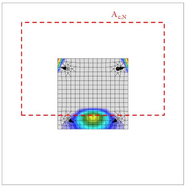
- \( A_{c,N} \) – betonkegel-uitbraakoppervlak voor een ankergroep
- \( A^{0}_{c,N} = (3.0 \, h_{ef})^2 \) – betonkegel-uitbraakoppervlak voor een enkel anker zonder randinvloed
- \(\psi_{s,N} = 0.7 + 0.3 \, \frac{c'}{c_{cr,N}} \leq 1\) – parameter gerelateerd aan de spanningsverdeling in het beton als gevolg van de nabijheid van het bevestigingsmiddel tot een rand van het betonstaaf
- \( c' \) – minimale afstand van het anker tot de rand
- \( c'_{cr,N} = 1.5 \, h_{ef} \) – karakteristieke randafstand voor het waarborgen van de overdracht van de karakteristieke weerstand van een anker bij betonuitbraak onder trekbelasting
- \(\psi_{re,N} = 0.5 + \frac{h_{emb}}{200} \leq 1\) – parameter die rekening houdt met het afsplinteren van de schil
- \( h_{emb} \) – inbeddiepte
- \(\psi_{ec,N} = \psi_{ec,N,x} \cdot \psi_{ec,N,y}\) – modificatiefactor voor ankergroepen die excentrisch op trek worden belast
- \(\psi_{ec,N,x} = \frac{1}{1 + \frac{2 e_{N,x}}{s_{cr,N}}}\), \(\psi_{ec,N,y} = \frac{1}{1 + \frac{2 e_{N,y}}{s_{cr,N}}}\) – modificatiefactoren in x- en y-richting
- \( e_{N,x}, e_{N,y} \) – belastingsexcentriciteiten
- \( s'_{cr,N} = 3.0 \, h_{ef} \) – karakteristieke ankerafstand om de karakteristieke weerstand van de ankers bij betonkegel bezwijken onder trekbelasting te waarborgen
- \(\psi_{M,N}\) – parameter die rekening houdt met het effect van een druk kracht tussen de bevestigingsplaat en het beton; \(\psi_{M,N}=1.0\) als aan een van de volgende criteria wordt voldaan:
- \(c' < 1.5 \cdot h_{ef}\) – het anker bevindt zich dicht bij de rand
- \( \frac{N_c^n}{N_{Ld}} < 0.8\)
- \(\frac{z}{h_{ef}} \ge 1.5\)
- \(N_c^n\) – druk kracht in de voetplaat
- \(N_{Ld} \) – som van de trekkrachten van ankers met een gemeenschappelijk betonkegel-uitbraakoppervlak
- \(\psi_{M,N} = 2- \frac{z}{h_{ef}} \ge 1 \) – anders
- \(z\) – inwendige hefboomarm
- \(\gamma_{Mc} = \gamma_c \cdot \gamma_{inst}\)
- \( \gamma_c \) – partiële veiligheidsfactor voor beton, aanpasbaar in de projectinstellingen
- \( \gamma_{inst} \) – installatieveiligheidsfactor, aanpasbaar in de projectinstellingen
Het betonkegel-uitbraakoppervlak voor een ankergroep belast op trek die een gemeenschappelijke betonkegel vormen, Ac,N, is weergegeven met een rode stippellijn.
Bezwijken van het staal bij afschuiving
Bezwijken van het staal bij afschuiving wordt bepaald conform Cl. 9.2.3. Er wordt aangenomen dat het anker is vervaardigd van een draadeind met dezelfde materiaaleigenschappen als bouten.
Afschuifkracht zonder hefboomarm
De afschuifweerstand wordt gecontroleerd conform IS 1946:2025 – 9.2.3.1:
\[V_{Rd,s} = \frac{V_{Rk,s}}{\gamma_{Ms}}\]
\[V_{Rk,s} = k_1 \cdot V^{0}_{Rk,s}\]
\[V^{0}_{Rk,s} = 0.5 \cdot A_s \cdot f_u\]
waarbij:
- \( V_{Rk,s} \) – karakteristieke weerstand van een bevestigingsmiddel bij bezwijken van het staal
- \( k_1 \) – productafhankelijke factor, aangenomen \( k_1 = 1\)
- \( V^{0}_{Rk,s} \) – de karakteristieke afschuifsterkte
- \( A_s \) – trekspanningsoppervlak
- \( f_u \) – treksterkte van de ankerbout
- \( \gamma_{Ms} \) – partiële veiligheidsfactor voor bezwijken van het staal bij afschuifbelasting
- \( \gamma_{Ms} = \frac{1.0 \, f_y}{f_u} \geq 1.25 \) voor \(f_u \le 800\) MPa en \(f_y/f_u \le 0.8\)
- \( \gamma_{Ms} = 1.5\) voor \(f_u > 800\) MPa of \(f_y/f_u > 0.8\)
- \( f_y \) – vloeigrens van de ankerbout
Afschuifkracht met hefboomarm
De afschuifweerstand wordt gecontroleerd conform IS 1946:2025 – 9.2.3.2:
\[V_{Rd,s} = \frac{V_{Rk,s}}{\gamma_{Ms}}\]
\[V_{Rk,s} = \frac{\alpha_M \cdot M_{Rk,s}}{l}\]
waarbij:
- \( V_{Rk,s} \) – karakteristieke weerstand van een bevestigingsmiddel bij bezwijken van het staal met hefboomarm
- \( \alpha_M \) – factor die rekening houdt met de mate van inklemming van het bevestigingsmiddel, aangenomen \( \alpha_M = 2\) omdat het anker is geklemd door twee moeren en de voetplaat stijver is dan het anker
- \( M_{Rk,s} = M^{0}_{Rk,s} \cdot \left( 1 - \frac{N_{Ld}}{N_{Rd,s}} \right) \) – karakteristieke buigsterkte van het bevestigingsmiddel beïnvloed door de normaalkracht
- \( N_{Ld} \) – rekenwaarde van de trekkracht
- \( N_{Rd,s} \) – treksterkte van een bevestigingsmiddel bij bezwijken van het staal
- \(M^{0}_{Rk,s} = 1.2 \cdot Z_{el} \cdot f_u\) – karakteristieke buigsterkte van het bevestigingsmiddel
- \( Z_{el} = \frac{\pi \, d_{a,r}^3}{32} \) – elastisch weerstandsmoment van het bevestigingsmiddel
- \( d_{a,r} \) – ankerdiameter verminderd door de schroefdraad
- \( f_u \) – treksterkte van de ankerbout
- \(l = 0.5 \cdot d_a + t_g + \frac{t_p}{2}\) – lengte van de hefboomarm
- \( d_a \) – ankerdiameter
- \( t_g \) – dikte van de cementdekvloer
- \( t_p \) – dikte van de voetplaat
- \( \gamma_{Ms} \) – partiële veiligheidsfactor voor bezwijken van het staal bij afschuifbelasting
- \( \gamma_{Ms} = \frac{1.0 \, f_y}{f_u} \geq 1.25 \) voor \(f_u \le 800\) MPa en \(f_y/f_u \le 0.8\)
- \( \gamma_{Ms} = 1.5\) voor \(f_u > 800\) MPa of \(f_y/f_u > 0.8\)
- \( f_y \) – vloeigrens van de ankerbout
Betonrandbreuk
De weerstand tegen betonrandbreuk wordt gecontroleerd conform IS 1946:2025 – 9.2.3.4. Als betonkegels van bevestigingsmiddelen elkaar overlappen, worden ze als groep gecontroleerd. De randen in de richting van de afschuifbelasting worden gecontroleerd. Alle belasting op een voetplaat wordt verondersteld te worden overgedragen door een bevestigingsmiddel nabij de gecontroleerde rand.
\[V_{Rd,c} = \frac{V_{Rk,c}}{\gamma_{Mc}}\]
\[V_{Rk,c} = V^{0}_{Rk,c} \cdot \frac{A_{c,V}}{A^{0}_{c,V}} \cdot \psi_{s,V} \cdot \psi_{re,V} \cdot \psi_{ec,V} \cdot \psi_{h,V} \cdot \psi_{\alpha,V}\]
waarbij
- \( V^{0}_{Rk,c} \) – beginwaarde van de karakteristieke afschuifsterkte van het bevestigingsmiddel
- \( V^{0}_{Rk,c} = 1.55 \cdot d_a^{\alpha} \cdot h_{ef}^{\beta} \cdot \sqrt{f_{ck}} \cdot (c'_1)^{1.5} \) voor gescheurd beton
- \( V^{0}_{Rk,c} = 2.18 \cdot d_a^{\alpha} \cdot h_{ef}^{\beta} \cdot \sqrt{f_{ck}} \cdot (c'_1)^{1.5} \) voor ongescheurd beton
- \( d_a \) – ankerdiameter
- \( \alpha = 0.1 \cdot \left( \frac{h_{ef}}{c'_1} \right)^{0.5} \) – factor
- \( h_{ef} = \min(h_{emb}, 20 \cdot d_a) \) – parameter gerelateerd aan de lengte van het bevestigingsmiddel
- \( h_{emb} \) – inbeddiepte
- \( \beta = 0.1 \cdot \left( \frac{d_a}{c'_1} \right)^{0.2} \) – factor
- \( f_{ck} \) – karakteristieke kubusdruksterkte van beton
- \( c'_1 \leq \max \left( \frac{c_{2,max}}{1.5}, \frac{D}{1.5}, \frac{s_{2,max}}{3} \right) \) – randafstand van het bevestigingsmiddel in richting 1 naar de rand in de belastingsrichting
- \( D \) – dikte van het betonstaaf
- \( c_{2,max} \) – de grootste van de twee afstanden tot de randen evenwijdig aan de belastingsrichting
- \( s_{2,max} \) – maximale tussenruimte in richting 2 tussen bevestigingsmiddelen binnen een groep
- \(A^{0}_{c,V} = 4.5 \cdot (c'_1)^2\) – referentie geprojecteerd oppervlak van de breukconus
- \( A_{c,V} \) – werkelijk oppervlak van het geïdealiseerde betonuitbraaklichaam
- \(\psi_{s,V} = 0.7 + 0.3 \cdot \frac{c'_2}{1.5 \cdot c'_1} \leq 1\) – parameter gerelateerd aan de spanningsverdeling in het beton als gevolg van de nabijheid van het bevestigingsmiddel tot een rand van het betonstaaf
- \( c'_1 \) – randafstand van het bevestigingsmiddel in richting 1 naar de rand in de belastingsrichting
- \( c'_2 \) – randafstand loodrecht op richting 1, zijnde de kleinste randafstand in een smal element met meerdere randafstanden
- \(\psi_{re,V} = 1.0\) – parameter die rekening houdt met het afsplinteren van de schil; er wordt aangenomen dat er geen randwapening of beugels aanwezig zijn
- \(\psi_{ec,V} = \frac{1}{1 + \frac{2 e_V}{3 \cdot c'_1}} \leq 1\) – modificatiefactor voor ankergroepen die excentrisch op afschuiving worden belast
- \( e_V \) – excentriciteit van de afschuifbelasting
- \( \psi_{h,V} = \left( \frac{1.5 \cdot c'_1}{D} \right)^{0.5} \geq 1 \) – modificatiefactor voor ankers in een ondiep betonstaaf
- \(\psi_{\alpha,V} = \sqrt{\frac{1}{(\cos \alpha_V)^2 + (0.5 \cdot \sin \alpha_V)^2}} \geq 1\) – modificatiefactor voor ankers belast onder een hoek met de betonrand
- \( \alpha_V \) – hoek tussen de aangebrachte belasting op het bevestigingsmiddel of de bevestigingsmiddelengroep en de richting loodrecht op de beschouwde vrije rand
- \(\gamma_{Mc} = \gamma_c \cdot \gamma_{inst}\) – partiële veiligheidsfactor voor bezwijken van het beton
- \( \gamma_c \) – partiële veiligheidsfactor voor beton
- \( \gamma_{inst} \) – installatieveiligheidsfactor van een ankersysteem bij afschuiving
Interactie van trek- en afschuifkrachten in staal
De interactie van trek- en afschuifkrachten in staal wordt uitgevoerd voor ankers met standoff: Direct conform IS 1946:2025 – 9.2.4:
\[\left( \frac{N_{Ld}}{N_{Rd,s}} \right)^2 + \left( \frac{V_{Ld}}{V_{Rd,s}} \right)^2 \leq 1.0\]
waarbij:
- \( N_{Ld} \) – rekenwaarde van de trekkracht
- \( N_{Rd,s} \) – treksterkte van het bevestigingsmiddel
- \( V_{Ld} \) – rekenwaarde van de afschuifkracht
- \( V_{Rd,s} \) – afschuifsterkte van het bevestigingsmiddel
Staalinteractie is niet vereist bij afschuifbelasting met hefboomarm. Dit wordt gedekt door de vergelijking voor afschuifbelasting met hefboomarm.
Interactie van trek- en afschuifkrachten in beton
De interactie van trek- en afschuifkrachten in beton wordt gecontroleerd conform IS 1946:2025 – 9.2.4:
\[\left( \frac{N_{Ld}}{N_{Rd,i}} \right)^{1.5} + \left( \frac{V_{Ld}}{V_{Rd,i}} \right)^{1.5} \leq 1.0\]
waarbij:
- \( \frac{N_{Ld}}{N_{Rd,i}} \) – de hoogste benuttingsgraad voor bezwijkmodi bij trek
- \( \frac{V_{Ld}}{V_{Rd,i}} \) – de hoogste benuttingsgraad voor bezwijkmodi bij afschuiving
- \( \frac{N_{Ld,g}}{N_{Rd,c}} \) – betonkegel-uitbraak van anker bij trek
- \( \frac{V_{Ld,g}}{V_{Rd,c}} \) – betonrandbreuk
Ankers met standoff: Speling
Ankers met standoff: speling bij trek worden ontworpen conform IS 1946:2025, en ankers bij druk worden ontworpen als een staafstaaf conform IS 800: 2007 met partiële veiligheidsfactor van ankers. De aangenomen lengte van de staaf is de som van de hoogte van de speling, de helft van de nominale diameter dikte en de helft van de voetplaatdikte. Standoff-ankers worden doorgaans gecontroleerd in een bouwfase vóór het injecteren.
Bezwijken van het staal bij trek wordt gecontroleerd conform IS 1946:2025 – 9.2.2.2:
\[N_{Rd,s} = \frac{N_{Rk,s}}{\gamma_{Ms}} \]
Bezwijken van het staal bij druk wordt gecontroleerd conform IS 800:2007 – 7.1:
\[P_d = A_s \cdot f_{cd}\]
waarbij:
- \( A_s \) – ankeroppervlak verminderd door de schroefdraad
- \( f_{cd} = \frac{\chi \cdot f_u}{\gamma_{Ms}} \) – rekenwaarde van de drukspanning
- \(\chi = \min \left( \frac{1}{\phi + \sqrt{\phi^2 - \lambda^2}}, 1 \right)\) – knikreductiefactor
- \(\phi = 0.5 \cdot \left[ 1 + \alpha \cdot (\lambda - 0.2) + \lambda^2 \right]\) – waarde ter bepaling van de knikreductiefactor
- \( \alpha \) – imperfectiefactor
- \(\lambda = \sqrt{\frac{f_u}{f_{cc}}}\) – relatieve slankheid
- \(f_{cc} = \frac{\pi^2 \cdot E}{\left( \frac{K L}{r} \right)^2}\) – Euler knikspanning
- \( E \) – elasticiteitsmodulus
- \(K L = 2 \cdot l\) – kniklengte
- \( l = 0.5 \cdot d_a + t_g + \frac{t_p}{2} \) – lengte van de hefboomarm
- \( d_a \) – ankerdiameter
- \( t_g \) – dikte van de cementdekvloer
- \( t_p \) – dikte van de voetplaat
- \(r = \sqrt{\frac{I}{A_s}}\) – traagheidsstraal van de ankerbout
- \( I = \frac{\pi \cdot d_{a,r}^4}{64} \) – traagheidsmoment van de bout
- \( d_{a,r} \) – ankerdiameter verminderd door de schroefdraad
- \(\gamma_{Ms} = \frac{1.2 \, f_y}{f_u} \geq 1.4 \) – partiële veiligheidsfactor voor bezwijken van het staal bij trekbelasting
- \( f_y \) – vloeigrens van de ankerbout
- \( f_u \) – treksterkte van de ankerbout
Afschuifweerstand wordt gecontroleerd conform IS 1946:2025 – 9.2.3.1:
\[V_{Rd,s} = \frac{V_{Rk,s}}{\gamma_{Ms}}\]
\[V_{Rk,s} = k_1 \cdot V^{0}_{Rk,s}\]
\[V^{0}_{Rk,s} = 0.5 \cdot A_s \cdot f_u\]
Buigweerstand wordt gecontroleerd conform IS 1946:2025 – 9.2.3.2:
\[M_{Rd,s} = \frac{M_{Rk,s}}{\gamma_{Ms}}\]
waarbij:
- \( M^{0}_{Rk,s} = 1.2 \cdot Z_{el} \cdot f_u \) – karakteristieke buigsterkte van het bevestigingsmiddel
- \( Z_{el} = \frac{\pi \cdot d_{a,r}^3}{32} \) – elastisch weerstandsmoment van het bevestigingsmiddel
- \( d_{a,r} \) – ankerdiameter verminderd door de schroefdraad
- \(\gamma_{Ms} = \frac{1.0 \, f_y}{f_u} \geq 1.25\)
- \( f_y \) – vloeigrens van de ankerbout
- \( f_u \) – treksterkte van de ankerbout
Interactie van belasting voor ankers op trek (IS 1946:2025 – 9.2.4):
\[\frac{N_{Ld}}{N_{Rd,s}} + \frac{M_{Ld}}{M_{Rd,s}} \leq 1.0\]
waarbij:
- \( N_{Ld} \) – rekenwaarde van de trekkracht
- \( N_{Rd,s} \) – rekenwaarde van de trekweerstand
- \( M_{Ld} \) – rekenwaarde van het buigend moment
- \( M_{Rd,s} \) – rekenwaarde van de buigweerstand
Interactie van belasting voor ankers op druk (IS 1946:2025 – 9.2.4):
\[\frac{P}{P_d} + \frac{M_{Ld}}{M_{Rd,s}} \leq 1.0\]
waarbij:
- \( P \) – rekenwaarde van de drukkracht
- \( P_d \) – rekenwaarde van de drukweerstand
- \( M_{Ld} \) – rekenwaarde van het buigend moment
- \( M_{Rd,s} \) – rekenwaarde van de buigweerstand
Betongebonden bezwijkmodi, inclusief hun interactie, worden gecontroleerd zoals voor de standaard ankers conform IS 1946:2025.
Detaillering
Als ankers met \(f_u \ge 1000\) MPa worden gebruikt, is de staalsterkte voor afschuifbelasting mogelijk niet nauwkeurig; gebruik in dat geval de staalsterkte uit AR.
Detaillering van bouten en lassen volgens Indiase norm
Bouten
Minimale boutafstand is volgens IS 800, Cl. 10.2.2: Hart op hart van de bout moet groter zijn dan \(2.5 \cdot d\), waarbij \(d\) de nominale boutdiameter is.
Minimale eind- en randafstanden gemeten vanuit de hartlijn van de bout worden aangehouden volgens IS 800, Cl. 10.2.4 als \(1.5 \cdot d_0\), waarbij \(d_0\) de standaard gatdiameter is volgens IS 800, Tabel 19.
De griplengte van bouten moet worden beperkt tot \(8d\) volgens IS 800, Cl. 10.3.3.2.
Lassen
Minimale lasgrootte wordt gecontroleerd volgens IS 800, Tabel 21:
| Dikte van het dikste deel [mm] | Minimale lasgrootte [mm] |
| \(t \le 10 \) | 3 |
| \( 10 < t \le 20 \) | 5 |
| \( 20 < t \le 32 \) | 6 |
| \( 32 < t \) | 10 |
Merk op dat de lasgrootte wordt aangenomen als keeldikte vermenigvuldigd met \(\sqrt{2}\).
Kolomvoet
De dikte van de kolomvoet moet groter zijn dan de dikte van de kolomflens volgens IS 800, Cl. 7.4.3.1.
Capaciteitsontwerp volgens Indiase Norm
Er wordt verwacht dat een plastische scharnier optreedt in het dissiperende element en alle niet-dissiperende elementen van de verbinding moeten de krachten als gevolg van de vloeiring in het dissiperende element veilig kunnen overdragen. Het dissiperende element is doorgaans een ligger in een momentvast raamwerk. De veiligheidsfactor wordt niet toegepast op dissiperende elementen:
Twee factoren worden toegewezen aan het dissiperende element:
- \(\gamma_{ov}\) – oversterkte factor – IS 800, Cl. 12; de aanbevolen waarde is \(\gamma_{ov} = 1.2\); aanpasbaar in materialen
- \(\gamma_{sh}\) – rek-verhardingsfactor; de aanbevolen waarde is \(\gamma_{sh} = 1.0\); aanpasbaar in bewerking
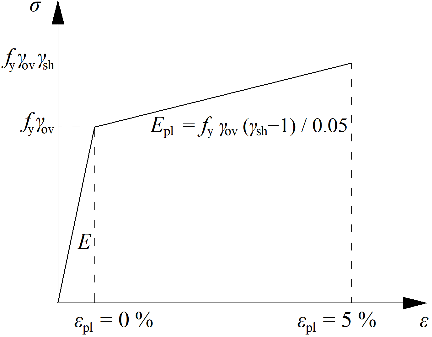
De verhoogde sterkte van het dissiperende element maakt het mogelijk belastingen in te voeren die ervoor zorgen dat het plastische scharnier optreedt in het dissiperende element. In het geval van een momentvast raamwerk met de ligger als dissiperend element, dient de ligger belast te worden met \(M_{y,Ed} = \gamma_{ov} \gamma_{sh} f_y W_{pl,y}\) en de bijbehorende dwarskracht \(V_{z,Ed} = -2 M_{y,Ed} / L_h\), waarbij:
- \(f_y\) – karakteristieke vloeispanning
- \(W_{pl,y}\) – plastisch weerstandsmoment
- \(L_h\) – afstand tussen plastische scharnieren op de ligger
In het geval van een asymmetrische verbinding dient de ligger belast te worden met zowel positieve als negatieve buigmomenten en de bijbehorende dwarskrachten.
De platen van dissiperende elementen zijn uitgesloten van de normtoetsing.
Classificatie op basis van stijfheid voor Indiase norm
Verbindingen worden geclassificeerd op basis van verbindingsstijfheid in:
- Stijf – verbindingen waarbij de oorspronkelijke hoeken tussen staven nauwelijks veranderen,
- Flexibel – verbindingen waarvan wordt aangenomen dat ze een betrouwbare en bekende mate van buigstijfheid kunnen leveren,
- Scharnierend – verbindingen die geen buigmomenten ontwikkelen.
Verbindingen worden geclassificeerd volgens EN 1993-1-8 – Cl. 5.2.2.
- Stijf – \( \frac{S_{j,ini} L_b}{E I_b} \ge k_b \)
- Flexibel – \( 0.5 < \frac{S_{j,ini} L_b}{E I_b} < k_b \)
- Scharnierend – \( \frac{S_{j,ini} L_b}{E I_b} \le 0.5 \)
waarbij:
- Sj,ini – beginstijfheid van de verbinding; de verbindingsstijfheid wordt als lineair beschouwd tot 2/3 van Mj,Rd
- Lb – theoretische lengte van de geanalyseerde staaf; ingesteld in de staaf-eigenschappen
- E – elasticiteitsmodulus van Young
- Ib – traagheidsmoment van de geanalyseerde staaf
- kb = 8 voor raamwerken waarbij het schoorwerk de horizontale verplaatsing met ten minste 80% vermindert; kb = 25 voor andere raamwerken, mits in elke verdieping Kb/Kc ≥ 0.1. De waarde kb = 25 wordt gebruikt tenzij de gebruiker "geschoord systeem" instelt in de Norminstellingen.
- Mj,Rd – rekenwaarde van de momentweerstand van de verbinding
- Kb = Ib / Lb
- Kc = Ic / Lc