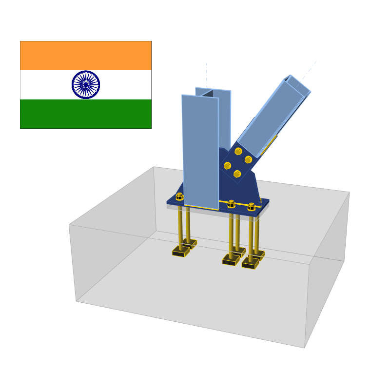
Vérification des composants d'assemblage acier (IS 800)
Vérification normative des platines selon la norme indienne
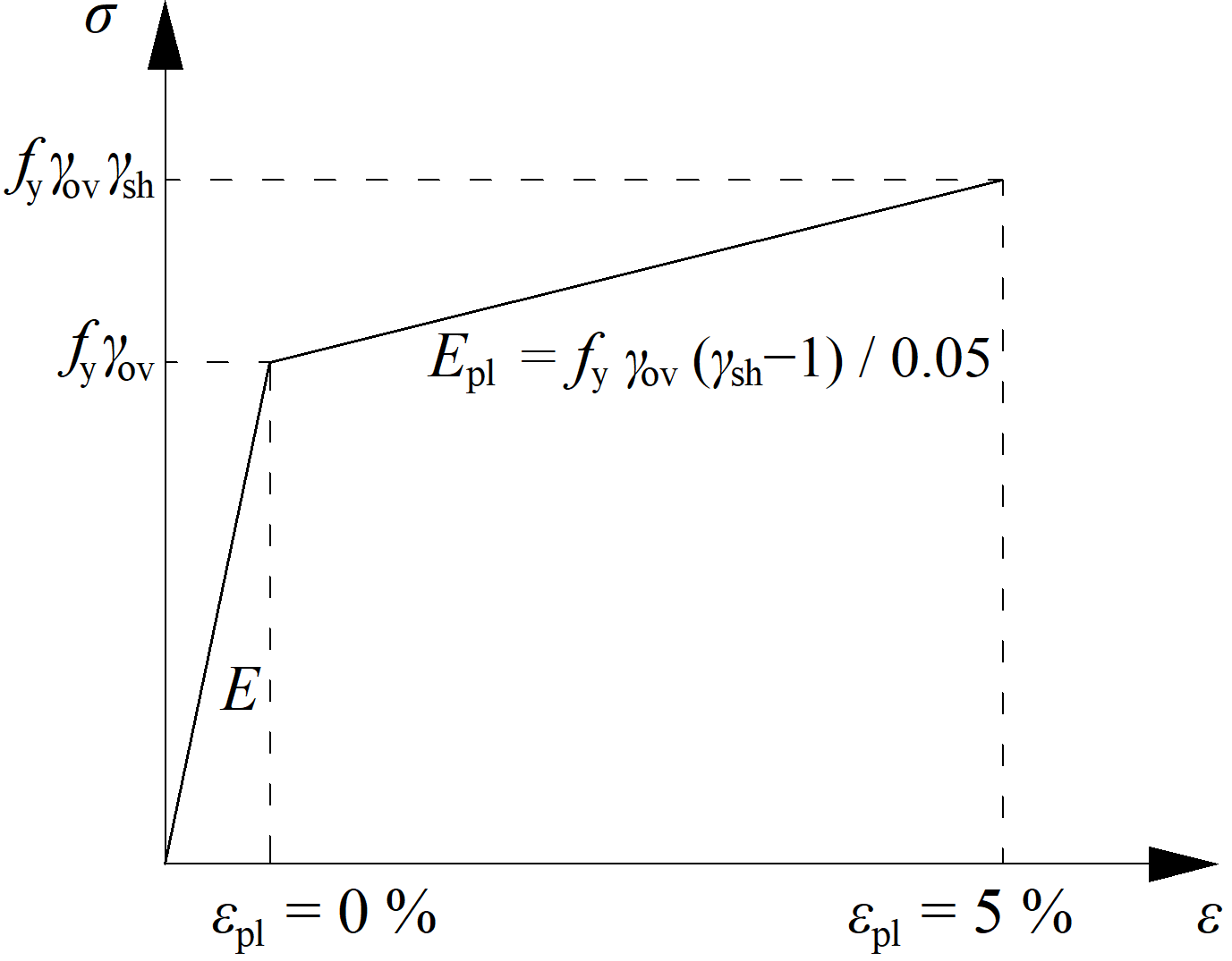
La contrainte équivalente résultante (HMH, von Mises) et la déformation plastique sont calculées sur les platines. Lorsque la limite d'élasticité de calcul, \( f_y / \gamma_{m0} \) (IS:800, Cl. 5.4.1), est atteinte sur le diagramme matériau bilinéaire, la vérification de la déformation plastique équivalente est effectuée. La valeur limite de 5 % est recommandée dans l'Eurocode (EN 1993-1-5 Ann. C, Par. C8, Note 1). Cette valeur peut être modifiée dans la configuration du code, mais les études de vérification ont été réalisées pour cette valeur recommandée.
L'élément de platine est divisé en 5 couches, et le comportement élastique/plastique est étudié dans chacune d'elles. Le programme affiche le résultat le plus défavorable parmi toutes les couches.
La contrainte peut être légèrement supérieure à la limite d'élasticité de calcul. La raison en est la légère inclinaison de la branche plastique du diagramme contrainte-déformation, qui est utilisée dans l'analyse pour améliorer la stabilité du calcul.
Vérification normative des soudures selon les normes indiennes
Soudures bout à bout
La vérification des soudures bout à bout à pleine pénétration n'est pas effectuée, car il est supposé qu'elles ont la même résistance que celle du profilé, à condition que le métal de base pour la soudure bout à bout soit supérieur à celui du profilé (IS 800:2007, 10.5.7.1.2).
Soudures d'angle
Les soudures d'angle sont vérifiées conformément à IS 800, Cl. 10.5.10.1.1 :
\[ f_e = \sqrt{f_a^2 + 3q^2} \le f_{wd} = \frac{f_u}{\sqrt{3} \gamma_{mw}} \]
où :
- \( f_e \) – contrainte équivalente dans la soudure
- \( f_a \) – contraintes normales, de compression ou de traction, dues à un effort axial ou à un moment fléchissant
- \( q \) – contrainte de cisaillement due à un effort tranchant ou à la traction
- \( f_{wd} \) – résistance de calcul d'une soudure d'angle
- \( f_u \) – la plus faible des contraintes ultimes de la soudure ou du métal de base ; la résistance ultime de l'électrode de soudage est supposée supérieure à celle du métal de base
- \( \gamma_{mw} \) – coefficient partiel de sécurité pour les soudures – IS 800, Tableau 5 ; modifiable dans la configuration du code
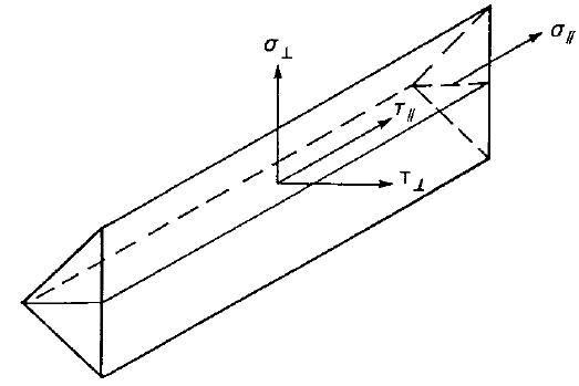
Les diagrammes de soudure affichent la contrainte selon la formule suivante :
\[ \sigma = \sqrt{\sigma_{\perp}^2 + \tau_{\perp}^2 + 3 \tau_{\parallel}^2 } \]
Vérification normative des boulons selon la norme indienne
Capacité de cisaillement des boulons
La résistance de calcul du boulon, \(V_{dsb}\), gouvernée par la résistance au cisaillement, est donnée par IS 800, Cl. 10.3.3 :
\[ V_{sb} \le V_{dsb} \]
où :
- \(V_{dsb} = V_{nsb}/\gamma_{mb}\) – capacité de cisaillement de calcul d'un boulon
- \(V_{nsb} = \frac{f_{ub}}{\sqrt{3}} A_e\) – capacité de cisaillement nominale d'un boulon
- \(f_{ub}\) – résistance ultime en traction du boulon ;
- \(A_e\) – aire résistant au cisaillement ; \(A_e = A_n\) pour un plan de cisaillement intercepté par les filets, \(A_e = A_s\) pour le cas où les filets ne se trouvent pas dans le plan de cisaillement
- \(A_n\) – aire nette de contrainte en traction du boulon
- \(A_s\) – aire de la section transversale au niveau du fût
- \(\gamma_{mb} = 1.25\) – coefficient partiel de sécurité pour les boulons – type appui – IS 800, Tableau 5 ; modifiable dans la configuration normative
Lorsque la longueur de serrage des boulons \(l_g\) (égale à l'épaisseur totale des plaques assemblées) est supérieure à \(5d\), la capacité de cisaillement de calcul \(V_{dsb}\) est réduite par un facteur \(\beta_{lg}\) – IS 800, Cl. 10.3.3.2 :
\[ \beta_{lg} = \frac{8}{3+l_g/d} \]
Selon IS 800, Cl. 10.3.3.3, la capacité de cisaillement de calcul des boulons transmettant le cisaillement à travers une plaque de remplissage d'épaisseur \(t_{pk} \ge 6\) mm doit être diminuée par un facteur :
\[ \beta_{pk} = (1-0.0125 t_{pk}) \]
Chaque plan de cisaillement est vérifié séparément et le résultat le plus défavorable est affiché.
Capacité en pression diamétrale des boulons
La résistance de calcul en pression diamétrale d'un boulon sur toute plaque, gouvernée par la pression diamétrale, est donnée par IS 800, Cl. 10.3.4 :
\[ V_{sb} \le V_{dpb} \]
où :
- \(V_{dpb} = V_{npb} / \gamma_{mb}\) – résistance de calcul en pression diamétrale d'un boulon
- \(V_{npb} = 2.5 k_b d t f_u\) – résistance nominale en pression diamétrale d'un boulon
- \(k_b = \min \left \{ \frac{e}{3d_0}, \, \frac{p}{3d_0}-0.25, \, \frac{f_{ub}}{f_u}, \, 1.0 \right \}\) – facteur pour la géométrie de l'assemblage et la résistance du matériau
- \(e\) – distance au bord de l'élément de fixation dans la direction de la pression diamétrale
- \(p\) – pas de l'élément de fixation dans la direction de la pression diamétrale
- \(f_{ub}\) – résistance ultime en traction du boulon
- \(f_u\) – résistance ultime en traction de la plaque
- \(d\) – diamètre nominal du boulon
- \(d_0\) – diamètre du trou de boulon
- \(t\) – épaisseur de la plaque
- \(\gamma_{mb} = 1.25\) – coefficient partiel de sécurité pour les boulons – type appui – IS 800, Tableau 5 ; modifiable dans la configuration normative
La pression diamétrale sur chaque plaque est vérifiée séparément et le résultat le plus défavorable est affiché.
La résistance en pression diamétrale est réduite pour les trous surdimensionnés et oblongs par un facteur :
- 0,7 – pour les trous surdimensionnés et les trous oblongs courts
- 0,5 – pour les trous oblongs longs
Les dimensions des trous surdimensionnés, oblongs courts et oblongs longs sont déterminées selon IS 800, Tableau 19.
Capacité en traction des boulons
Un boulon soumis à un effort de traction de calcul est vérifié selon IS 800, Cl. 10.3.5 :
\[ T_b \le T_{db} \]
où :
- \(T_{db} = T_{nb} / \gamma_{mb}\) – capacité en traction de calcul du boulon
- \(T_{nb} = \min \{ 0.9 f_{ub} A_n, \, f_{yb} A_s (\gamma_{mb} / \gamma_{m0}) \}\) – capacité en traction nominale du boulon
- \(f_{ub}\) – résistance ultime en traction du boulon
- \(f_{yb}\) – limite d'élasticité du boulon
- \(A_n\) – aire nette de contrainte en traction du boulon
- \(A_s\) – aire de la section transversale au niveau du fût
- \(\gamma_{mb} = 1.25\) – coefficient partiel de sécurité pour les boulons – type appui – IS 800, Tableau 5 ; modifiable dans la configuration normative
- \(\gamma_{m0} = 1.1\) – coefficient partiel de sécurité pour la résistance gouvernée par la plastification – IS 800, Tableau 5 ; modifiable dans la configuration normative
Boulon soumis à un cisaillement et une traction combinés
Un boulon devant résister simultanément à un effort de cisaillement de calcul et à un effort de traction de calcul doit, selon IS 800, Cl. 10.3.6, satisfaire :
\[ \left( \frac{V_{sb}}{V_{db}} \right)^2 + \left( \frac{T_{b}}{T_{db}} \right)^2 \le 1.0 \]
où :
- \(V_{sb}\) – effort de cisaillement de calcul
- \(V_{db} = \min \{ V_{dsb}, \, V_{dpb} \}\) – résistance de calcul au cisaillement du boulon – IS 800, Cl. 10.3.2
- \(V_{dsb}\) – résistance de calcul au cisaillement
- \(V_{dpb}\) – résistance de calcul en pression diamétrale
- \(T_b\) – effort de traction de calcul
- \(T_{db}\) – capacité en traction de calcul du boulon
Vérification normative des boulons préchargés selon les normes indiennes
Résistance au glissement
La résistance au glissement du boulon préchargé est vérifiée selon IS 800, Cl. 10.4.3 :
\[ V_{sf} \le V_{dsf} \]
où :
- \(V_{dsf} = V_{nsf} / \gamma_{mf}\) – capacité de cisaillement de calcul d'un boulon régie par le glissement pour un assemblage de type friction
- \(V_{nsf} = \mu_f n_e K_h F_0\) – capacité de cisaillement nominale d'un boulon régie par le glissement pour un assemblage de type friction
- \(\mu_f\) – coefficient de friction (facteur de glissement) tel que spécifié dans IS 800, Tableau 20 ; modifiable dans la configuration normative
- \(n_e = 1\) – nombre d'interfaces effectives offrant une résistance par friction au glissement ; chaque plan de cisaillement est vérifié séparément
- \(K_h\) – facteur pour les trous de boulons ; \(K_h = 1.0\) pour les éléments de fixation dans des trous standard, \(K_h = 0.85\) pour les éléments de fixation dans des trous surdimensionnés et des trous oblongs courts, \(K_h = 0.7\) pour les éléments de fixation dans des trous oblongs longs
- \(\gamma_{mf}\) – coefficient de sécurité partiel pour les boulons – type friction – IS 800, Tableau 5, \(\gamma_{mf}=1.10\) si la résistance au glissement est calculée à la charge de service, \(\gamma_{mf}= 1.25\) si la résistance au glissement est calculée à la charge ultime ; modifiable dans la configuration normative
- \(F_0 = A_n f_0\) – tension minimale du boulon (charge de preuve) à l'installation
- \(A_n\) – aire de la section nette en traction du boulon
- \(f_0 = 0.7 f_{ub}\) – contrainte de preuve
La capacité après glissement (IS 800, Cl. 10.4.4) doit être vérifiée en changeant le type de boulon de friction à appui – interaction traction/cisaillement pour la capacité de calcul à la charge ultime.
Capacité en traction des boulons
Un boulon soumis à un effort de traction factorisé est vérifié selon IS 800, Cl. 10.3.5 :
\[ T_f \le T_{df} \]
où :
- \(T_{df} = T_{nf} / \gamma_{mf}\) – capacité en traction de calcul du boulon à friction
- \(T_{nf} = \min \{ 0.9 f_{ub} A_n, \, f_{yb} A_s (\gamma_{mf} / \gamma_{m0}) \}\) – capacité en traction nominale du boulon à friction
- \(f_{ub}\) – résistance ultime en traction du boulon
- \(f_{yb}\) – limite d'élasticité du boulon
- \(A_n\) – aire de la section nette en traction du boulon
- \(A_s\) – aire de la section transversale au fût
- \(\gamma_{mf}\) – coefficient de sécurité partiel pour les boulons – type friction – IS 800, Tableau 5, \(\gamma_{mf}=1.10\) si la résistance au glissement est calculée à la charge de service, \(\gamma_{mf}= 1.25\) si la résistance au glissement est calculée à la charge ultime ; modifiable dans la configuration normative
- \(\gamma_{m0} = 1.1\) – coefficient de sécurité partiel pour la résistance régie par la plastification – IS 800, Tableau 5 ; modifiable dans la configuration normative
Les efforts de levier sont déterminés par analyse par éléments finis et sont inclus dans l'effort de traction.
Boulon à friction soumis à une combinaison de cisaillement et de traction
Un boulon devant résister simultanément à un effort de cisaillement de calcul et à un effort de traction de calcul doit, selon IS 800, Cl. 10.3.6, satisfaire :
\[ \left( \frac{V_{sf}}{V_{df}} \right)^2 + \left( \frac{T_{f}}{T_{df}} \right)^2 \le 1.0 \]
où :
- \(V_{sf}\) – cisaillement factorisé appliqué à la charge de calcul
- \(V_{df}\) – résistance au cisaillement de calcul
- \(T_f\) – traction factorisée appliquée extérieurement à la charge de calcul
- \(T_{df}\) – résistance en traction de calcul
Vérification normative du bloc de béton selon les normes indiennes
Béton en refoulement
Deux options pour la vérification du béton en refoulement sont disponibles :
- Selon IS 800, Cl. 7.4
- Selon IS 456, Cl. 34.4
Béton en refoulement vérifié selon IS 800, Cl. 7.4
La pression de refoulement maximale ne doit pas dépasser la résistance au refoulement égale à \(0.6 f_{ck}\), où \(f_{ck}\) est la résistance caractéristique en compression sur cube du béton. La résistance du coulis est supposée supérieure à celle du béton de fondation. La Cl. 7.4.3.1 fournit la formule pour l'épaisseur minimale des platines de base de poteau :
\[ t_s = \sqrt{2.5 w c^2 \gamma_{m0} / f_y} > t_f \]
où :
- \(w\) – pression uniforme exercée par le dessous sur la platine de base sous l'effort de compression axiale à l'état limite ultime
- \(c\) – débord de la platine de base par rapport au poteau
- \(f_y\) – limite d'élasticité de la platine de base
- \(t_f\) – épaisseur de la semelle du poteau
- \(\gamma_{m0} = 1.1\) – coefficient partiel de sécurité pour la résistance gouvernée par la plastification – IS 800, Tableau 5 ; modifiable dans la configuration normative
La formule peut être réécrite pour déterminer le débord en supposant que \(w = 0.6 f_{ck}\) :
\[ c = t_s \sqrt{\frac{f_y}{1.5 f_{ck} \gamma_{m0}}} \]
L'aire \(A_{c,eff}\) est déterminée en décalant la section transversale du poteau (avec raidisseurs) intersectant la platine de base d'un débord \(c\). Une autre aire, \(A_{FEM,eff}\), détermine la zone de contact entre la platine de base et la fondation en béton (coulis) par analyse par éléments finis. L'aire résistant aux efforts de compression, \(A_{eff}\), est l'intersection de ces deux aires, \(A_{c,eff}\) et \(A_{FEM,eff}\). La résistance au refoulement \(0.6 f_{ck}\) sur cette aire \(A_{eff}\) est supposée à l'état limite ultime.
La vérification du béton en refoulement est effectuée sous forme de contraintes :
\[ \sigma_c \le w \]
où :
- \(\sigma_c = \frac{N_c}{A_{eff}}\) – contrainte de refoulement moyenne sous la platine de base
- \(N_c\) – effort de compression
- \(w = 0.6 f_{ck}\) – résistance au refoulement du béton
Béton en refoulement vérifié selon IS 456, Cl. 34.4.
La pression de refoulement maximale ne doit pas dépasser la résistance au refoulement égale à \(0.45 f_{ck} \cdot \min \left \{ \sqrt{\frac{A_1}{A_2}}, \, 2 \right \} \), où :
- \(f_{ck}\) – résistance caractéristique en compression sur cube du béton ; la résistance du coulis est supposée supérieure à celle du béton de fondation
- \(A_1\) – aire d'appui prise comme l'aire de la base inférieure du plus grand tronc de pyramide ou de cône entièrement contenu dans la semelle, ayant pour base supérieure la surface effectivement chargée et une pente de côté d'un vertical pour deux horizontal
- \(A_2\) – aire de refoulement déterminée par analyse par éléments finis (égale à \(A_{FEM,eff}\))
La vérification du béton en refoulement est effectuée sous forme de contraintes :
\[ \sigma_c \le w \]
où :
- \(\sigma_c = \frac{N_c}{A_{2}}\) – contrainte de refoulement moyenne sous la platine de base
- \(N_c\) – effort de compression
- \(w = 0.45 f_{ck} \cdot \min \left \{ \sqrt{\frac{A_1}{A_2}}, \, 2 \right \}\) – résistance au refoulement du béton
Transfert de l'effort tranchant
L'effort tranchant à la platine de base est supposé être transféré du poteau à la fondation en béton par :
- Frottement entre la platine de base et le béton/coulis
- Bêche
- Boulons d'ancrage
Vérification normative des ancrages selon les normes indiennes
Les forces dans les ancrages, y compris les efforts de levier, sont déterminées par analyse par éléments finis, mais les résistances sont vérifiées à l'aide des dispositions normatives de la IS 1946:2025.
La vérification normative des ancrages est effectuée conformément à la IS 1946:2025. Bien que la norme ne fournisse pas spécifiquement certaines formules pour les ancrages coulés en place, les mêmes formules sont utilisées pour ces derniers. Cette approche est considérée comme conservative, car dans toutes les autres normes, telles que ACI 318 ou EN 1992-4, les ancrages coulés en place présentent une résistance légèrement supérieure à celle des ancrages post-installés.
Le béton fissuré ou non fissuré peut être sélectionné dans les paramètres du projet. Le béton fissuré est supposé par défaut de manière conservative. La vérification normative de l'éclatement du cône de béton en traction et en cisaillement peut être ignorée dans les paramètres du projet, ce qui signifie que la force est supposée être transmise par le ferraillage. L'utilisateur dispose de la valeur de cette force. En raison de l'utilisation de la résistance à l'éclatement du cône de béton dans la formule de vérification de la rupture par effet de levier du béton, cette vérification est également ignorée.
Les vérifications normatives suivantes des ancrages sollicités en traction ne sont pas fournies et doivent être effectuées à l'aide des informations figurant dans la Spécification Technique de Produit pertinente :
- Rupture par arrachement de l'élément de fixation (pour tous les ancrages),
- Rupture par éclatement latéral (pour les ancrages à tête),
- Rupture combinée par arrachement et cône de béton (pour les ancrages post-installés par scellement),
- Rupture par fendage du béton.
La rupture par effet de levier du béton en cisaillement n'est pas non plus fournie et doit être vérifiée à l'aide des informations figurant dans la Spécification Technique de Produit pertinente.
Rupture de l'acier en traction
La rupture de l'acier en traction est vérifiée conformément à la IS 1946:2025 – 9.2.2.2 :
\[N_{Rd,s} = \frac{N_{Rk,s}}{\gamma_{Ms}} \]
où :
- \( N_{Rk,s} = A_s \cdot f_u \) – résistance caractéristique d'un élément de fixation en cas de rupture de l'acier
- \( A_s \) – aire de la section résistante à la traction du boulon d'ancrage
- \( f_u \) – résistance ultime du boulon d'ancrage
- \(\gamma_{Ms} = \frac{1.2 \, f_y}{f_u} \geq 1.4 \) – coefficient partiel de sécurité pour la rupture de l'acier en traction
- \( f_y \) – limite d'élasticité du boulon d'ancrage
- \( f_u \) – résistance ultime du boulon d'ancrage
Résistance à l'éclatement du béton d'un ancrage en traction
La résistance à l'éclatement du béton d'un ancrage en traction est vérifiée conformément à la IS 1946:2025 – 9.2.2.3 et est fournie pour le groupe d'ancrages (le cas échéant). La résistance de calcul des éléments de fixation tendus dans un groupe ou d'un élément de fixation isolé est :
\[N_{Rd,c} = \frac{N_{Rk,c}}{\gamma_{Mc}}\]
\[N_{Rk,c} = N^{0}_{Rk,c} \cdot \frac{A_{c,N}}{A^{0}_{c,N}} \cdot \psi_{s,N} \cdot \psi_{re,N} \cdot \psi_{ec,N} \cdot \psi_{M,N}\]
où :
- \( N^{0}_{Rk,c} = 7.2 \, \sqrt{f_{ck}} \, h_{ef}^{1.5} \) pour le béton fissuré, \( N^{0}_{Rk,c} = 10.1 \, \sqrt{f_{ck}} \, h_{ef}^{1.5} \) pour le béton non fissuré – résistance caractéristique d'un élément de fixation, éloigné des effets des éléments de fixation adjacents ou des bords de l'élément en béton ; l'état du béton peut être défini dans les paramètres du projet
- \( f_{ck} \) – résistance caractéristique à la compression sur cube du béton
- \( h_{ef} = \min \left[ h_{emb}, \max\left( \frac{c_{max}}{1.5}, \frac{s_{max}}{3} \right) \right] \) – profondeur d'encastrement effective
- \(c_{\max}\) – distance maximale du centre de l'ancrage au bord de l'élément en béton
- \(s_{\max}\) – distance maximale entre axes des ancrages
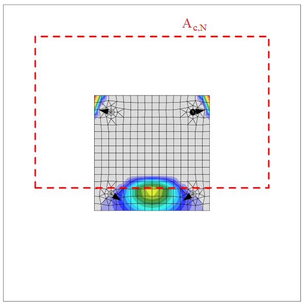
- \( A_{c,N} \) – aire du cône d'éclatement du béton pour un groupe d'ancrages
- \( A^{0}_{c,N} = (3.0 \, h_{ef})^2 \) – aire du cône d'éclatement du béton pour un ancrage isolé non influencé par les bords
- \(\psi_{s,N} = 0.7 + 0.3 \, \frac{c'}{c_{cr,N}} \leq 1\) – paramètre lié à la distribution des contraintes dans le béton en raison de la proximité de l'élément de fixation avec un bord de l'élément en béton
- \( c' \) – distance minimale de l'ancrage au bord
- \( c'_{cr,N} = 1.5 \, h_{ef} \) – distance au bord caractéristique garantissant la transmission de la résistance caractéristique d'un ancrage en cas d'éclatement du béton sous chargement en traction
- \(\psi_{re,N} = 0.5 + \frac{h_{emb}}{200} \leq 1\) – paramètre tenant compte de l'écaillage de la surface
- \( h_{emb} \) – profondeur d'encastrement
- \(\psi_{ec,N} = \psi_{ec,N,x} \cdot \psi_{ec,N,y}\) – facteur de modification pour les groupes d'ancrages chargés de manière excentrique en traction
- \(\psi_{ec,N,x} = \frac{1}{1 + \frac{2 e_{N,x}}{s_{cr,N}}}\), \(\psi_{ec,N,y} = \frac{1}{1 + \frac{2 e_{N,y}}{s_{cr,N}}}\) – facteurs de modification dans les directions x et y
- \( e_{N,x}, e_{N,y} \) – excentricités de charge
- \( s'_{cr,N} = 3.0 \, h_{ef} \) – entraxe caractéristique des ancrages pour garantir la résistance caractéristique des ancrages en cas de rupture par cône de béton sous charge de traction
- \(\psi_{M,N}\) – paramètre tenant compte de l'effet d'un effort de compression entre la platine et le béton ; \(\psi_{M,N}=1.0\) si l'un des critères suivants est satisfait :
- \(c' < 1.5 \cdot h_{ef}\) – l'ancrage est situé à proximité du bord
- \( \frac{N_c^n}{N_{Ld}} < 0.8\)
- \(\frac{z}{h_{ef}} \ge 1.5\)
- \(N_c^n\) – effort de compression dans la platine de base
- \(N_{Ld} \) – somme des efforts de traction des ancrages ayant une aire de cône d'éclatement commune
- \(\psi_{M,N} = 2- \frac{z}{h_{ef}} \ge 1 \) – sinon
- \(z\) – bras de levier interne
- \(\gamma_{Mc} = \gamma_c \cdot \gamma_{inst}\)
- \( \gamma_c \) – coefficient partiel de sécurité pour le béton, modifiable dans les paramètres du projet
- \( \gamma_{inst} \) – coefficient partiel de sécurité lié à la mise en œuvre, modifiable dans les paramètres du projet
L'aire du cône d'éclatement du béton pour un groupe d'ancrages sollicités en traction formant un cône de béton commun, Ac,N, est représentée par un trait discontinu rouge.
Rupture de l'acier en cisaillement
La rupture de l'acier en cisaillement est déterminée conformément à l'article 9.2.3. Il est supposé que l'ancrage est constitué d'une tige filetée avec les mêmes propriétés matérielles que les boulons.
Effort de cisaillement sans bras de levier
La résistance au cisaillement est vérifiée conformément à la IS 1946:2025 – 9.2.3.1 :
\[V_{Rd,s} = \frac{V_{Rk,s}}{\gamma_{Ms}}\]
\[V_{Rk,s} = k_1 \cdot V^{0}_{Rk,s}\]
\[V^{0}_{Rk,s} = 0.5 \cdot A_s \cdot f_u\]
où :
- \( V_{Rk,s} \) – résistance caractéristique d'un élément de fixation en cas de rupture de l'acier
- \( k_1 \) – facteur dépendant du produit, supposé \( k_1 = 1\)
- \( V^{0}_{Rk,s} \) – résistance caractéristique au cisaillement
- \( A_s \) – aire de la section résistante à la traction
- \( f_u \) – résistance ultime du boulon d'ancrage
- \( \gamma_{Ms} \) – coefficient partiel de sécurité pour la rupture de l'acier sous chargement en cisaillement
- \( \gamma_{Ms} = \frac{1.0 \, f_y}{f_u} \geq 1.25 \) pour \(f_u \le 800\) MPa et \(f_y/f_u \le 0.8\)
- \( \gamma_{Ms} = 1.5\) pour \(f_u > 800\) MPa ou \(f_y/f_u > 0.8\)
- \( f_y \) – limite d'élasticité du boulon d'ancrage
Effort de cisaillement avec bras de levier
La résistance au cisaillement est vérifiée conformément à la IS 1946:2025 – 9.2.3.2 :
\[V_{Rd,s} = \frac{V_{Rk,s}}{\gamma_{Ms}}\]
\[V_{Rk,s} = \frac{\alpha_M \cdot M_{Rk,s}}{l}\]
où :
- \( V_{Rk,s} \) – résistance caractéristique d'un élément de fixation en cas de rupture de l'acier avec bras de levier
- \( \alpha_M \) – facteur tenant compte du degré d'encastrement de l'élément de fixation, supposé \( \alpha_M = 2\) car l'ancrage est bloqué par deux écrous et la platine de base est plus rigide que l'ancrage
- \( M_{Rk,s} = M^{0}_{Rk,s} \cdot \left( 1 - \frac{N_{Ld}}{N_{Rd,s}} \right) \) – résistance caractéristique à la flexion de l'élément de fixation influencée par l'effort axial
- \( N_{Ld} \) – effort de traction de calcul
- \( N_{Rd,s} \) – résistance à la traction d'un élément de fixation en cas de rupture de l'acier
- \(M^{0}_{Rk,s} = 1.2 \cdot Z_{el} \cdot f_u\) – résistance caractéristique à la flexion de l'élément de fixation
- \( Z_{el} = \frac{\pi \, d_{a,r}^3}{32} \) – module d'inertie élastique de l'élément de fixation
- \( d_{a,r} \) – diamètre de l'ancrage réduit par les filets
- \( f_u \) – résistance ultime du boulon d'ancrage
- \(l = 0.5 \cdot d_a + t_g + \frac{t_p}{2}\) – longueur du bras de levier
- \( d_a \) – diamètre de l'ancrage
- \( t_g \) – épaisseur de la couche de mortier de scellement
- \( t_p \) – épaisseur de la platine de base
- \( \gamma_{Ms} \) – coefficient partiel de sécurité pour la rupture de l'acier sous chargement en cisaillement
- \( \gamma_{Ms} = \frac{1.0 \, f_y}{f_u} \geq 1.25 \) pour \(f_u \le 800\) MPa et \(f_y/f_u \le 0.8\)
- \( \gamma_{Ms} = 1.5\) pour \(f_u > 800\) MPa ou \(f_y/f_u > 0.8\)
- \( f_y \) – limite d'élasticité du boulon d'ancrage
Rupture du béton en bord de dalle
La résistance à la rupture du béton en bord de dalle est vérifiée conformément à la IS 1946:2025 – 9.2.3.4. Si les cônes de béton des éléments de fixation se recoupent, ils sont vérifiés en tant que groupe. Les bords dans la direction de la charge de cisaillement sont vérifiés. L'ensemble de la charge appliquée à une platine de base est supposé être transmis par un élément de fixation proche du bord vérifié.
\[V_{Rd,c} = \frac{V_{Rk,c}}{\gamma_{Mc}}\]
\[V_{Rk,c} = V^{0}_{Rk,c} \cdot \frac{A_{c,V}}{A^{0}_{c,V}} \cdot \psi_{s,V} \cdot \psi_{re,V} \cdot \psi_{ec,V} \cdot \psi_{h,V} \cdot \psi_{\alpha,V}\]
où
- \( V^{0}_{Rk,c} \) – valeur initiale de la résistance caractéristique au cisaillement de l'élément de fixation
- \( V^{0}_{Rk,c} = 1.55 \cdot d_a^{\alpha} \cdot h_{ef}^{\beta} \cdot \sqrt{f_{ck}} \cdot (c'_1)^{1.5} \) pour le béton fissuré
- \( V^{0}_{Rk,c} = 2.18 \cdot d_a^{\alpha} \cdot h_{ef}^{\beta} \cdot \sqrt{f_{ck}} \cdot (c'_1)^{1.5} \) pour le béton non fissuré
- \( d_a \) – diamètre de l'ancrage
- \( \alpha = 0.1 \cdot \left( \frac{h_{ef}}{c'_1} \right)^{0.5} \) – facteur
- \( h_{ef} = \min(h_{emb}, 20 \cdot d_a) \) – paramètre lié à la longueur de l'élément de fixation
- \( h_{emb} \) – profondeur d'encastrement
- \( \beta = 0.1 \cdot \left( \frac{d_a}{c'_1} \right)^{0.2} \) – facteur
- \( f_{ck} \) – résistance caractéristique à la compression sur cube du béton
- \( c'_1 \leq \max \left( \frac{c_{2,max}}{1.5}, \frac{D}{1.5}, \frac{s_{2,max}}{3} \right) \) – distance au bord de l'élément de fixation dans la direction 1 vers le bord dans la direction de chargement
- \( D \) – épaisseur de l'élément en béton
- \( c_{2,max} \) – la plus grande des deux distances aux bords parallèles à la direction de chargement
- \( s_{2,max} \) – entraxe maximal dans la direction 2 entre les éléments de fixation d'un groupe
- \(A^{0}_{c,V} = 4.5 \cdot (c'_1)^2\) – aire projetée de référence du cône de rupture
- \( A_{c,V} \) – aire réelle du corps d'éclatement idéalisé du béton
- \(\psi_{s,V} = 0.7 + 0.3 \cdot \frac{c'_2}{1.5 \cdot c'_1} \leq 1\) – paramètre lié à la distribution des contraintes dans le béton en raison de la proximité de l'élément de fixation avec un bord de l'élément en béton
- \( c'_1 \) – distance au bord de l'élément de fixation dans la direction 1 vers le bord dans la direction de chargement
- \( c'_2 \) – distance au bord perpendiculaire à la direction 1, qui est la plus petite distance au bord dans un élément étroit avec plusieurs distances aux bords
- \(\psi_{re,V} = 1.0\) – paramètre tenant compte de l'effet d'écaillage de la surface, aucun ferraillage de bord ni étrier n'est supposé
- \(\psi_{ec,V} = \frac{1}{1 + \frac{2 e_V}{3 \cdot c'_1}} \leq 1\) – facteur de modification pour les groupes d'ancrages chargés de manière excentrique en cisaillement
- \( e_V \) – excentricité de la charge de cisaillement
- \( \psi_{h,V} = \left( \frac{1.5 \cdot c'_1}{D} \right)^{0.5} \geq 1 \) – facteur de modification pour les ancrages situés dans un élément en béton de faible épaisseur
- \(\psi_{\alpha,V} = \sqrt{\frac{1}{(\cos \alpha_V)^2 + (0.5 \cdot \sin \alpha_V)^2}} \geq 1\) – facteur de modification pour les ancrages chargés selon un angle par rapport au bord du béton
- \( \alpha_V \) – angle entre la charge appliquée à l'élément de fixation ou au groupe d'éléments de fixation et la direction perpendiculaire au bord libre considéré
- \(\gamma_{Mc} = \gamma_c \cdot \gamma_{inst}\) – coefficient partiel de sécurité pour la rupture du béton
- \( \gamma_c \) – coefficient partiel de sécurité pour le béton
- \( \gamma_{inst} \) – coefficient partiel de sécurité lié à la mise en œuvre d'un système d'ancrage en cisaillement
Interaction des efforts de traction et de cisaillement dans l'acier
L'interaction des efforts de traction et de cisaillement dans l'acier est effectuée pour les ancrages avec saillie : Directe conformément à la IS 1946:2025 – 9.2.4 :
\[\left( \frac{N_{Ld}}{N_{Rd,s}} \right)^2 + \left( \frac{V_{Ld}}{V_{Rd,s}} \right)^2 \leq 1.0\]
où :
- \( N_{Ld} \) – effort de traction de calcul
- \( N_{Rd,s} \) – résistance à la traction de l'élément de fixation
- \( V_{Ld} \) – effort de cisaillement de calcul
- \( V_{Rd,s} \) – résistance au cisaillement de l'élément de fixation
La vérification de l'interaction dans l'acier n'est pas requise en cas de charge de cisaillement avec bras de levier. Elle est couverte par l'équation de la charge de cisaillement avec bras de levier.
Interaction des efforts de traction et de cisaillement dans le béton
L'interaction des efforts de traction et de cisaillement dans le béton est vérifiée conformément à la IS 1946:2025 – 9.2.4 :
\[\left( \frac{N_{Ld}}{N_{Rd,i}} \right)^{1.5} + \left( \frac{V_{Ld}}{V_{Rd,i}} \right)^{1.5} \leq 1.0\]
où :
- \( \frac{N_{Ld}}{N_{Rd,i}} \) – la valeur de taux de travail la plus élevée pour les modes de rupture en traction
- \( \frac{V_{Ld}}{V_{Rd,i}} \) – la valeur de taux de travail la plus élevée pour les modes de rupture en cisaillement
- \( \frac{N_{Ld,g}}{N_{Rd,c}} \) – rupture par éclatement du béton d'un ancrage en traction
- \( \frac{V_{Ld,g}}{V_{Rd,c}} \) – rupture du béton en bord de dalle
Ancrages avec saillie : Jeu
Les ancrages avec saillie : jeu en traction sont dimensionnés conformément à la IS 1946:2025, et les ancrages en compression sont dimensionnés comme un élément de type poutre conformément à la IS 800: 2007 avec le coefficient partiel de sécurité des ancrages. La longueur supposée de l'élément est la somme de la hauteur du jeu, de la moitié de l'épaisseur du diamètre nominal et de la moitié de l'épaisseur de la platine de base. Les ancrages avec saillie sont généralement vérifiés au stade de la construction avant le scellement.
La rupture de l'acier en traction est vérifiée conformément à la IS 1946:2025 – 9.2.2.2 :
\[N_{Rd,s} = \frac{N_{Rk,s}}{\gamma_{Ms}} \]
La rupture de l'acier en compression est vérifiée conformément à la IS 800:2007 – 7.1 :
\[P_d = A_s \cdot f_{cd}\]
où :
- \( A_s \) – aire de la section de l'ancrage réduite par les filets
- \( f_{cd} = \frac{\chi \cdot f_u}{\gamma_{Ms}} \) – contrainte de compression de calcul
- \(\chi = \min \left( \frac{1}{\phi + \sqrt{\phi^2 - \lambda^2}}, 1 \right)\) – facteur de réduction au flambement
- \(\phi = 0.5 \cdot \left[ 1 + \alpha \cdot (\lambda - 0.2) + \lambda^2 \right]\) – valeur permettant de déterminer le facteur de réduction au flambement
- \( \alpha \) – facteur d'imperfection
- \(\lambda = \sqrt{\frac{f_u}{f_{cc}}}\) – élancement relatif
- \(f_{cc} = \frac{\pi^2 \cdot E}{\left( \frac{K L}{r} \right)^2}\) – contrainte critique d'Euler
- \( E \) – module d'élasticité
- \(K L = 2 \cdot l\) – longueur de flambement
- \( l = 0.5 \cdot d_a + t_g + \frac{t_p}{2} \) – longueur du bras de levier
- \( d_a \) – diamètre de l'ancrage
- \( t_g \) – épaisseur de la couche de mortier de scellement
- \( t_p \) – épaisseur de la platine de base
- \(r = \sqrt{\frac{I}{A_s}}\) – rayon de giration du boulon d'ancrage
- \( I = \frac{\pi \cdot d_{a,r}^4}{64} \) – moment d'inertie du boulon
- \( d_{a,r} \) – diamètre de l'ancrage réduit par les filets
- \(\gamma_{Ms} = \frac{1.2 \, f_y}{f_u} \geq 1.4 \) – coefficient partiel de sécurité pour la rupture de l'acier sous chargement en traction
- \( f_y \) – limite d'élasticité du boulon d'ancrage
- \( f_u \) – résistance ultime du boulon d'ancrage
La résistance au cisaillement est vérifiée conformément à la IS 1946:2025 – 9.2.3.1 :
\[V_{Rd,s} = \frac{V_{Rk,s}}{\gamma_{Ms}}\]
\[V_{Rk,s} = k_1 \cdot V^{0}_{Rk,s}\]
\[V^{0}_{Rk,s} = 0.5 \cdot A_s \cdot f_u\]
La résistance à la flexion est vérifiée conformément à la IS 1946:2025 – 9.2.3.2 :
\[M_{Rd,s} = \frac{M_{Rk,s}}{\gamma_{Ms}}\]
où :
- \( M^{0}_{Rk,s} = 1.2 \cdot Z_{el} \cdot f_u \) – résistance caractéristique à la flexion de l'élément de fixation
- \( Z_{el} = \frac{\pi \cdot d_{a,r}^3}{32} \) – module d'inertie élastique de l'élément de fixation
- \( d_{a,r} \) – diamètre de l'ancrage réduit par les filets
- \(\gamma_{Ms} = \frac{1.0 \, f_y}{f_u} \geq 1.25\)
- \( f_y \) – limite d'élasticité du boulon d'ancrage
- \( f_u \) – résistance ultime du boulon d'ancrage
Interaction des sollicitations pour les ancrages en traction (IS 1946:2025 – 9.2.4) :
\[\frac{N_{Ld}}{N_{Rd,s}} + \frac{M_{Ld}}{M_{Rd,s}} \leq 1.0\]
où :
- \( N_{Ld} \) – effort de traction de calcul
- \( N_{Rd,s} \) – résistance à la traction de calcul
- \( M_{Ld} \) – moment fléchissant de calcul
- \( M_{Rd,s} \) – résistance à la flexion de calcul
Interaction des sollicitations pour les ancrages en compression (IS 1946:2025 – 9.2.4) :
\[\frac{P}{P_d} + \frac{M_{Ld}}{M_{Rd,s}} \leq 1.0\]
où :
- \( P \) – effort de compression de calcul
- \( P_d \) – résistance à la compression de calcul
- \( M_{Ld} \) – moment fléchissant de calcul
- \( M_{Rd,s} \) – résistance à la flexion de calcul
Les modes de rupture liés au béton, y compris leur interaction, sont vérifiés comme pour les ancrages standard conformément à la IS 1946:2025.
Dispositions constructives
Si des ancrages avec \(f_u \ge 1000\) MPa sont utilisés, la résistance de l'acier sous charge de cisaillement peut ne pas être précise ; utiliser la résistance de l'acier issue de l'AR à la place.
Détail des boulons et des soudures selon la norme indienne
Boulons
L'espacement minimal des boulons est conforme à IS 800, Cl. 10.2.2 : l'entraxe des boulons doit être supérieur à \(2.5 \cdot d\), où \(d\) est le diamètre nominal du boulon.
Les distances minimales de rive et de bord mesurées depuis l'axe du boulon sont prises conformément à IS 800, Cl. 10.2.4 comme \(1.5 \cdot d_0\), où \(d_0\) est le diamètre de trou standard selon IS 800, Tableau 19.
La longueur de prise des boulons doit être limitée à \(8d\) conformément à IS 800, Cl. 10.3.3.2.
Soudures
La taille minimale des soudures est vérifiée conformément à IS 800, Tableau 21 :
| Épaisseur de la partie la plus épaisse [mm] | Taille minimale de soudure [mm] |
| \(t \le 10 \) | 3 |
| \( 10 < t \le 20 \) | 5 |
| \( 20 < t \le 32 \) | 6 |
| \( 32 < t \) | 10 |
Notez que la taille de la soudure est supposée être l'épaisseur de gorge multipliée par \(\sqrt{2}\).
Platine de base de poteau
L'épaisseur de la platine de base du poteau doit être supérieure à l'épaisseur de la semelle du poteau conformément à IS 800, Cl. 7.4.3.1.
Calcul en capacité selon la norme indienne
La rotule plastique est censée apparaître dans l'élément dissipatif et tous les éléments non dissipatifs de l'assemblage doivent être capables de transférer en toute sécurité les efforts dus à la plastification de l'élément dissipatif. L'élément dissipatif est généralement une poutre dans un portique à nœuds rigides. Le coefficient de sécurité n'est pas utilisé pour les éléments dissipatifs :
Deux facteurs sont attribués à l'élément dissipatif :
- \(\gamma_{ov}\) – facteur de sur-résistance – IS 800, Cl. 12 ; la valeur recommandée est \(\gamma_{ov} = 1.2\) ; modifiable dans les matériaux
- \(\gamma_{sh}\) – facteur d'écrouissage ; la valeur recommandée est \(\gamma_{sh} = 1.0\) ; modifiable dans l'opération
La résistance accrue de l'élément dissipatif permet l'introduction de charges qui provoquent l'apparition de la rotule plastique dans l'élément dissipatif. Dans le cas d'un portique à nœuds rigides avec une poutre comme élément dissipatif, la poutre doit être chargée par \(M_{y,Ed} = \gamma_{ov} \gamma_{sh} f_y W_{pl,y}\) et l'effort tranchant correspondant \(V_{z,Ed} = -2 M_{y,Ed} / L_h\), où :
- \(f_y\) – limite d'élasticité caractéristique
- \(W_{pl,y}\) – module plastique de la section
- \(L_h\) – distance entre les rotules plastiques sur la poutre
Dans le cas d'un assemblage asymétrique, la poutre doit être chargée par des moments fléchissants positifs et négatifs ainsi que par leurs efforts tranchants correspondants.
Les plaques des éléments dissipatifs sont exclues de la vérification normative.
Classification selon la rigidité selon la norme indienne
Les assemblages sont classifiés selon la rigidité de l'assemblage en :
- Rigide – assemblages avec une variation insignifiante des angles initiaux entre les éléments,
- Semi-rigide – assemblages supposés avoir la capacité de fournir un degré de retenue en flexion fiable et connu,
- Articulé – assemblages qui ne développent pas de moments fléchissants.
Les assemblages sont classifiés selon EN 1993-1-8 – Art. 5.2.2.
- Rigide – \( \frac{S_{j,ini} L_b}{E I_b} \ge k_b \)
- Semi-rigide – \( 0.5 < \frac{S_{j,ini} L_b}{E I_b} < k_b \)
- Articulé – \( \frac{S_{j,ini} L_b}{E I_b} \le 0.5 \)
où :
- Sj,ini – rigidité initiale de l'assemblage ; la rigidité de l'assemblage est supposée linéaire jusqu'aux 2/3 de Mj,Rd
- Lb – longueur théorique de l'élément analysé ; définie dans les propriétés de l'élément
- E – module d'élasticité de Young
- Ib – moment d'inertie de l'élément analysé
- kb = 8 pour les portiques où le système de contreventement réduit le déplacement horizontal d'au moins 80 % ; kb = 25 pour les autres portiques, à condition que dans chaque niveau Kb/Kc ≥ 0,1. La valeur kb = 25 est utilisée sauf si l'utilisateur définit « système contreventé » dans la configuration normative.
- Mj,Rd – valeur de calcul de la résistance en moment de l'assemblage
- Kb = Ib / Lb
- Kc = Ic / Lc