Zoals beschreven in Inwendige krachten in het hoofdstuk Transformatie van herberekende inwendige krachten naar het zwaartepunt van de doorsnede, worden oppervlaktedimensioneringskrachten getransformeerd naar het zwaartepunt van een 2D-elementdoorsnede. Het resultaat van deze transformatie is een buigend moment en een normaalkracht, werkend in het zwaartepunt van een rechthoekige doorsnede, waarbij de kantlengte 1 m is en de hoogte overeenkomt met de dikte van de plaat.
De normtoetsingen van het 2D-element worden in alle gedefinieerde richtingen tegelijk uitgevoerd. Het programma converteert de wapening automatisch naar de toetsingsrichting met behulp van de formule:
\[{{A}_{Si,\alpha }}={{A}_{S}}\cdot {{\cos }^{2}}({{\alpha }_{i}})\]
| Beschrijving | |
| Asi,a | Het oppervlak van de ide waperingslaag herberekend naar richting a |
| As | Het oppervlak van de ide waperingslaag van het 2D-element |
| αi | De hoek tussen de ide waperingslaag en de toetsingsrichting |
| Opmerking: |
| Verdelingswapening in 2D-elementen van het type plaat en schaal-plaat wordt alleen meegenomen in de constructieve bepalingentoets; deze wordt niet gebruikt in andere 2D-elementtoetsingen. |
Resultaten van normtoetsingen in gedefinieerde richtingen
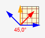
Alle ingeschakelde normtoetsingen worden automatisch in alle vereiste richtingen uitgevoerd. De presentatie van resultaten is vergelijkbaar met de presentatie van resultaten van 1D-elementen. De presentatie voor 2D-elementen maakt het mogelijk de te presenteren richting in te stellen. Resultaten voor 2D-elementen worden gepresenteerd in toetsingsrichtingen. Alle richtingen waarin de normtoetsingen zijn berekend, worden weergegeven in de grafische presentatie.
De pijlen in de afbeelding vertegenwoordigen toetsingsrichtingen, waarbij oranje de richting van de maximale toetsingswaarde is en rood de huidige toetsingsrichting. Om de huidige richting te wijzigen, klikt u op de pijl of op de bijbehorende knop in het lint.
| Opmerking: |
| Na afloop van de berekening worden de toetsingsrichtingen in alle normtoetsingen ingesteld op de richting van de maximale benuttingsgraad van de doorsnede. |
Resultaten in afzonderlijke normtoetsingen worden gepresenteerd in de huidige richting. De hoek van de normtoetsing wordt boven de tabel met de toetsingssamenvatting weergegeven.
De resultaten in de maatgevende richting worden afgedrukt in het rapport.
Uiterste grenstoestand
De principes van UGT-normtoetsingen zijn beschreven in het theoretische achtergrondhandboek voor 1D-elementen. Alleen de verschillen voor 2D-elementen worden beschreven in de volgende hoofdstukken.
Capaciteitstoets
De capaciteitstoets verschilt niet van de normtoetsingen voor 1D-elementen. De belasting werkt slechts in één vlak, zodat het toetsingstype N + M is.
Responstoets
De responstoetsingen voor afzonderlijke toetsingsrichtingen gebruiken dezelfde algoritmen als de normtoetsingen van 1D-elementen.
Interactietoets
Anders dan bij 1D-elementen wordt de interactietoets alleen uitgevoerd om de benutting V + M te evalueren, de interactie van afschuiving en buigend moment. De waarden VRd,c en VRd,max kunnen worden geverifieerd in de samenvattingstabel van de interactietoets.
Vergelijking van capaciteitstoets tussen IDEA Concrete, RFEM en SCIA Engineer
Om de capaciteitstoetsresultaten te vergelijken met RFEM en SCIA Engineer werden dezelfde gegevens gebruikt als beschreven in Inwendige krachten in het hoofdstuk Vergelijking van berekening van inwendige krachten met de programma's RFEM en SCIA Engineer. De vergelijking werd uitgevoerd in twee punten van de plaat.
Omdat de programma's RFEM en SEN de werkelijke wapening in de plaat niet toetsen, maar alleen het benodigde waperingsoppervlak ontwerpen, werden twee methoden gebruikt om de berekening te vergelijken. De eerste methode vergelijkt de benuttingsgraad van de doorsnede voor de vereiste wapening ontworpen in RFEM en SEN, ervan uitgaande dat de doorsnede tot 100% wordt benut wanneer het berekende vereiste waperingsoppervlak wordt gebruikt.
De benuttingsgraad van de doorsnede gewapend in IDEA Concrete kan dan relatief worden uitgedrukt.
Relatieve benuttingsgraad = As, req / As, RCS × 100 [%]
| Beschrijving | |
| As, req | Vereist waperingsoppervlak berekend in RFEM of SEN |
| As, RCS | Waperingsoppervlak in IDEA Concrete |
| 100 [%] | Percentage |
De doorsnede in IDEA Concrete werd aan de onderzijde gewapend met wapening d=10 mm op 200 mm hartafstand in beide richtingen; het waperingsoppervlak in beide richtingen bedraagt 314 mm2.
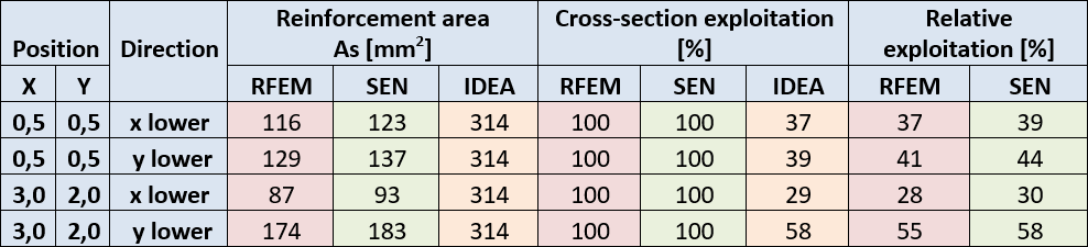
De tabel toont een goede overeenkomst in benuttingsgraad voor alle programma's.
Voor de tweede methode werd in IDEA Concrete wapening met ongeveer hetzelfde oppervlak gedefinieerd als de berekende vereiste wapening in RFEM en SEN. Vervolgens werd de benuttingsgraad van de doorsnede vergeleken. De resultaten worden weergegeven in de volgende tabel:
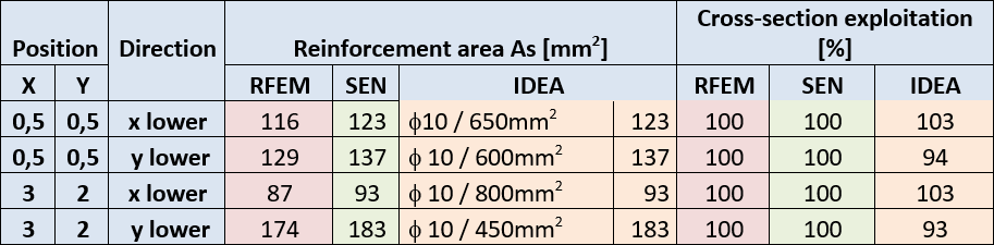
Ook hier is de overeenkomst van de resultaten goed.
Bruikbaarheidsgrenstoestand
Spanningsbegrenzing
De normtoetsing van spanningsbegrenzing verschilt niet van de normtoetsingen voor 1D-elementen.
Scheurwijdtetoets
Aanvullend toetsen 1D-elementen de richting van de scheur die kan worden weergegeven voor 2D-elementen.
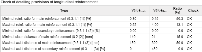
Constructieve bepalingen
De normtoetsing van constructieve bepalingen voor 2D-elementen kan worden opgesplitst in twee basisgroepen:
- Waperingspercentagetoets
- Staafafstandstoets
De normtoetsing van constructieve bepalingen is ook afhankelijk van het type 2D-element. Voor schaal-plaat- en plaatelementen worden afzonderlijke normtoetsingen uitgevoerd voor de hoofdwapening en de verdelingswapening. Voor wandelementen wordt onderscheid gemaakt tussen verticale en horizontale wapening.
De waperingspercentagetoets wordt uitgevoerd in de richting van de hoofdspanningen. De wapening gedefinieerd in de snede van het 2D-element (met uitzondering van de verdelingswapening) wordt getransformeerd naar de richtingen van de hoofdspanningen.
De staafafstandstoets wordt uitgevoerd loodrecht op de richting van de gedefinieerde wapening. Deze toets wordt uitgevoerd voor alle gedefinieerde waperingslagen en de grenswaarden zijn afhankelijk van het type getoetst element en het type gedefinieerde wapening.