Geboute flensplaatmomentverbinding – LRFD
Een ligger met dwarsdoorsnede W12\(\times\)40 is verbonden met een kolom met dwarsdoorsnede W10\(\times\)45. De verbinding is ontworpen als een momentverbinding en is uitgevoerd als een geboute flensplaatmomentverbinding. Al het staal is van kwaliteit A36 (fy = 36 ksi, fu = 58 ksi) en de bouten zijn van kwaliteit A307 (fy = 50 ksi, fu = 65 ksi). De lip platen ter plaatse van de liggerflensen hebben een dikte van 5/8'' en de lip platen ter plaatse van het liggerlijf hebben een dikte van 3/8''. De kolom is verstijfd ter plaatse van de lip platen bij de liggerflensen en heeft een dikte van 5/8''. De kolom wordt belast door een druk kracht van 200 kip, de ligger door een buigend moment van 800 kip-in en een dwarskracht van 30 kip.
Geometrie
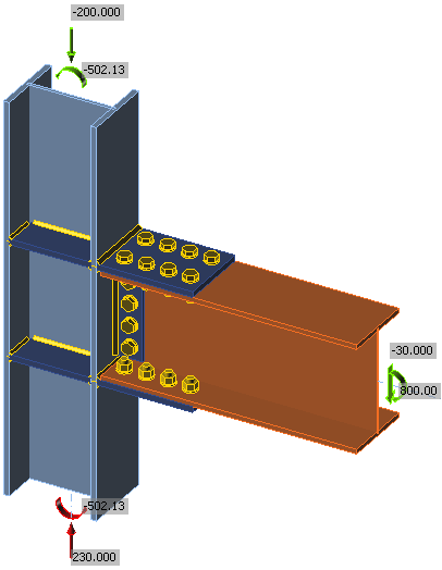
Onderzochte verbinding
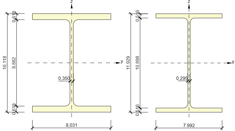
Dwarsdoorsneden van kolom (links) en ligger (rechts)
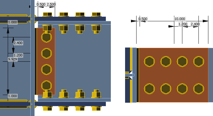
Geometrie van de lip platen
Handmatige beoordeling
De handmatige beoordeling is uitgevoerd conform AISC 360-16. Ter vereenvoudiging wordt aangenomen dat het buigend moment uitsluitend via de flensen wordt overgedragen en de dwarskracht uitsluitend via het lijf. De dwarskracht wordt verondersteld aan te grijpen op het vlak van de kolom. De volgende normtoetsingen zijn vereist:
- Boutsterkte op afschuiving – J3.6
- Druksterkte en scheursterkte bij boutgaten – J3.10
- Blokafschuivingssterkte – J4.3
- Trek sterkte van verbonden elementen – J4.1
- Afschuivingssterkte van verbonden elementen – J4.2
- Lassterkte – J2.4
Het ontwerp van de ligger en de kolom wordt verondersteld elders te worden gecontroleerd.
Krachtverdeling
Het buigend moment wordt overgedragen via bouten op de liggerflens. De afstand tussen de afschuivingsvlakken bedraagt 11,929''. De kracht die aangrijpt op de boutgroep ter plaatse van de flensen bedraagt 67,06 kip.
Het buigend moment wordt verder overgedragen via lassen die de lip platen verbinden met de kolomflens. De afstand tussen de zwaartepunten van de lassen wordt vergroot met de dikte van de lip plaat, d.w.z. 11,929 + 5/8 = 12,554''. De lassen worden belast door een kracht van 63,72 kip.
De bouten ter plaatse van het lijf worden belast door de dwarskracht van 30 kip en door een kleine dwarskracht als gevolg van het buigend moment veroorzaakt door de excentriciteit van de veronderstelde dwarskracht die aangrijpt op het kolomvlak, 1,75''. Deze dwarskracht wordt hier verwaarloosd omdat de benuttingsgraad van de bouten ter plaatse van het liggerlijf naar verwachting niet erg hoog zal zijn en er voldoende reserve aanwezig is.
De lassen ter plaatse van de lip plaat die het liggerlijf verbindt, worden belast door een dwarskracht van 30 kip.
Boutcontrole
Bouten ter plaatse van de liggerflens:
De dwarskracht van 67,06 kip wordt verondersteld gelijkmatig verdeeld te zijn over 8 bouten 3/4'' A307.
Afschuivingssterkte:
\[\phi R_n = \phi F_{nv} A_b = 0.75 \cdot 27 \cdot 0.442 = 8.938 \,\textrm{kip}\]
Druksterkte:
\[\phi R_n = \phi 2.4 d t F_u = 0.75 \cdot 2.4 \cdot 0.75 \cdot 0.516 \cdot 58 = 40.394 \,\textrm{kip}\]
Scheursterkte bij boutgat:
\[\phi R_n = \phi 1.2 l_c t F_u = 0.75 \cdot 1.2 \cdot (1.4-0.406) \cdot 0.516 \cdot 58 = 26.77 \,\textrm{kip}\]
De afschuivingssterkte van één bout bedraagt 8,938 kip, d.w.z. de sterkte van een groep van 8 bouten bedraagt 67,184 kip. De sterkte is voldoende om de dwarskracht van 67,06 kip over te dragen.
Blokafschuivingssterkte:
\[\phi R_n =\phi (0.6 F_u A_{nv} + U_{bs} F_u A_{nt}) \le \phi (0.6 F_y A_{gv} + U_{bs} F_u A_{nt})\]
\[\phi R_n = 0.75 \cdot (0.6 \cdot 58 \cdot 2.97 + 1 \cdot 58 \cdot 0.82) \le 0.75 \cdot (0.6 \cdot 36 \cdot 4.44 + 1 \cdot 58 \cdot 0.82) = 143 \, \textrm{kip}\]
Dit voorbeeld toont de blokafschuivingssterkte van de bovenflens van de ligger. Het verwachte bezwijken wordt verondersteld zich uit te strekken over 4 bouten naast het liggerlijf. Derhalve moet de helft van de belasting die aangrijpt op de boutgroep worden weerstaan, d.w.z. 30,03 kip. De reserve is zeer groot.
Trek vloeiing van de lip plaat:
\[\phi R_n =\phi F_y A_g = 0.9 \cdot 36 \cdot 5.00 = 162 \, \textrm{kip}\]
Trek breuk van de lip plaat:
\[\phi R_n =\phi F_u A_n = 0.75 \cdot 58 \cdot 3.98 = 173 \, \textrm{kip}\]
De plaat heeft een benuttingsgraad van 41 %.
Bouten ter plaatse van het liggerlijf:
De dwarskracht van 30 kip wordt verondersteld gelijkmatig verdeeld te zijn over 4 bouten 3/4'' A307.
Afschuivingssterkte:
\[\phi R_n = \phi F_{nv} A_b = 0.75 \cdot 27 \cdot 0.442 = 8.938 \,\textrm{kip}\]
Druksterkte:
\[\phi R_n = \phi 2.4 d t F_u = 0.75 \cdot 2.4 \cdot 0.75 \cdot 0.295 \cdot 58 = 23.1 \,\textrm{kip}\]
Scheursterkte bij boutgat:
\[\phi R_n = \phi 1.2 l_c t F_u = 0.75 \cdot 1.2 \cdot (1.365-0,406) \cdot 0.375 \cdot 58 = 17.81 \,\textrm{kip}\]
De afschuivingssterkte van één bout bedraagt 8,938 kip, d.w.z. de sterkte van een groep van 4 bouten bedraagt 39 kip. De sterkte is voldoende om de dwarskracht van 30 kip over te dragen.
Afschuivingsvloeiing van de lip plaat:
\[\phi R_n = \phi 0.6 F_y A_{gv} = 1 \cdot 0.6 \cdot 36 \cdot 3.72 = 80 \,\textrm{kip}\]
Afschuivingsbreuk van de lip plaat:
\[\phi R_n = \phi 0.6 F_u A_{nv} = 0.75 \cdot 0.6 \cdot 58 \cdot 2.50 = 65 \,\textrm{kip}\]
De afschuivingssterkte van de lip plaat, d.w.z. 65 kip, is voldoende om de dwarskrachtbelasting van 30 kip over te dragen.
Lascontrole
Lassen nabij de liggerflens:
Lassen die de lip plaat ter plaatse van de liggerflensen verbinden met de kolomflens, moeten 63,72 kip overdragen. De lassen worden belast onder een hoek van \(90^\circ\). Laselektrode E70XX wordt gebruikt met een lasgrootte van 3/8''.
\[F_{nw} = 0.6 F_{EXX} (1+0.5 \sin^{1.5} \theta) = 0.6 \cdot 70 \cdot (1+0.5 \sin^{1.5} 90^\circ) = 63 \,\textrm{ksi}\]
\[\phi R_n = \phi F_{nw} A_{we} = 0.75 \cdot 63 \cdot 4.213 = 199 \,\textrm{kip}\]
De lassterkte is voldoende.
Lassen nabij het liggerlijf:
Lassen die de lip plaat ter plaatse van het liggerlijf verbinden met de kolomflens, moeten 30 kip overdragen. De lassen worden belast onder een hoek van \(0^\circ\). Laselektrode E70XX wordt gebruikt met een lasgrootte van 5/16''.
\[F_{nw} = 0.6 F_{EXX} (1+0.5 \sin^{1.5} \theta) = 0.6 \cdot 70 \cdot (1+0.5 \sin^{1.5} 0^\circ) = 42 \,\textrm{ksi}\]
\[\phi R_n = \phi F_{nw} A_{we} = 0.75 \cdot 42 \cdot 4.374 = 138 \,\textrm{kip}\]
De lassterkte is voldoende.
Controle in IDEA StatiCa
De platen worden gecontroleerd door middel van eindige elementenanalyse. Het bilineaire materiaalmodel wordt gebruikt met de vloeigrens vermenigvuldigd met de staalweerstandsfactor \(\phi = 0.9\). De krachten die aangrijpen op de overige componenten van de verbinding, d.w.z. bouten en lassen, worden eveneens bepaald door middel van eindige elementenanalyse, maar hun sterkte wordt gecontroleerd aan de hand van standaardformules uit AISC 360-16. Het meest belaste laselement wordt gecontroleerd en bij verdere belasting verspreidt de spanning in de las zich naar verdere laselementen. Daardoor is de uiteindelijke lassterkte hoger dan eenvoudigweg de kracht te delen door de benuttingsgraad van de las.
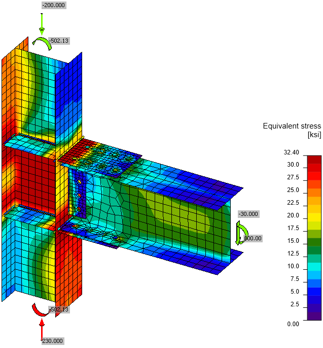
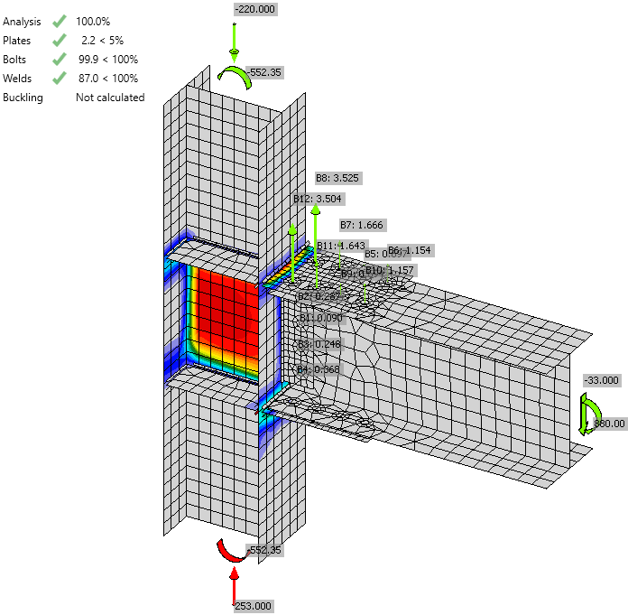
Von Mises spanning
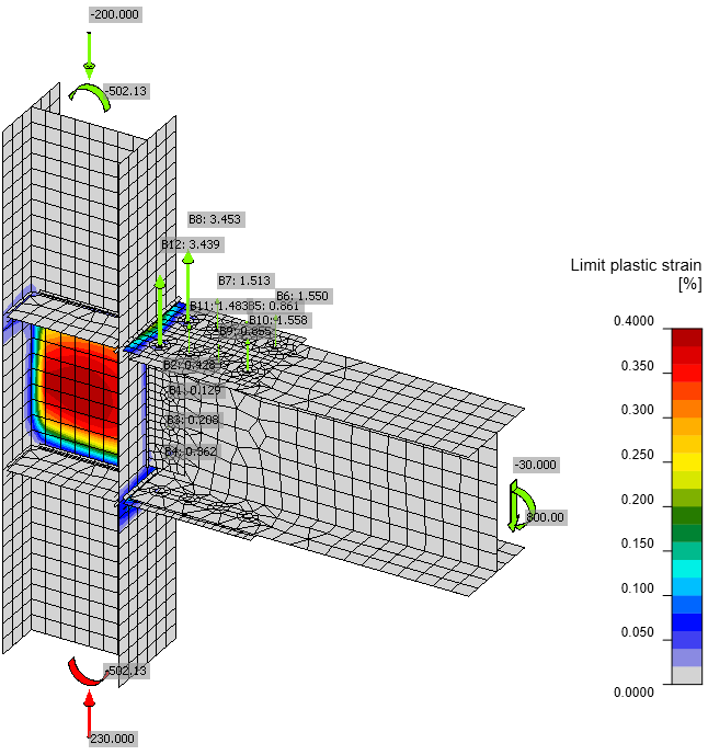
Plastische rek inclusief de trekkrachten in de bouten
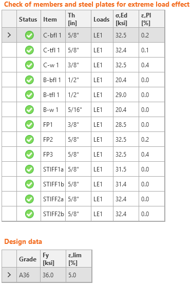
Controle van spanning en rek van platen
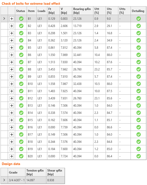
Controle van bouten
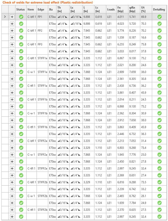
Controle van lassen
Vergelijking
Het is duidelijk dat de eindige elementenanalyse een andere verdeling van inwendige krachten laat zien dan de eenvoudige aannames. De dwarskracht wordt ook gedeeltelijk overgedragen via de lip platen ter plaatse van de liggerflensen, zoals blijkt uit de trekkrachten in de bouten en de hoge spanningen veroorzaakt door buiging van de lip plaat nabij de kolomflens. De individuele sterkten van bouten en lassen komen goed overeen, maar de belastingen en belastingsrichtingen zijn verschillend.
Terwijl de handmatige controle aantoont dat de verbinding volledig benut is vanwege de afschuivingssterkte van de bouten ter plaatse van de liggerflensen, toont IDEA nog enige reserve. De belastingen kunnen met 10 % worden verhoogd om volledige benutting in IDEA te bereiken. Dit is te verwachten vanwege de vereenvoudiging in de krachtverdeling bij de handmatige beoordeling.
De normtoetsing in ontwerpsoftware IDEA StatiCa Connection komt goed overeen met de handmatige beoordeling conform AISC 360.

Toegevoegde downloads
- AISC.pdf (PDF, 1,2 MB)