Reinforcement in Partially Loaded Area
You can design the reinforcement in the partially loaded area in a more effective way since version 20.1. The reinforcing bars are part of the CSFM model, and the bond between concrete and bars is treated as perfect.
About Partially Loaded Area
This feature is suitable mainly for precast and bridge structural engineers who are dealing with significant reactions in the bearings or concentrated prestressed forces from the tendons in the beams. The benefit is hidden beyond non - conservative design, saving material and money.
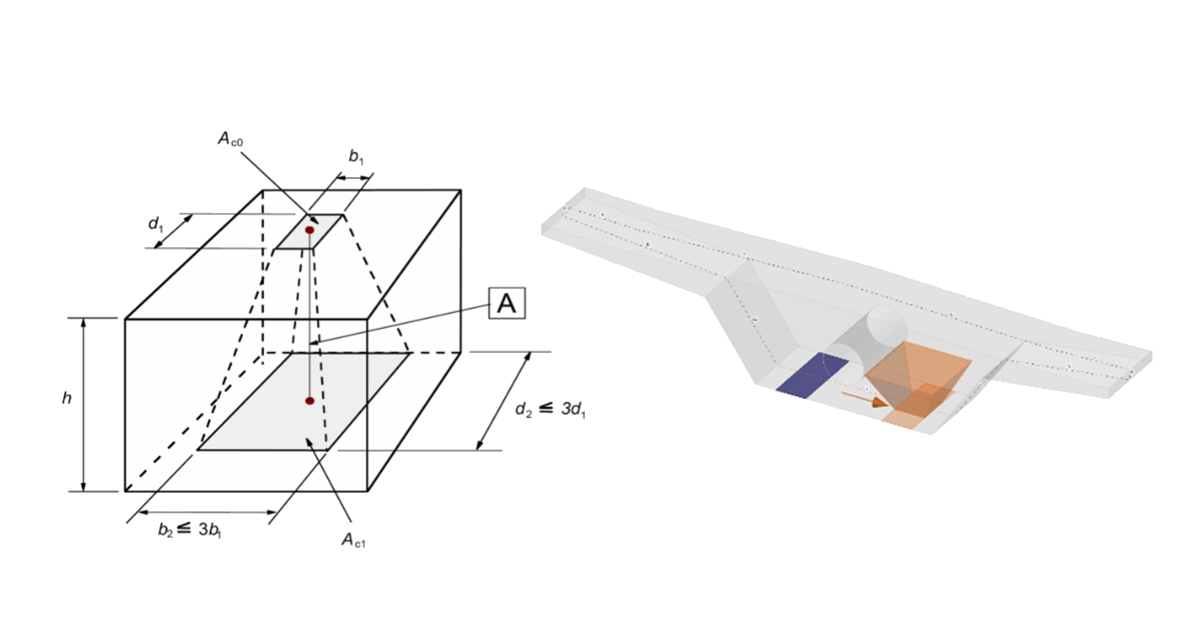
We have figured out how to deal with triaxial stress in partially loaded areas. In these areas crushing of concrete is allowed, and the resistance of concrete in compression can be raised due to transverse confinement according to valid standards (Eurocode). The increase of the resistance can be up to 3 times the cylinder strength of concrete.

The partially loaded area can be found on every structure. Some typical examples are bridge diaphragms with an area above the bearings, areas under the anchor, or concentrated load on the edge of the wall. Partially loaded areas are designed according to the requirements of the Eurocode and simultaneously are restrained by model geometry (openings, thickness, edges, abrupt change of cross-section).

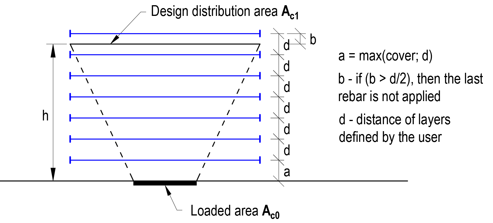
The increase of concrete resistance can be considered if the confinement is kept. Due to this condition, reinforcement bars are automatically added to pass the condition regarding confinement and Eurocode provision.

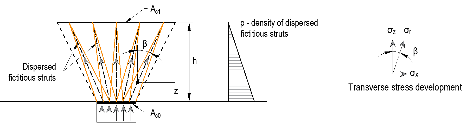
This functionality guarantees that models are getting converge and simultaneously comply with design criteria for valid standards (Eurocode). The implemented method is independent of the finite element mesh. The bearing capacity is increased with the changing of the concrete area. The consequence of this state is constant stress along with the height of a cone. Dispersed fictitious struts affect artificially the stiffness of the cone and correctly redistribute the transverse stress, which appears in this area. The density of each dispersed strut is increased to the direction of the applied load.
Known limitations come out from the standards valid in Eurocode.
- Cones cannot coincide
- The area Ac1 and Ac0 lie on the resultant of the acting force