Terhelések és kombinációk
Terhelések
A tehereseteket ugyanúgy lehet meghatározni, mint a 2D vasbeton elemek esetén. Ez azt jelenti, hogy minden teheresethez vagy Állandó, vagy Változó tehertype rendelhető. Az Állandó tehereseteket először alkalmazzák a modellre, és sikeres számítás után kerülnek alkalmazásra a Változó tehereseteket.
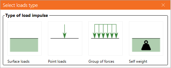
Teherimpulzusok típusai
Összesen 4 típusú teherimpulzus adható hozzá minden teheresethez.
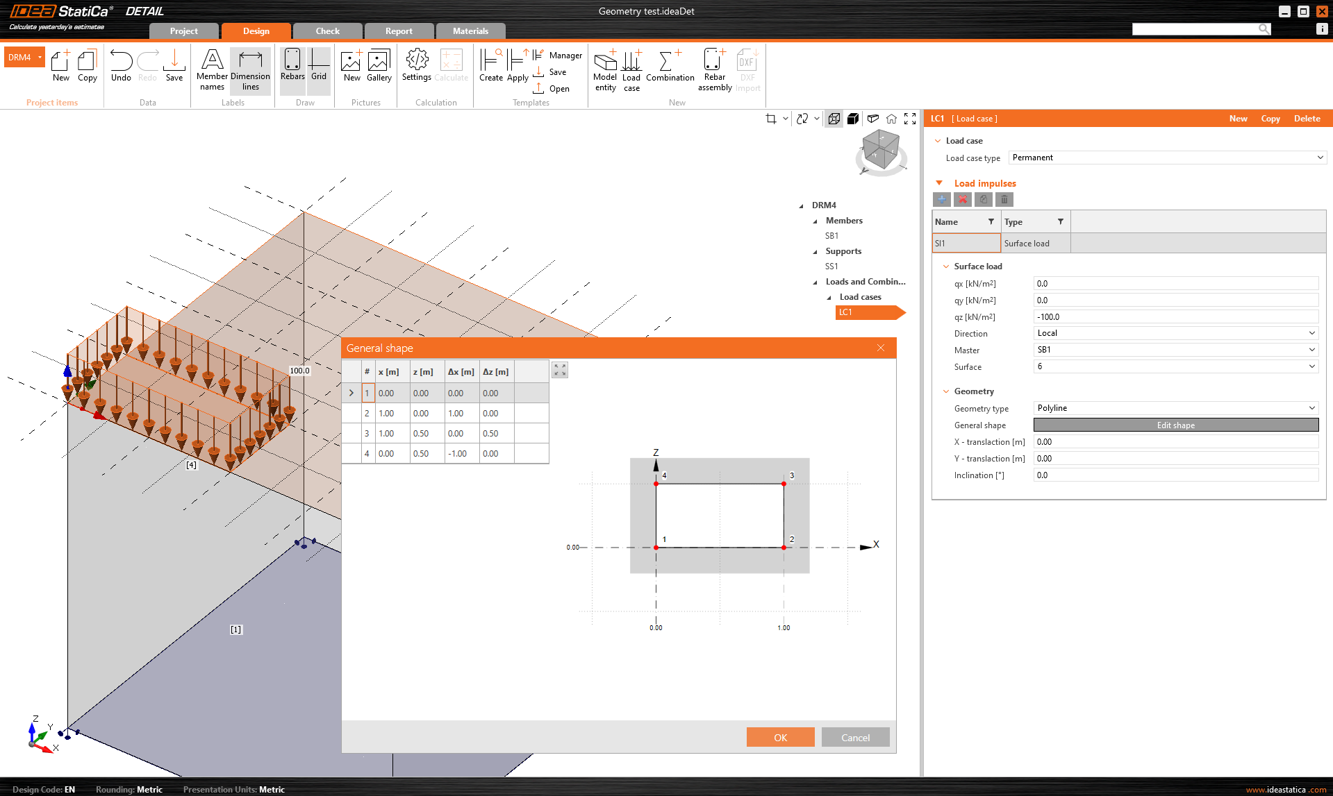
A Felületi terhek meghatározása azonos a Felületi támasz meghatározásával. Ez azt jelenti, hogy kétféleképpen adható meg: Teljes felület és Töröttvonal. Felületi terhek esetén természetesen a teher intenzitása a három általános irányban adható meg.
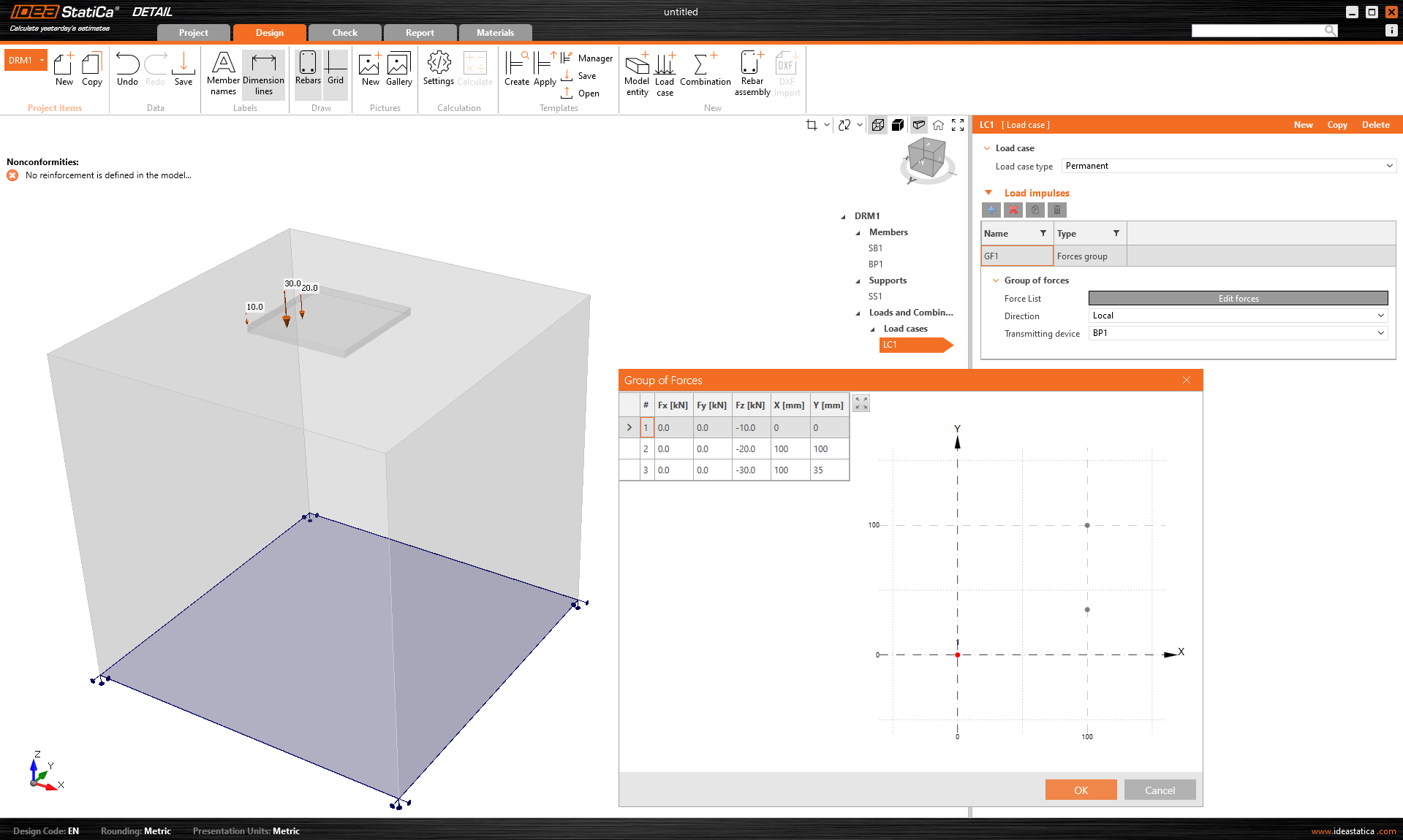
Az Erőcsoport olyan teherelem, amely lehetővé teszi, hogy táblázat segítségével a modell bármely pontján három irányban erőket adjon meg. Hivatkozható a talplemezre vagy a betonblokk felületére. Táblázatos bevitelhez ismét lehetséges a másolás-beillesztés funkció használata a táblázatkezelő programból.
Az önsúlyt minden modellbe be kell számítani. Például a hajlítónyomatékkal terhelt beton alapozások nem dőlnek fel olyan könnyen.
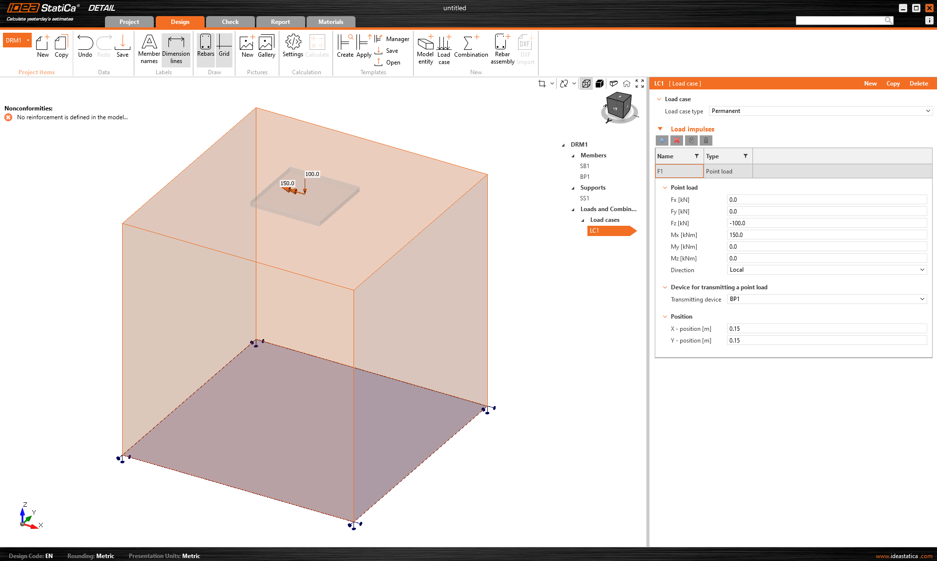
Pontterhek közvetlenül a talplemezre vihetők fel hat belső erővel: Fx, Fy, Fz, Mx, My és Mz általános helyzetben.
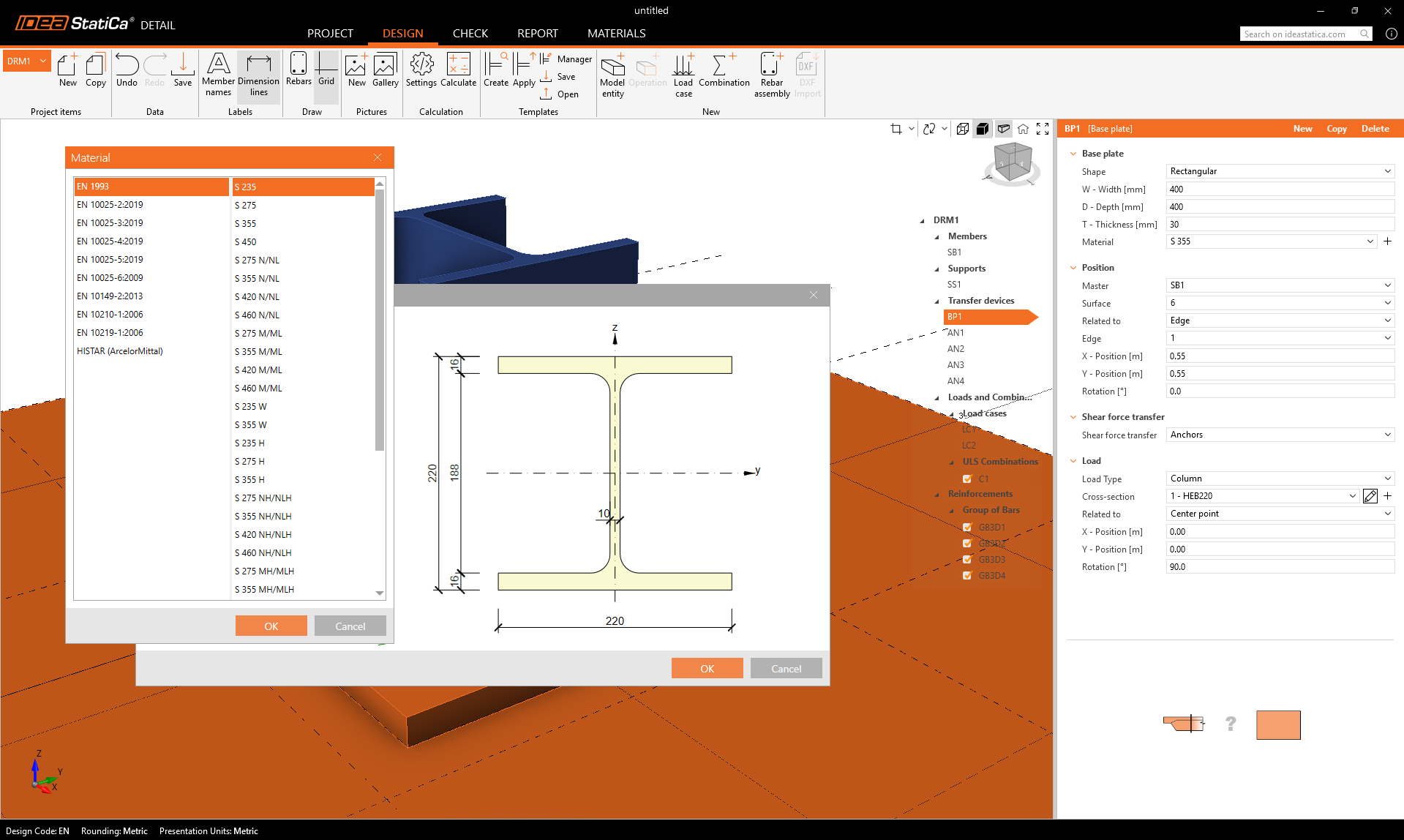
Talplemez alkalmazásakor az erő közvetlen felvitele egy valósághű, deformálható talplemezre nem reális feszültség-újraelosztáshoz vezethet a lemez, a horgonyok és a beton között. Ezért célszerűbb a második lehetőséget – a csonkot – alkalmazni.
A csonk
A csonk az oszlop talplemez feletti rövid részét képviseli, amelyet héjelem-szerkezetként modelleznek, és fizikailag pontos interfészként viselkedik a belső erők és a lemez között. Szabványos szelvényadatbázist használ.
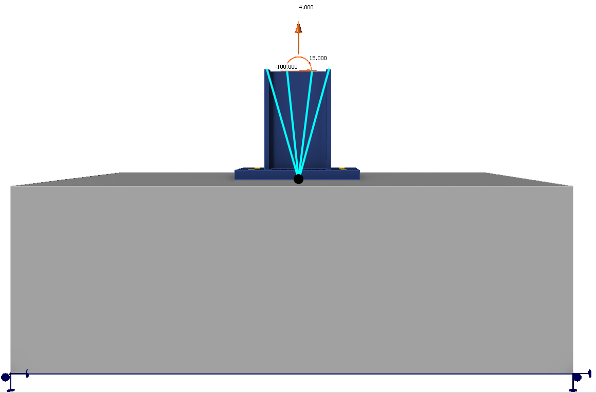
A 6-komponensű belső erőrendszer (erők és nyomatékok) a csonk alsó lapjának – azaz az oszlop talpának – egyetlen pontján kerül felvitelre.
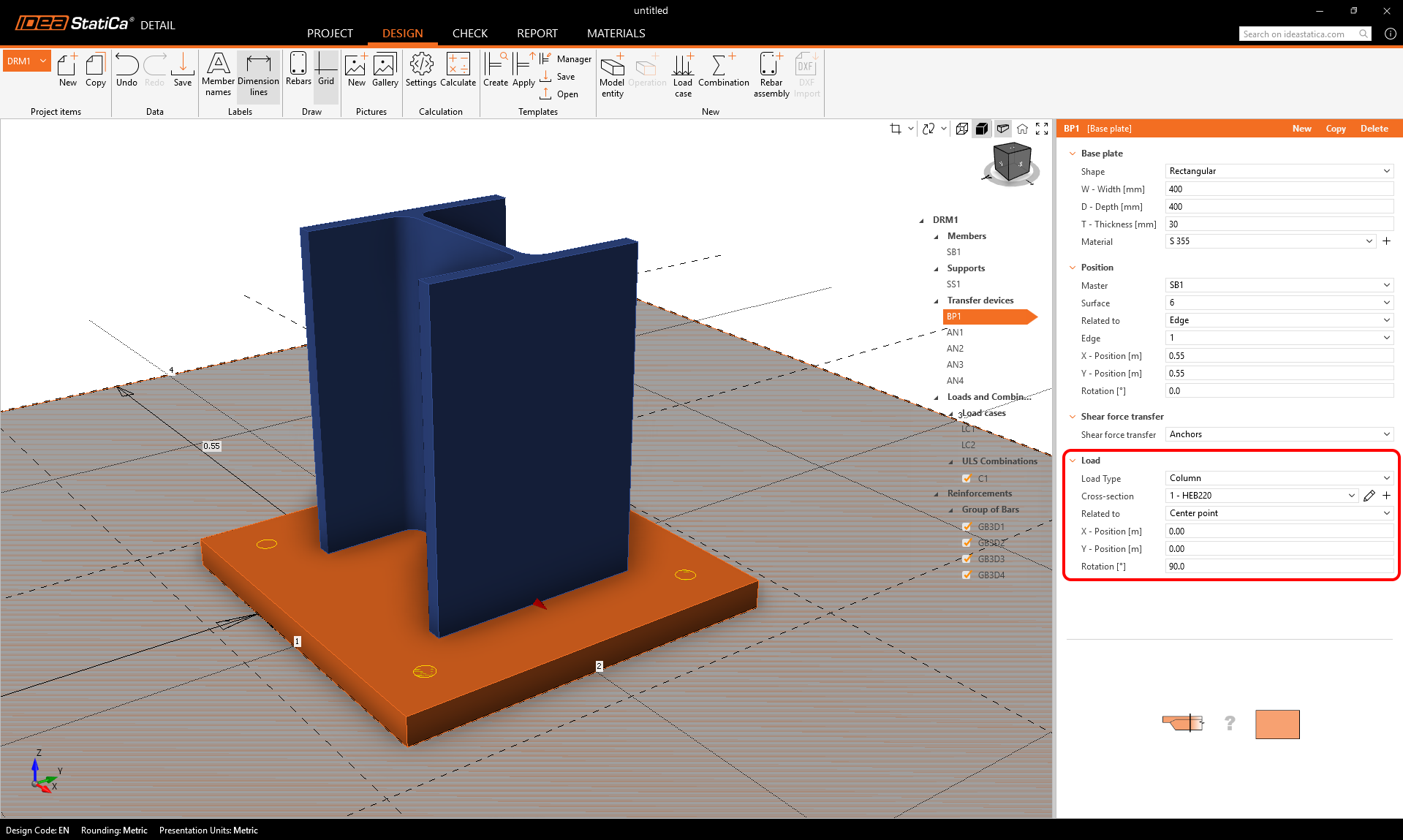
A kényszerfeltételek átviszik az erőket a csonk felső lapjára, ahonnan azok természetes módon a csonkon keresztül újraelosztódnak a talplemezbe, a horgonyokba és a betonba.
Ez a megközelítés megőrzi az oszlop és a lemez közötti valósághű merevségi kölcsönhatást, és kiküszöböli a manuális újraelosztás vagy mesterséges feltételezések szükségességét.
A csonk az IDEA StatiCa 25.1-es verziójában jelent meg.
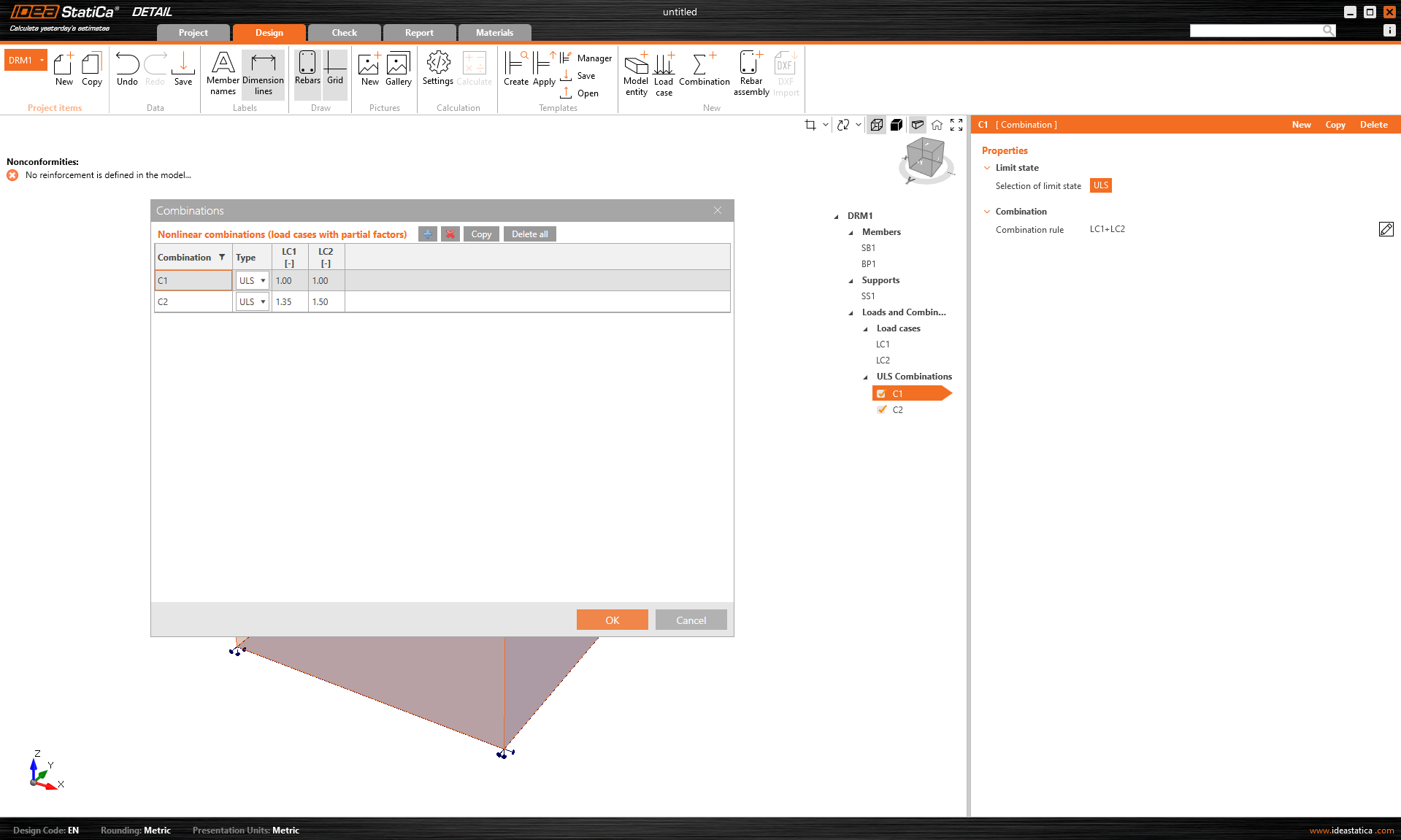
Kombinációk
Mivel az IDEA StatiCa Detail számítása nemlineáris, úgynevezett nemlineáris kombinációkat alkalmaznak. Ez azt jelenti, hogy az egyes tehereseteket nem számítják ki külön, majd az eredményeket nem adják össze. Éppen ellenkezőleg, az azonos tehertípusú tehereseteket a számítás előtt összegzik – természetesen a kombinációkban meghatározott megfelelő szorzókkal –, majd az egyes kombinációkat számítják ki. Ezért a számítás megkezdésének előfeltétele legalább egy kombináció megléte.
Csak ULS kombinációk határozhatók meg.