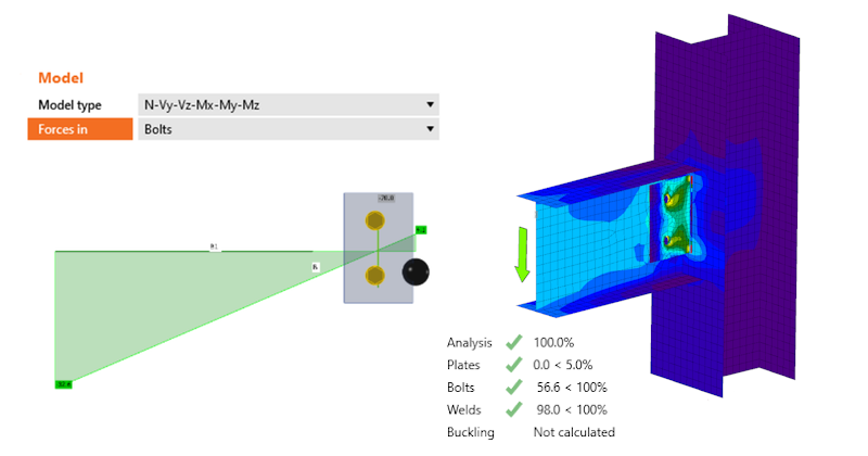
Hogyan kell meghatározni a helyes terhelési pozíciót (Forces in)
Valódi csukló vs. elméleti csukló
Annak biztosítása érdekében, hogy a számítási modell összhangban legyen a kapcsolat tényleges alakjával és statikai viselkedésével, figyelembe kell vennünk a hajlítónyomaték alakját és a nyíróerő helyzetét a kapcsolatban. Egy egyszerű példán – egy oszlophoz csatlakozó vízszintes gerenda – mutatjuk be a nyomatéki és csuklós kapcsolatok modellezésének különbségeit.
Nyomatéki kapcsolat
Ez a nyomatéki kapcsolat sematikus „valódi" alakja (bal oldal) és az analízishez használt szerkezeti modellje (jobb oldal).
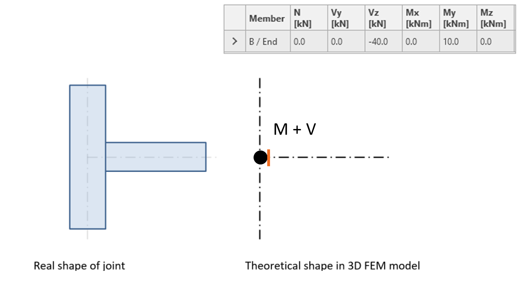
Az IDEA StatiCa Connection Teherhatások fülén meghatározzuk azokat az erőket, amelyekkel a kapcsolat minden egyes eleme hat a csomópontra (általában a kapcsolat középpontjára, az elemtengelyek metszéspontjára). A fenti ábra táblázata szintén mutatja azokat az erőket, amelyekkel a vízszintes B elem hat az oszlopra. A vízszintes elemen ható belső erők diagramjai a következők.
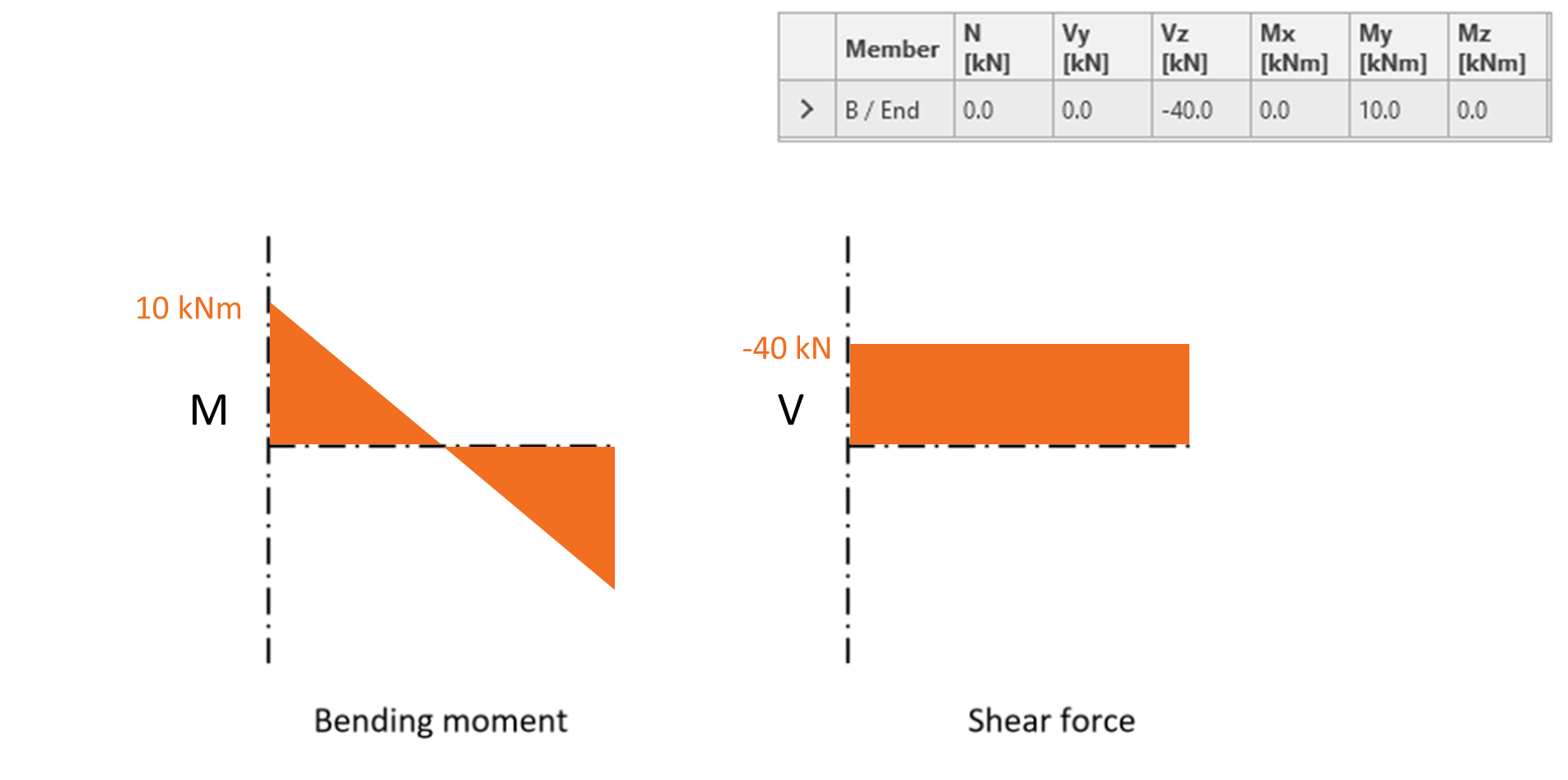
Az IDEA StatiCa Connection-ben az elemek mentén ható hajlítónyomatékok lineárisként vannak egyszerűsítve. A csatlakoztatott elem kezdeténél a megadott hajlítónyomaték kerül alkalmazásra, és a nyomaték a csomóponttól távolodva lineáris függvényként változik, amelynek meredekségét a megadott nyíróerő határozza meg.
Tekintse meg a hajlítónyomaték-eloszlást és egyéb fontos információkat tárgyaló videót.
Csuklós kapcsolat
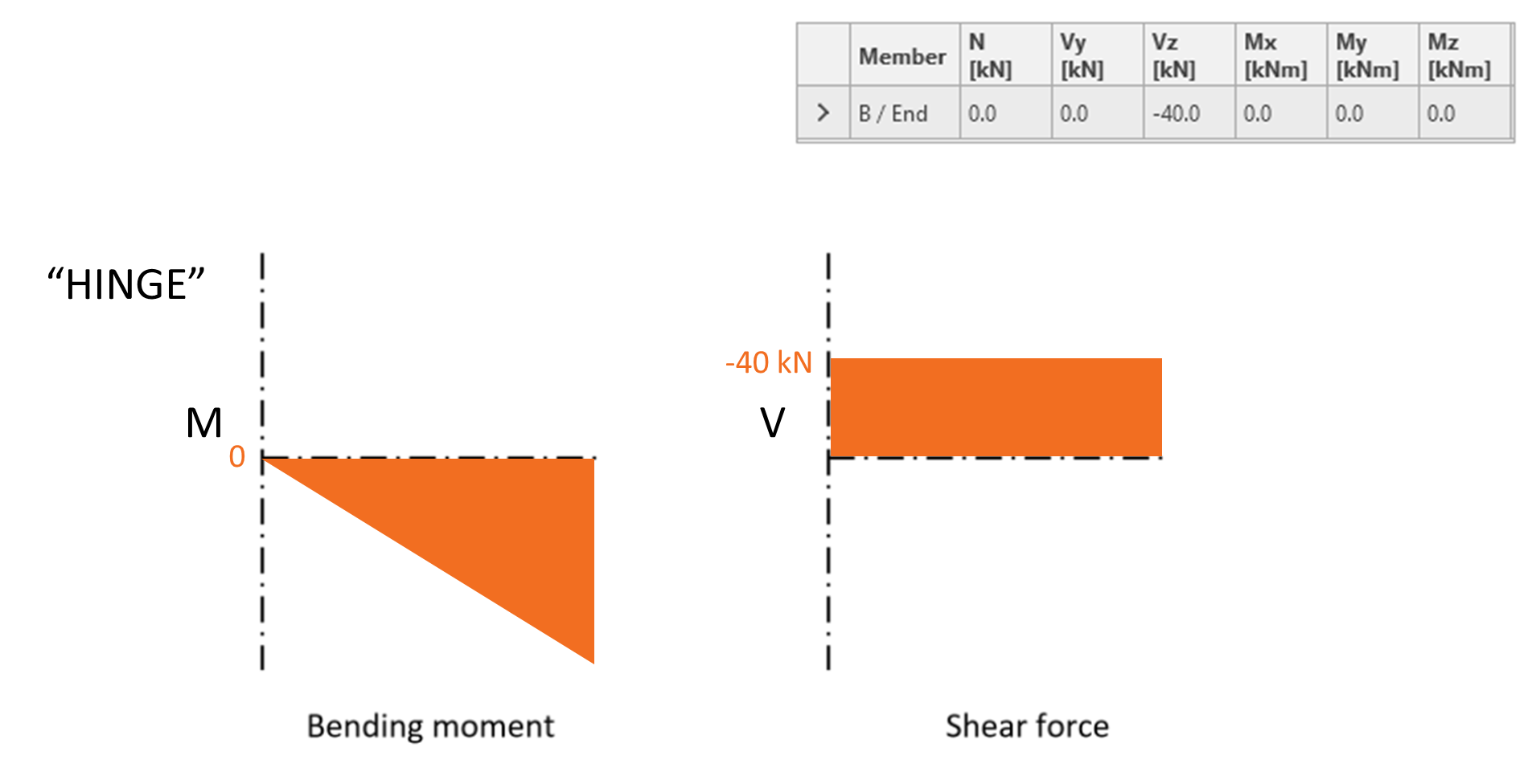
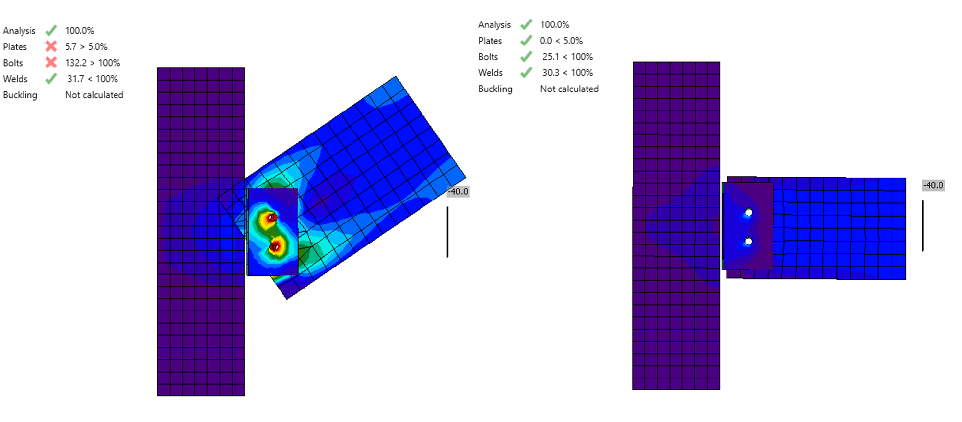
Csuklós kapcsolat esetén a kapcsolatban a hajlítónyomaték nulla. A csuklósan csatlakoztatott vízszintes elem hajlítónyomaték- és nyíróerő-diagramjai a következő ábrán láthatók. Vz= -40 kN nyíróerőt és nulla My hajlítónyomatékot kell megadni a Connection alkalmazásban a megfelelő belső erők előidézéséhez. Ebben az esetben azt mondjuk, hogy a nyíróerő pozíciója (és ezáltal a nulla hajlítónyomaték helye) a csomópontban van (a kapcsolat középpontjában).
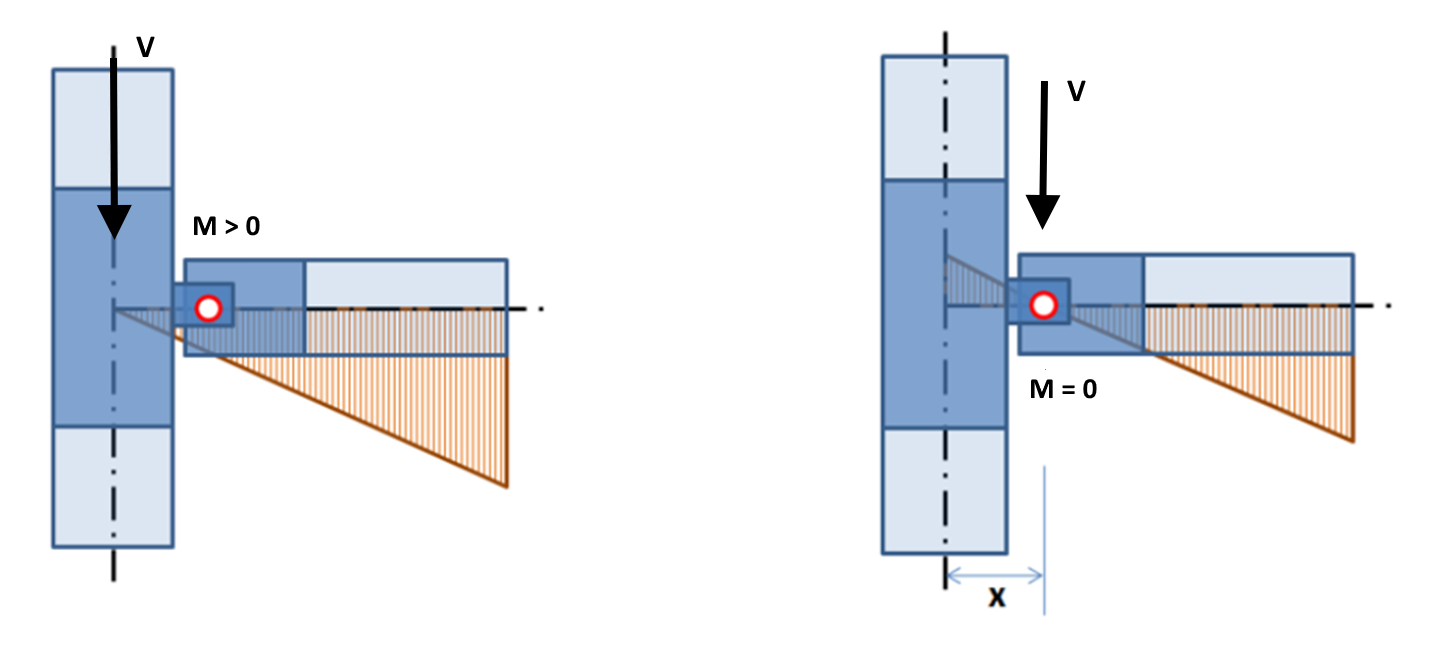
A fenti ábra az elméleti helyzetnek felel meg, ahol a csukló helye közvetlenül a csomópontban van (a kapcsolat középpontjában). Így modellezik általában a csuklós kapcsolatot a globális analízis modellben. Azonban egy valódi szerkezetben az elfordulás pontja (csukló) el van tolva a csomópont középpontjától. Vegyük például egy függőleges hevederlemezzel ellátott csavaros gerenda-oszlop nyírókapcsolatot, ahol a csukló a csavarcsoport súlypontjában feltételezhető.
Ahogy a következő ábrán látható, ha a csukló tényleges helyzetét nem veszik figyelembe a modellben, nem nulla hajlítónyomaték keletkezik a valódi csukló helyén (az ábra bal oldala). Ez nyilvánvaló hiba. Ennek elkerülése érdekében a nyíróerő pozícióját (és ezáltal a nulla hajlítónyomaték helyét) a csatlakoztatott elemben kell módosítani (jobb oldal).
Az erők pozíciójának beállítása
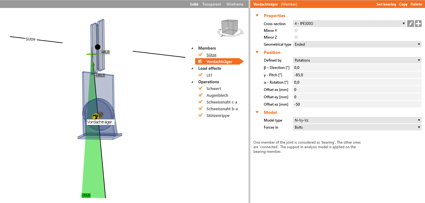
Az alkalmazásban a nyíróerő pozíciója az adott szerkezeti elem Modell szakaszában határozható meg. A két eset közötti különbség itt látható:
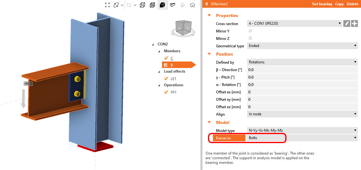
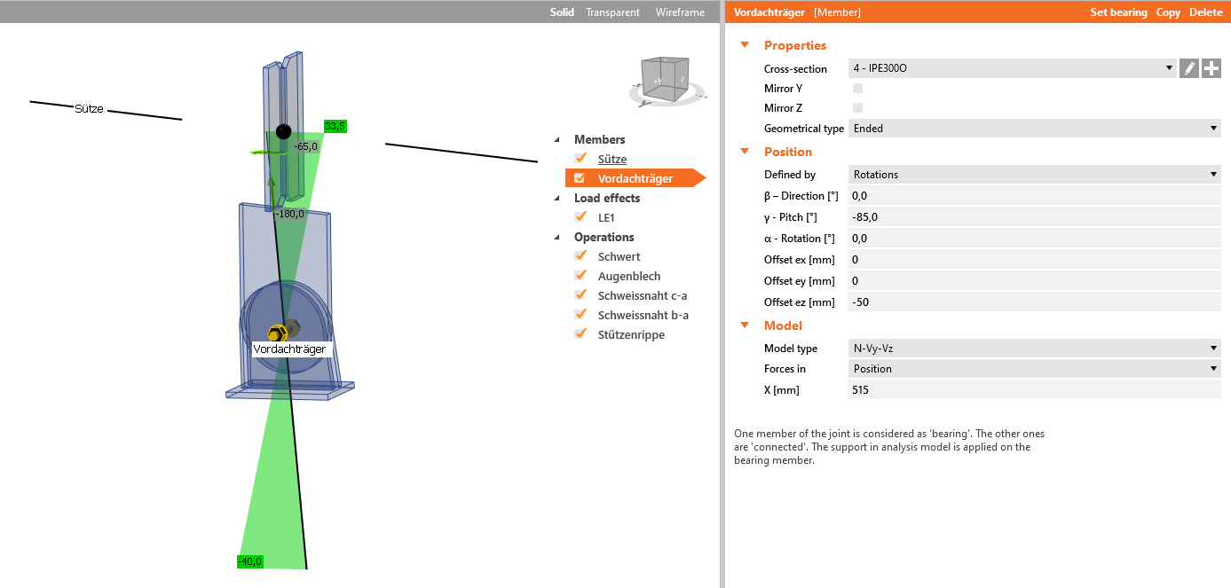
Bal: Forces in Node Jobb: Forces in Bolts
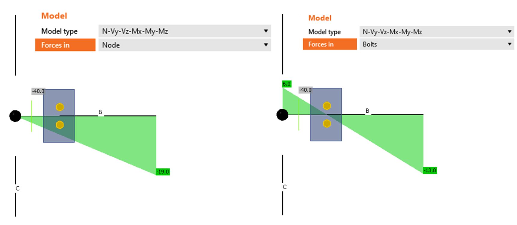
A bal oldali helyzetben hajlítónyomaték keletkezik a csukló pontjában, amely felfelé forgatja az elemet. Ez a nyomaték (amely a csomóponttól lineárisan növekvő nyíróerőből ered) helytelen viselkedést idéz elő a vízszintes elemben.
A beállítást könnyen javíthatjuk a nyíróerő áthelyezésével a csukló pozíciójába. Ebben az esetben (jobb oldali kép) a vízszintes gerenda a vártnaknak megfelelően hajlik.
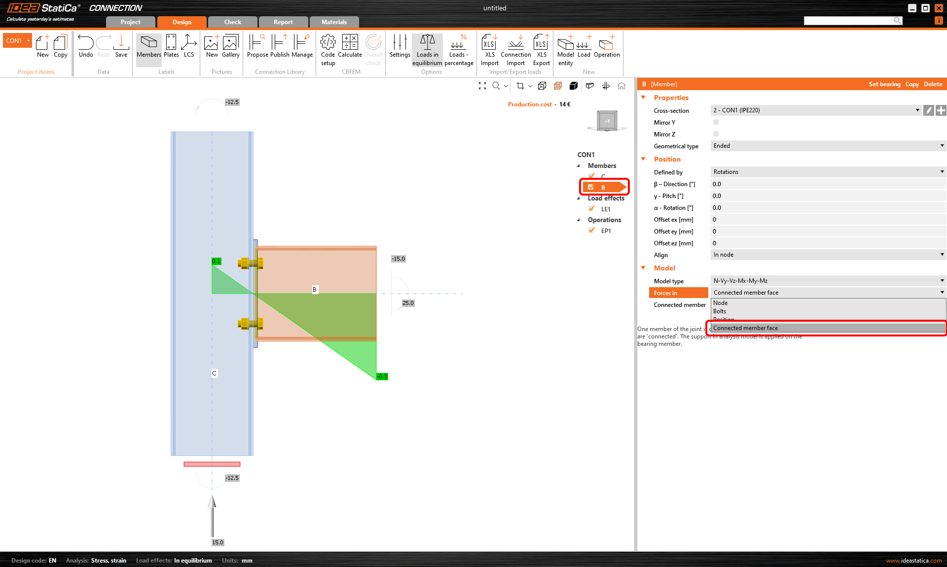
A harmadik lehetőség a Forces in Position. Egyes műveleteknél, különösen akkor, amikor egy kapcsolatot alapvetőbb műveletek összeállításaként hoznak létre (pl. merevítő lemez, vágás, csavarhálózat), a Forces in Bolts funkciónak nincs hatása, és a nulla hajlítónyomaték nem tolódik el a feltételezett csukló helyére.
Ezért a Forces in Position módszert kell választani, és meg kell adni a megfelelő X távolságot.
A 23.1-es verziótól kezdve hozzáadtuk a nyíróerő pozíciójának meghatározási lehetőségét az elem felületénél. A vonatkozó cikk elolvasásával megismerheti a nyíróerő-pozíció megadását és megjelenítését.
A csuklós kapcsolatokat gyakran nyírási kapcsolatoknak is nevezik. Hangsúlyozni kell, hogy a nyíróerő pozíciója eltérhet az egyes nyírási kapcsolattípusoknál, és nem feltételezhető általánosan, hogy a nulla hajlítónyomaték a csavarcsoport súlypontjában van. A Amikor a nyírási kapcsolat hajlítónyomatékot ad át című cikk részletesebben tárgyalja az egyes nyírási kapcsolattípusok közötti különbségeket.
Webinárium felvétel
Tekintse meg korábbi webináriumi felvételeinket, amelyekben a nyíróerő pozícióját tárgyaljuk.
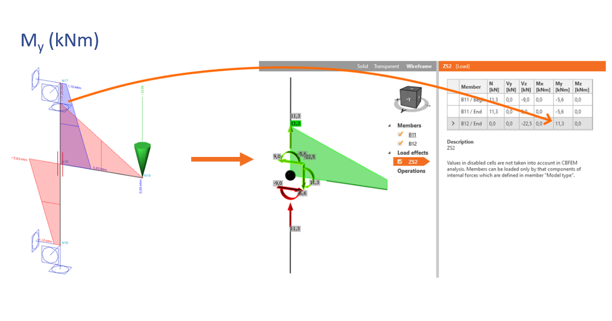
A szerkezeti modellből kapott csomóponti belső erők pozíciója az excentricitások miatt eltolódhat az origótól. Ez a hatás alulbecsüli a kapcsolatban ható belső erőket. Nézzük meg, hogyan lehet közvetlenül a műveletben megváltoztatni a belső erők pozícióját, és elkerülni a helytelen eredményeket.
Próbálja ki az IDEA StatiCa legújabb verzióját még ma
Csatolt letöltések
- How to define correct load position (Forces in) (1).ideaCon (IDEACON, 38 kB)