Base Plate Connections (AISC)
Mark D. Denavit and Kayla Truman-Jarrell prepared this verification example in a joint project of The University of Tennessee and IDEA StatiCa.
1 Description
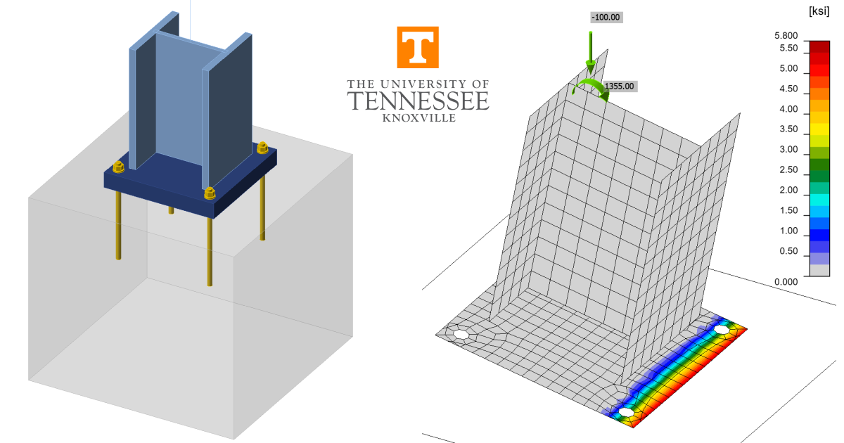
A comparison between results from the component-based finite element method (CBFEM) and traditional calculation methods used in US practice for base plate connections is presented in this article. Three loading conditions are evaluated: concentric axial compressive load, shear load, and combined axial compressive load and moment. A schematic of the column-to-base plate connection investigated is shown in Fig. 1.
The traditional calculation methods are based upon the recommendations presented in AISC Design Guide 1 (Fisher and Kloiber 2006). The recommendations presented in this guide are based on simplifying assumptions of the behavior of the base plate that can lead to highly conservative results if redistribution of bearing stress is possible after base plate yielding or unconservative results if the tensile forces in the anchor rods are underestimated. In particular, the assumption of uniformly distributed bearing stress (i.e., rigid base plate) is often inaccurate since the flexibility of the base plate results in a non-uniform stress distribution (Fitz et al. 2018). Accordingly, results from traditional calculations based on alternative assumptions that are less conservative will also be presented. In both cases, the calculations were performed in accordance with the provisions for load and resistance factor design (LRFD) in the AISC Specification (2016). The ACI Code (2019) also includes provisions relevant to the strength of base plate connections. However, concrete limit states other than concrete bearing strength were avoided in this study and the provisions for concrete bearing strength in the ACI Code are identical to those in the AISC Specification.
The CBFEM results were obtained from IDEA StatiCa Version 22.1. The maximum permitted loads were determined iteratively by adjusting the applied load input to a value that the program deems safe but if increased by a small amount (e.g., 1 kip) the program would deem unsafe. Joint design resistance analysis type can help identify maximum permitted loads. However, some approximation is made in the evaluation of the joint design resistance, therefore all results in this report are based on Stress-Strain analysis type.
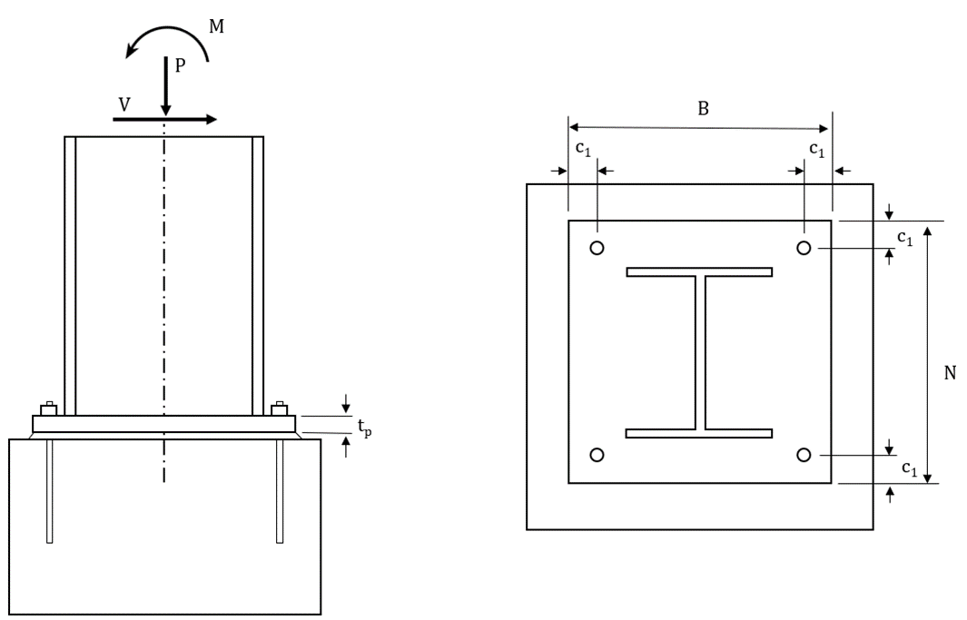
Fig. 1 Schematic of base plate connection showing wide flange column. Base plate for the HSS column is similar
2 Concentric Axial Compressive Load
First, base plates subjected to concentric axial compressive load are investigated. Limit states evaluated for this loading condition are concrete crushing and flexural yielding of the base plate. Two cases are examined, one with a rectangular HSS column and one with a wide flange column.
For the case with the rectangular HSS column, the column section was a HSS10x4x5/8 (ASTM A500 Gr. C, Fy = 50 ksi) and the plate was square with plan dimensions of 12 in. by 12 in., thickness varying from 0.25 in. to 2.50 in., and steel conforming to ASTM A36 (Fy = 36 ksi). Anchor rods were 3/4 in. diameter (ASTM F1554 Gr. 36, Fy = 36 ksi) and had an edge distance of c1 = 1 in. The holes for the anchor rods were 1-5/16 in. in diameter in accordance with the recommendations of Table 14-2 of the AISC Manual (2017). The base plate was assumed to bear directly on the concrete (f'c= 4 ksi). The plan area of the concrete was large such that the maximum permitted bearing strength would apply (i.e., \(\sqrt{A_2/A_1} \ge 2\)). A three-dimensional view of the base plate connection is shown in Fig. 2.
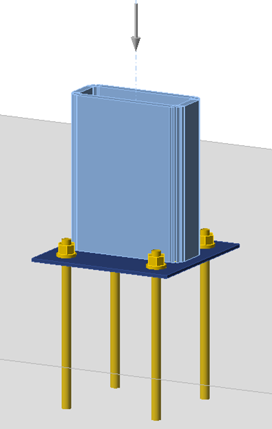
Fig. 2 Three-dimensional view of the base plate with HSS column
The maximum factored axial compressive loads that can safely be applied to the base plate connection as determined from IDEA StatiCa and traditional calculations are presented in Fig. 3. For thick base plates, i.e., tp ≥ 2.25 in., the traditional results and those from IDEA StatiCa are nearly identical. For these cases, bearing controls the strength and the whole area of the base plate is in contact with the concrete. The small difference in strength between results of the traditional method and IDEA StatiCa is because IDEA StatiCa considers the holes for the anchor rods when computing the bearing area while the reduction in area due to the holes is typically neglected in the traditional method.
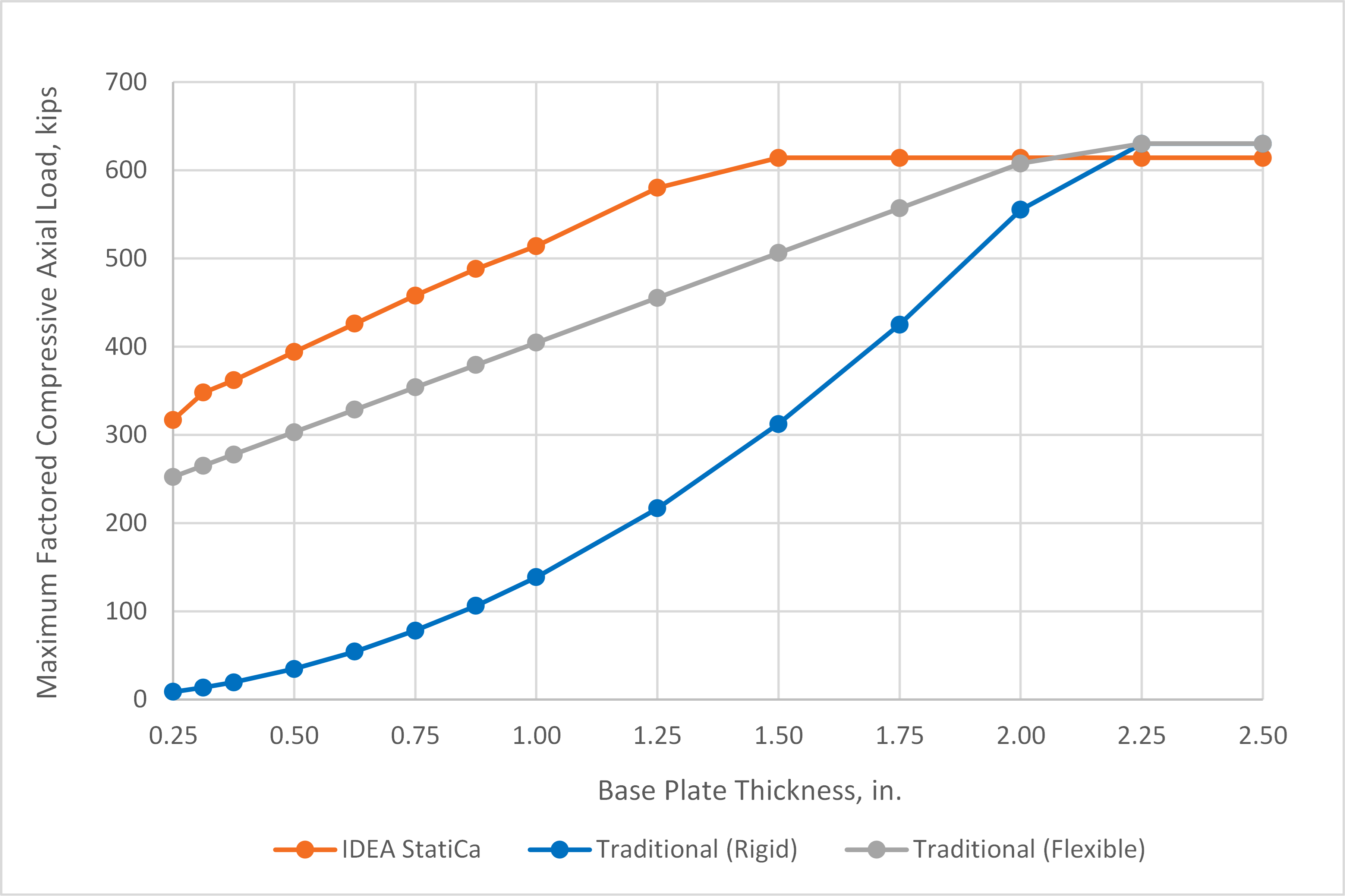
Fig. 3 Maximum factored compressive axial load vs. plate thickness for base plate with HSS column
For thinner base plates, results from the traditional calculations and IDEA StatiCa differ significantly. For these cases, the traditional calculations are controlled by base plate bending while the controlling limit state in IDEA StatiCa is concrete crushing. The uniformly distributed bearing stress assumed in AISC Design Guide 1 results in large flexural demands in the base plate. However, the base plate, especially when thin, is flexible and will deform resulting in a distribution of bearing stresses concentrated below the column as shown in Fig. 4. Yielding of the base plate further increases the flexibility of the base plate and limits the bearing stress at the extremities of the base plate. This behavior is modeled explicitly in IDEA StatiCa. Thus, while yielding of the base plate occurs, the plastic strain in the base plate never reaches the 5% limit and concrete strength controls.
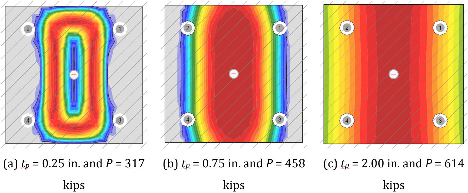
Fig. 4 Bearing stress distribution from IDEA StatiCa for base plate with HSS column. Hatching indicates area A2 and extends beyond the view
To explore the differences further, the traditional calculations were repeated with assumptions more consistent with a flexible base plate. The assumed stress distribution for these alternative traditional calculations is shown in Fig. 5. The bearing stress is uniform, but only over a portion of the base plate. The magnitude of the bearing stress is equal to the maximum permitted by the AISC Specification (2016) (i.e., \(\phi 1.7 f'_c\), noting that the plan area of the concrete is large). The width of the bearing area is dependent on the applied load and bearing stress. For these calculations, the location of the yield lines was the same as recommended in AISC Design Guide 1. While this alternative assumption regarding the distribution of bearing stress is different than that presented in the guide, it still complies with the AISC Specification (2016). Another way of interpreting the alternative bearing stress assumption is that portions of the base plate that are in excess of what is needed for concrete bearing are neglected.
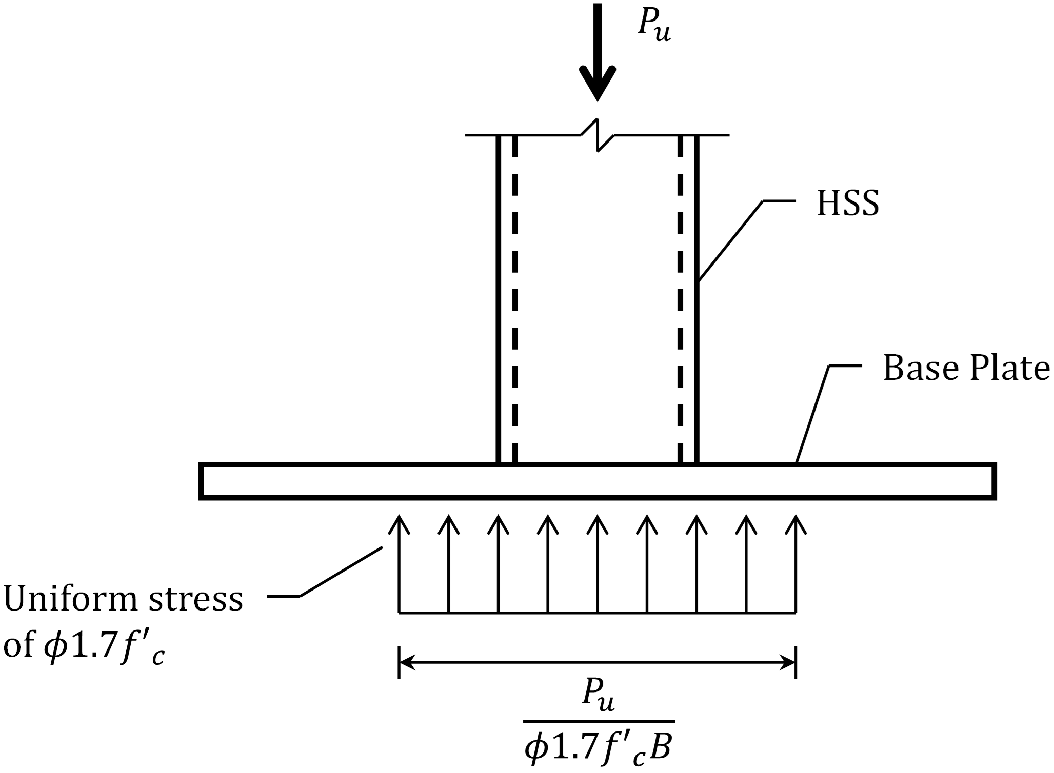
Fig. 5 Assumed bearing stress distribution for the traditional (flexible) calculations for base plate with HSS column
The maximum factored axial compressive loads computed using the alternative traditional calculations are presented in Fig. 3. Use of the alternative bearing stress assumption provides strengths that are much higher than those using the assumptions of AISC Design Guide 1. Given that both sets of assumptions are valid, this indicates that assuming uniform bearing stress over the entire base plate is conservative for base plates that are oversized for bearing. The strengths from IDEA StatiCa are still greater than the strengths from the traditional calculations using the alternative assumption. The reason for this is that the bearing stress distribution in IDEA StatiCa is not uniform (Fig. 4). The stresses are concentrated near the column thus placing less flexural demand on the plate. While this behavior is physically realistic, it is difficult to capture with hand calculations.
The geometry of the HSS base plate connection makes calculation of flexural demands in the base plate with more realistic assumptions of the bearing stress distribution simple. Such calculations are more difficult with wide flange columns, but the uniform bearing stress distribution assumption is similarly conservative. To explore this, additional analyses were performed with a W12x120 (ASTM A992, Fy = 50 ksi) column on a square base plate with plan dimensions of 18 in. by 18 in., thickness varying from 0.25 in. to 3.00 in., and steel conforming to ASTM A36 (Fy = 36 ksi). Anchor rods were 3/4 in. diameter (ASTM F1554 Gr. 36, Fy = 36 ksi) and had an edge distance of c1 = 1.5 in. The holes for the anchor rods were 1-5/16 in. in diameter in accordance with the recommendations of Table 14-2 of the AISC Manual (2017). The base plate was assumed to bear directly on the concrete (f'c= 4 ksi). The plan area of the concrete was large such that the maximum permitted bearing strength would apply (i.e., \(\sqrt{A_2/A_1} \ge 2\)).
The maximum factored axial compressive loads that can safely be applied to the base plate connection as determined from IDEA StatiCa and traditional calculations are presented in Fig. 6. For thick base plates, i.e., tp ≥ 2.25 in., the traditional results and those from IDEA StatiCa are nearly identical. Just as for the HSS column base plate, the difference is due to different handling of the holes for the anchor rods in the computation of bearing area.
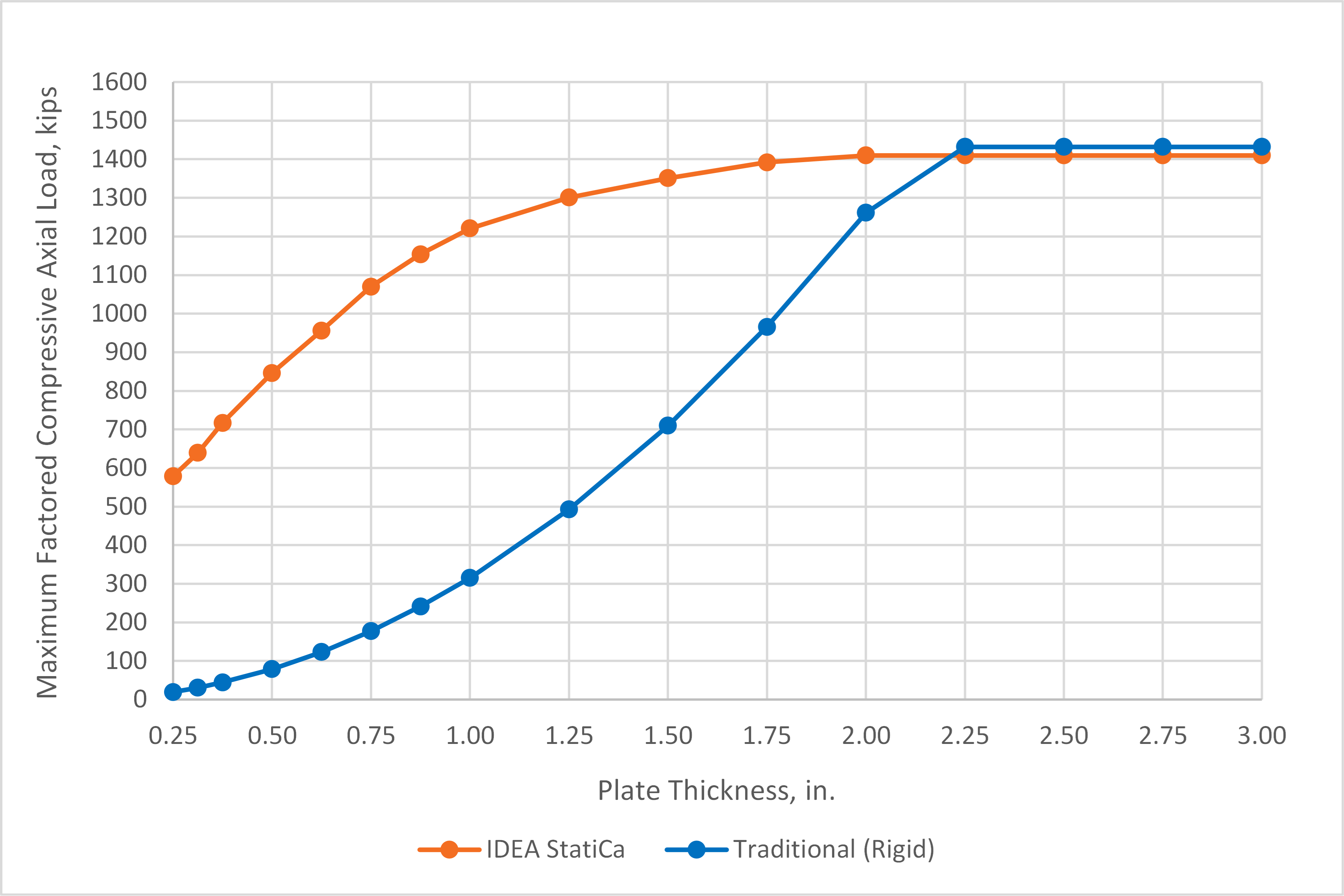
Fig. 6 Maximum factored compressive axial load vs. plate thickness for base plate with wide flange column
Also like for the HSS column base plate, a significant difference in strength is noted for the thinner base plates. A major source of the difference is the uniform bearing stress over the entire base plate assumed in the traditional calculations. An alternative approach to the traditional calculations, based on European practice, is to assume a uniform bearing stress over only a portion of the base plate. The portion of the base plate subject to bearing stress is the column cross section extended out by dimension c, as shown in Fig. 7.
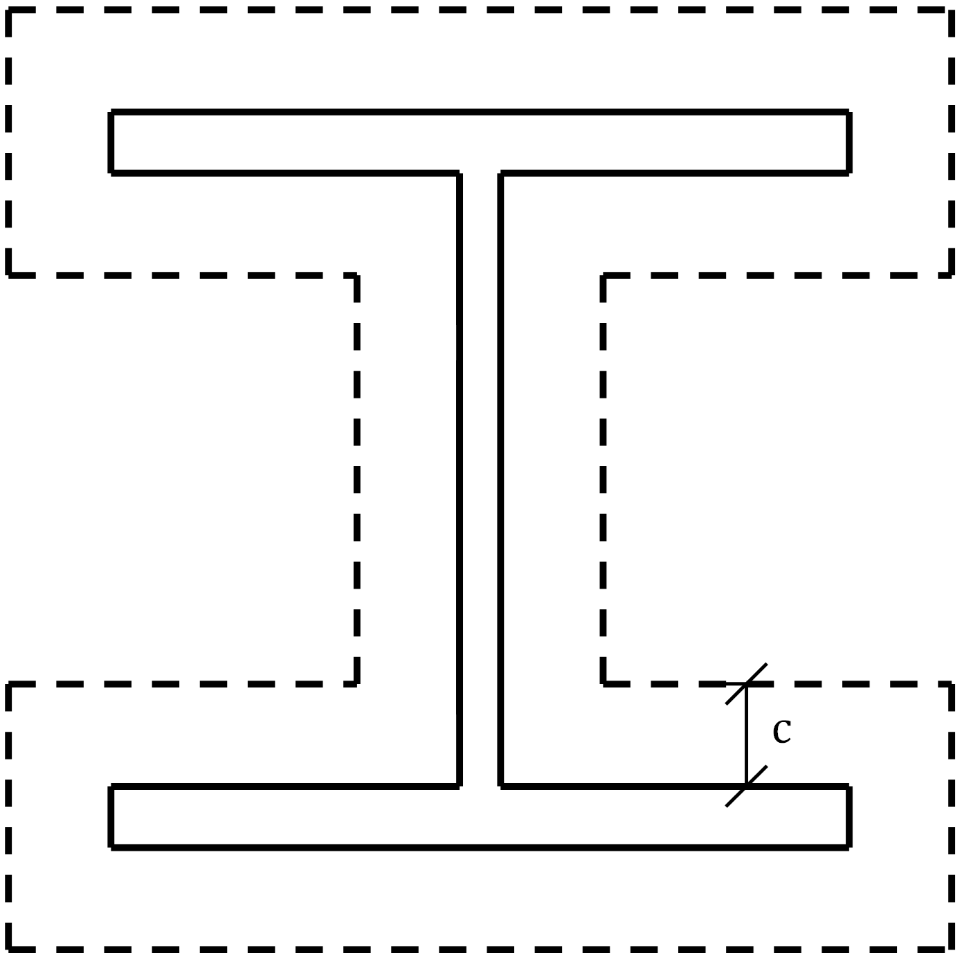
Fig. 7 Assumed bearing area for the traditional (flexible) calculations for base plate with wide flange column
In European practice, the dimension c is based on a cantilever beam analogy as the maximum uniformly loaded length that can support the bearing stress without yield. A value for the dimension c can be determined by applying this concept to this example and calculations used in US practice. The cantilever beam analogy is shown in Fig. 8. The uniform bearing stress is equal to 1.7 times the concrete compressive strength given that the plan area of the concrete is large in this example (i.e., \(\sqrt{A_2/A_1} \ge 2\)). The design bearing stress is \(\phi F_p = 1.105 f'_c\) after applying the resistance factor for concrete crushing of 0.65. The resulting required moment strength at the support for a unit width of the cantilever is
\[M_u=1.105f'_c \frac{c^2}{2}\]
The available moment strength for the limit state of flexural yielding for a unit width of the cantilever is
\[\phi M_n=0.9F_y \frac{t_p^2}{4}\]
Equating the required and available moment strengths (i.e., \(M_u=\phi M_n\)) results in an equation for c as a function of plate thickness.
\[c=0.638t_p \sqrt{\frac{F_y}{f'_c}}\]
For the material strengths used in this example, Fy = 36 ksi and f’c = 4 ksi, the value of c is 1.91tp for a ratio of c/tp = 1.91.
Fig. 8 Cantilever beam analogy for determination of dimension c
Steenhuis et al. (2008) evaluated the relative stiffness of the base plate and concrete foundation and recommended a ratio of c/tp = 1.5. Another potential value for the ratio is c/tp = 2.5, based on the 2.5:1 slope for the spread of load that is assumed in other aspects of steel design, e.g., the web local yielding provisions of Section J10.2 of the AISC Specification (2016).
The strengths of the base plate using the three different c/tp ratios are shown with the IDEA StatiCa results and the traditional calculation results using a rigid based plate assumption in Fig. 9. For the thinner base plates, the alternative bearing stress distribution permits maximum factored loads greater than when using the assumptions of AISC Design Guide 1. The strengths are closer to the strengths from IDEA StatiCa, but IDEA StatiCa still shows greater strength. There are two main reasons for this. First, the base plate does not behave as a cantilever between the flanges of the column. Using a bearing stress distribution based on the cantilever beam analogy in this region between the flanges is conservative. Second, IDEA StatiCa does not use a uniform bearing stress, even within the bearing area.
Fig. 9 Maximum factored compressive axial load vs. plate thickness for base plate with wide flange column including traditional calculations with flexible base plate
The distribution of bearing stress in IDEA StatiCa results from the relative stiffness of the base plate and concrete foundation. The bearing stress is greatest directly below the column web and flanges and decreases away from these elements as shown in Fig. 10. Thus, the distribution of bearing stress is not uniform as assumed in the cantilever beam analogy. Also, the peak bearing stress can exceed the uniform bearing stress used in design since IDEA StatiCa evaluates the utilization ratio based on the average bearing stress in the bearing area. The bearing area is defined in IDEA StatiCa as the area with a bearing stress greater than a fraction of the maximum bearing stress. The fraction, called the stress cut-off ratio, is taken as 0.1 by default, but can be set by the user in the code setup menu. Using a different stress cut-off ratio yields different results. The maximum factored compressive axial load per IDEA StatiCa using a stress cut-off ratio of 0.4 is shown in Fig. 9.
Fig. 10 Bearing stress distribution from IDEA StatiCa for base plate with WF column. Hatching indicates area A2 and extends beyond the view
Use of a uniform bearing stress over the whole base plate for base plates that are oversized for bearing is clearly conservative. Alternative approaches that account for base plate flexibility still include simplifying assumptions to allow for hand calculation. While IDEA StatiCa provides greater strengths than either of these methods, it is based on realistic assumptions of behavior and bearing strength checks are performed in accordance with the AISC Specification. Engineers who desire results that better match hand calculations can adjust the stress cut-off ratio in IDEA StatiCa to 0.4.
3 Shear Load
Base plates subjected to shear load are investigated in this section. The transfer of shear from a base plate to the concrete can occur through several mechanisms, including friction, bearing of the base plate or a shear lug against the concrete, and shear in the anchor rods. This study investigates only the mechanism of shear in the anchor rods.
As noted in AISC Design Guide 1, the design of anchor rods for shear depends on the connection details and corresponding load path. Holes in base plates for anchor rods typically have a larger tolerance than bolt holes to allow for misalignment of the rods during setting. Recommended sizes for anchor rod holes in base plates are presented in Table 14-2 of the AISC Manual (2017). To avoid slip and transfer the shear to all the anchor rods equally, a setting plate can be installed below the base plate or plate washers can be installed above the base plate (and below the anchor rod nuts). Once the setting plate or plate washers are welded to the base plate; the shear will be transferred uniformly to each of the anchor rods. However, if plate washers are used, bending of the anchor rod within the base plate should be considered in design.
IDEA StatiCa does not consider bending of the anchor rod within the base plate. A series of analyses were performed to demonstrate the effect of this bending. The analyses were performed with a W12x120 (ASTM A992, Fy = 50 ksi) column on a square base plate with plan dimensions of 18 in. by 18 in., thickness varying from 0.25 in. to 2.50 in., and steel conforming to ASTM A36 (Fy = 36 ksi). Anchor rods were 3/4 in. diameter (ASTM F1554 Gr. 36, Fy = 36 ksi) with threads not excluded from the shear plane and had an edge distance of c1 = 1.5 in. The holes for the anchor rods were 1-5/16 in. in diameter in accordance with the recommendations of Table 14-2 of the AISC Manual (2017). The base plate was assumed to bear on a 2 in. thick grout pad (mortar joint) above the concrete (f'c= 4 ksi). The plan area of the concrete was large such that edge effects did not need to be considered. The shear was applied with the point of zero moment at the top of the base plate.
Maximum factored shear loads from IDEA StatiCa and traditional calculations are presented in Fig. 11. The IDEA StatiCa results are nearly constant with a maximum factored shear load of 24 kips. This value is the available shear strength of the four anchor rods with a 0.8 reduction factor applied as required by the ACI Code (2019) for base plates with grout pads. This strength is appropriate when a setting plate is used, or the anchor rod holes do not have a large tolerance. However, if plate washers are used, the strength reduces with increasing base plate thickness. The traditional calculations were performed following the procedure laid out in Example 4.11 of AISC Design Guide 1 including a lever arm for bending of half the distance from the center of the plate washer to the top of the grout. As recommended in AISC Design Guide 1, the 0.8 reduction factor for grouted base plates defined in the ACI Code (2019) was not applied. For this case, the traditional approach per AISC Design Guide 1 results in lower maximum factored shear than IDEA StatiCa for base plates 3/8 in. and thicker. If using base plates with welded plate washers or other details that enable significant bending of the anchor rods within the base plate, it is recommended that checks be performed outside of IDEA StatiCa.
Fig. 11 Maximum factored shear load vs. plate thickness
4 Combined Axial Compressive Load and Moment
Base plates subjected to combined axial compressive load and moment are investigated in this section. The limit states evaluated for this loading condition are concrete bearing, flexural yielding of the base plate, tensile yielding of the anchor rod, and member strength.
The analyses were performed with a W12x120 (ASTM A992, Fy = 50 ksi) column on a square base plate with plan dimensions of 20 in. by 20 in., thickness varying from 0.5 in. to 2.50 in., and steel conforming to ASTM A36 (Fy = 36 ksi). Anchor rods were 1 in. diameter (ASTM F1554 Gr. 55, Fy = 55 ksi) embedded a sufficient depth in the concrete such that tensile strength of the anchor rod controlled over all concrete tensile failure modes. The anchor rods had an edge distance of c1 = 2 in. The holes for the anchor rods were 1-7/8 in. in diameter in accordance with the recommendations of Table 14-2 of the AISC Manual (2017). The base plate was assumed to bear on a 2 in. thick grout pad (mortar joint) above the concrete (f'c= 4 ksi). The plan area of the concrete was large such that edge effects did not need to be considered and the maximum permitted bearing strength would apply (i.e., \(\sqrt{A_2/A_1} \ge 2\)).
The applied axial compressive load was held constant at 100 kips and the maximum bending moment that can be applied concurrently was determined. The maximum factored bending moment is presented in Fig. 12. For IDEA StatiCa, the plastic strain limit on the tension side of the base plate controlled the strength of the connection with a 0.5 in. thick base plate. For the connection with a 0.625 in. thick base plate, an interesting limit state of concrete crushing controlled as the corners of the base plate on the tension side were bent down into the concrete by the anchors as shown in Fig. 13. The tensile strength of the anchors was reached at approximately 5% greater applied moment. The tensile strength of the anchors controlled for all other connections (i.e., tp ≥ 0.75 in.). With the traditional calculations, flexural yielding of the base plate on the compression side controlled the strength of the connections with plate thickness of 1.5 in. and less and tensile strength of the anchor rod controlled otherwise.
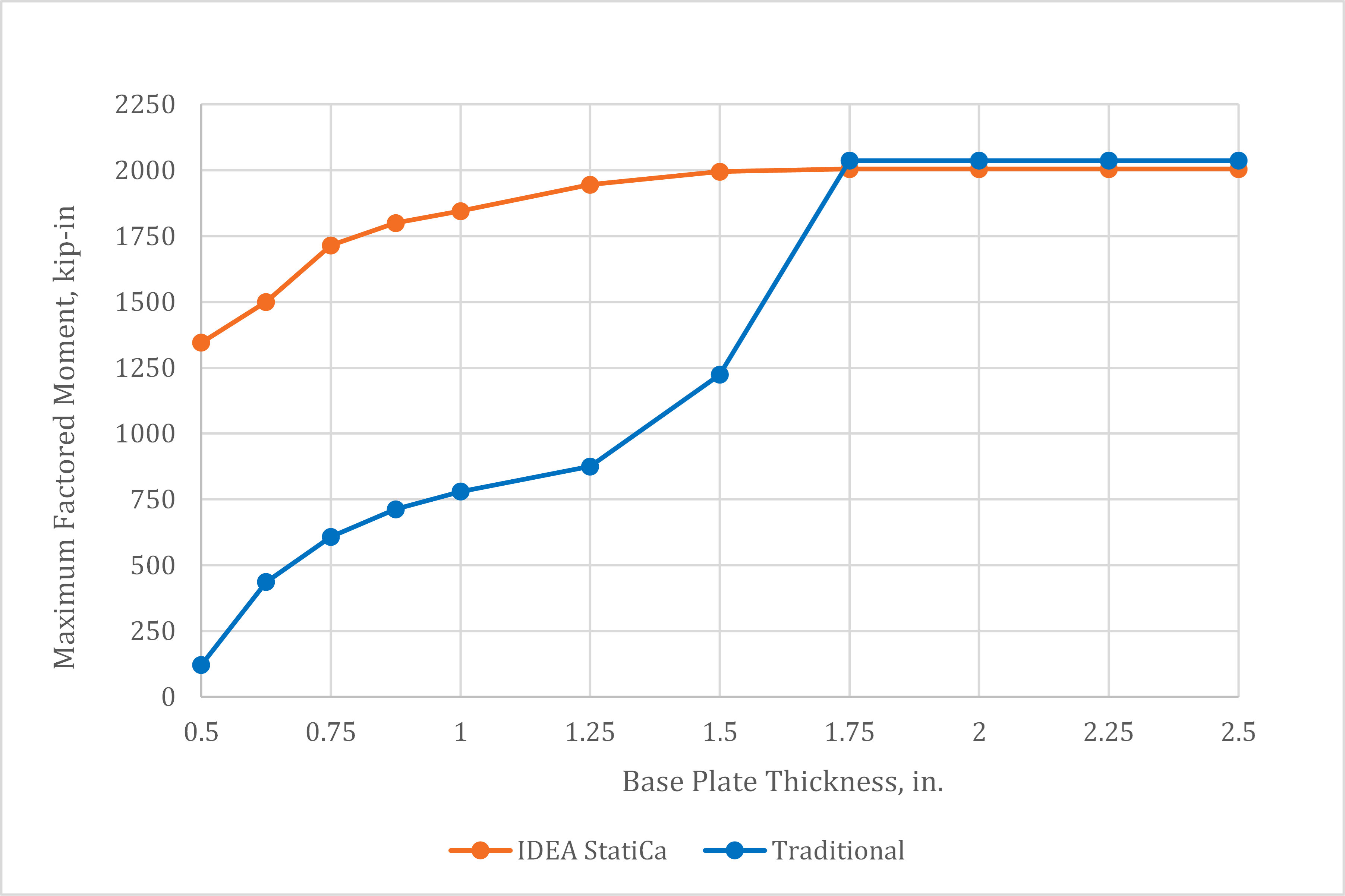
Fig. 12 Maximum factored moment vs. plate thickness for base plate with 100 kips axial compressive load
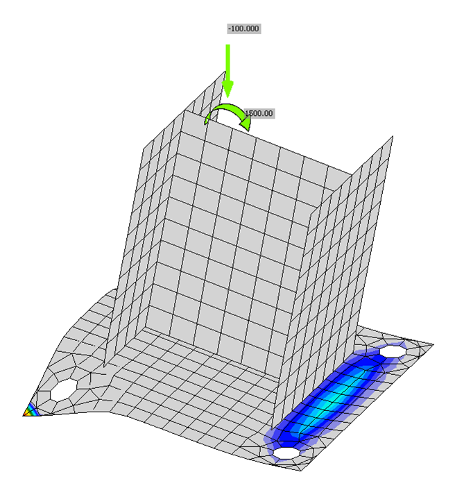
Fig. 13 Deformed shape (scale factor = 5) and concrete bearing stress for base plate connection with 0.625 in. thick base plate. Note bearing stresses at corners of the tension side of the base plate
Where base plate bending controlled the traditional calculations, the maximum permitted factored moments were less for the traditional method than for IDEA StatiCa. The reason for this result is similar to that for the base plates subjected to concentric axial load, specifically, that the assumed distribution of bearing stress is conservative and does not account for increased flexibility of the base plate upon yield. Traditional calculation methods have been developed for evaluating flexible base plates subject to axial compression and bending and have been compared to IDEA StatiCa in other studies.
Conversely, where the tensile resistance of the anchor rod controlled the traditional calculations, the maximum permitted factored loads were slightly greater for the traditional method than for IDEA StatiCa. The available tensile strength of the anchor rods is slightly greater for the traditional calculations since it is based on recommendations from AISC Design Guide 1 while IDEA StatiCa is based on provisions from the ACI Code. The two approaches also vary in the assumed bearing stress distribution resulting in slightly different lever arm for the force couple formed between the anchor rod and the centroid of the bearing force.
5 Summary
This study compared the design of base plate connections by traditional calculation methods used in US practice and IDEA StatiCa. Key observations from the study include:
- For thick base plates that better conform to the rigid base plate assumption, IDEA StatiCa provides strengths that are comparable to the traditional calculations presented in AISC Design Guide 1.
- For thinner base plates, where flexural yielding of the base plate due to bearing stresses controls, IDEA StatiCa can provide significantly greater strengths than the traditional calculations since the distribution of bearing stresses is calculated explicitly and redistributes upon the initiation of yielding of the base plate.
- IDEA StatiCa correctly calculates the shear strength of anchor rods but neglects the potential reductions in shear strength due to bending of the anchor rod within the base plate that can occur in certain base plate configurations (e.g., base plates with welded plate washers).
References
ACI. (2019). Building Code Requirements for Structural Concrete and Commentary. American Concrete Institute, Farmington Hills, MI.
AISC. (2016). Specification for Structural Steel Buildings. American Institute of Steel Construction, Chicago, Illinois.
AISC. (2017). Steel Construction Manual, 15th Edition. American Institute of Steel Construction, Chicago, Illinois.
Fisher, J., and Kloiber, L. (2006). Base Plate and Anchor Rode Design, 2nd Edition. Design Guide 1, American Institute of Steel Construction, Chicago, Illinois.
Fitz, M., Appl, J., Geibig, O. (2018). “Comprehensive base plate and anchor design based on realistic behavior – new design software based on realistic assumptions.” Stahlbau 87(12), 1179-1186. [In German] https://doi.org/10.1002/stab.201800036
Steenhuis, M., Wald, F., Sokol, Z., and Stark, J. (2008). “Concrete in Compression and Base Plate in Bending.” Heron, 53(1/2), 51–68.