Assemblages acier d'éléments à section creuse
Les assemblages d'éléments à section creuse peuvent subir des déformations importantes tout en étant capables de supporter des charges encore plus élevées. D'autre part, les plaques peuvent flamber dans le domaine inélastique, pour lequel une analyse géométriquement et matériellement non linéaire est mise en œuvre.
Déformation hors plan
L'un des critères de l'état limite ultime des assemblages de sections creuses est la déformation hors plan de la section transversale creuse. La vérification est disponible dans le logiciel (dans la Configuration du code en tant que vérification de la déformation locale, activée par défaut pour les éléments porteurs creux). Elle est reconnue par les guides de conception CIDECT. Les limites sont de 3 % de la plus petite dimension de la section transversale (0,03 d0 pour les CHS et 0,03 b0 pour les RHS) pour l'état limite ultime et de 1 % pour l'état limite de service.
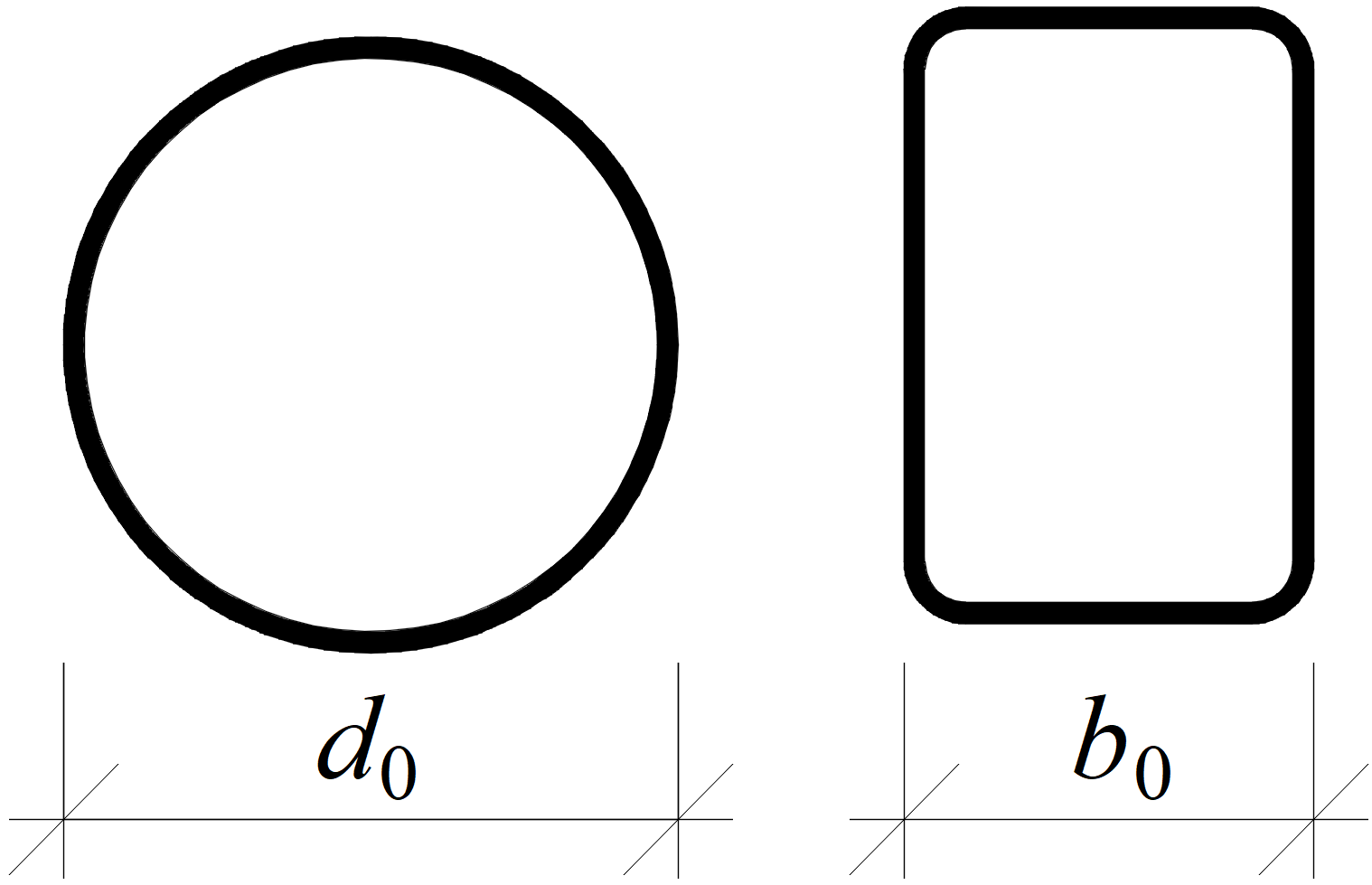
Définition des dimensions de la section transversale pour les sections creuses circulaires (CHS) et rectangulaires (RHS)
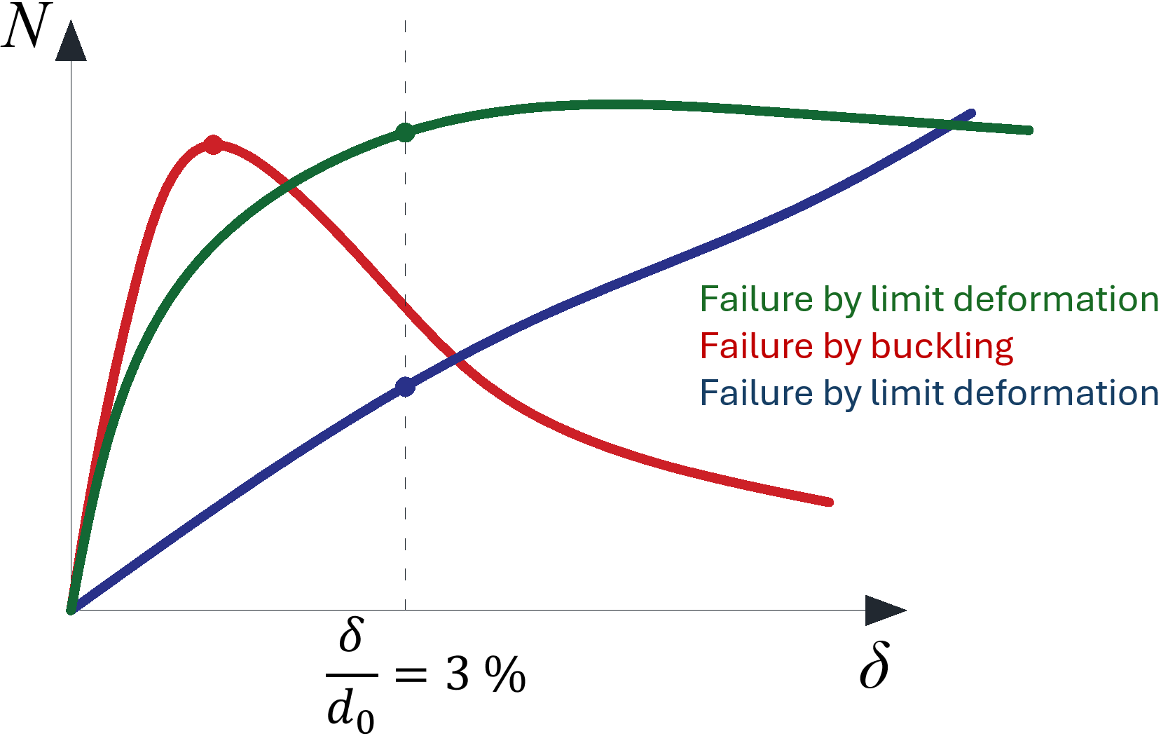
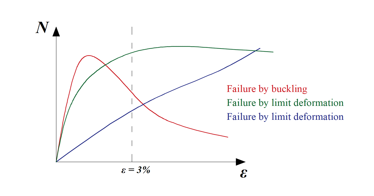
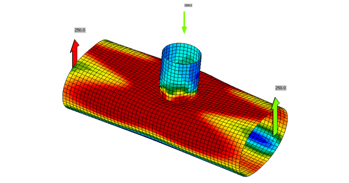
Diagrammes charge-déformation typiques pour les assemblages de sections creuses ; la courbe rouge correspond à un élément à paroi mince chargé en compression, la courbe verte à des éléments courants chargés en compression, la courbe bleue correspond par exemple à un assemblage en X chargé en traction
Analyse géométriquement et matériellement non linéaire (GMNA)
Dans le cas de certains assemblages de sections creuses, notamment avec un rapport diamètre/épaisseur élevé, l'analyse géométriquement linéaire peut ne pas reproduire le comportement de l'assemblage avec une précision suffisante, et sa résistance aux charges peut être sous-estimée ou surestimée. Il est recommandé d'utiliser une analyse géométriquement et matériellement non linéaire plus avancée pour les assemblages de sections creuses, même si le temps de calcul est légèrement plus élevé. Si l'analyse GMNA pour les sections creuses est sélectionnée dans la Configuration du code, la GMNA est utilisée à la place de l'analyse géométriquement linéaire et matériellement non linéaire (MNA, utilisée en standard dans IDEA Statica Connection) pour les modèles comportant un élément à section creuse comme élément porteur.
Remarque : Si l'élément porteur n'est pas une section creuse, le solveur GMNA est désactivé pour l'analyse de l'ensemble du modèle d'assemblage, quels que soient les paramètres de la configuration du code (GMNA activée ou désactivée).
Déformation de la section transversale à l'extrémité du modèle coques
La section transversale peut se déformer aux extrémités du modèle constitué d'éléments coques. Les assemblages de sections creuses nécessitent des éléments relativement longs – jusqu'à 10 fois le diamètre de la section transversale. Un superélément condensé est placé derrière la partie du modèle constituée d'éléments coques. Cela permet un calcul plus rapide avec la même précision que le modèle complet constitué d'éléments coques. Le superélément condensé possède uniquement des propriétés de matériau élastique, ce qui signifie que les déformations plastiques dues au mode de rupture étudié ne doivent pas atteindre l'extrémité du modèle d'éléments coques. Pour cette raison, le modèle coques s'étend par défaut sur 1,25 fois la hauteur de la section transversale (modifiable dans la Configuration du code) au-delà de la dernière opération de fabrication.
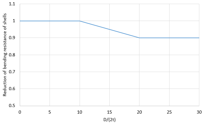
Résistance à la flexion des coques réduite pour les sections creuses (imperfections)
Les résistances aux charges des assemblages de sections creuses dans les normes sont déterminées par la méthode des modes de rupture, qui utilise des modèles d'ajustement de courbes établis à partir d'essais et de modèles numériques avancés. La structure réelle contient des imperfections initiales et des contraintes résiduelles, qui ne sont pas prises en compte par les modèles coques dans IDEA StatiCa Connection. Afin d'obtenir une meilleure conformité avec les résultats des normes, l'influence des contraintes résiduelles et des imperfections initiales est simulée en réduisant la résistance à la flexion des coques de sections creuses présentant un rapport D/(2t) élevé.