Analyse de fatigue dans la conception structurelle
L'analyse de fatigue ne fournit pas de résistance finale ni de nombre de cycles que le détail peut supporter. Elle fournit uniquement des données d'entrée pour des calculs ultérieurs conformément aux normes.
Au minimum, deux cas de charge doivent toujours être définis. Le premier cas de charge est le cas de référence. Il est supposé représenter, par exemple, le poids propre de la structure et peut contenir des charges nulles. Les autres cas de charge simulent les actions de fatigue. La contrainte nominale normale et de cisaillement fournie par IDEA StatiCa est la plage de contraintes entre l'action de fatigue, par exemple LE2, et le cas de charge de référence.
Par exemple, la contrainte de cisaillement en un certain point est de 50 MPa dans le cas de charge de référence et de 180 MPa dans LE2. La contrainte de cisaillement nominale affichée en ce point est :
\[\tau = 180-50=130\, \textrm{MPa}\]
Notez qu'il ne doit pas y avoir de plastification des plaques due aux actions de fatigue, sinon les plages de contraintes sont faussées.
Les contraintes sont disponibles pour :
- Boulons
- Soudures
- Plaques
Boulons
Pour les boulons, les contraintes sont déterminées simplement en divisant la force par l'aire correspondante :
- \(\sigma = F_t / A_s \)
- \(\tau = V / A \)
où :
- \(F_t\) – effort de traction dans le boulon
- \(A_s\) – aire de la section résistante en traction du boulon
- \(V\) – effort tranchant dans le boulon ; en présence de plusieurs plans de cisaillement, l'effort tranchant le plus élevé est utilisé
- \(A\) – aire du boulon résistant au cisaillement ; aire de la section résistante en traction si les filets sont interceptés par le plan de cisaillement, sinon aire de la section brute
Soudures
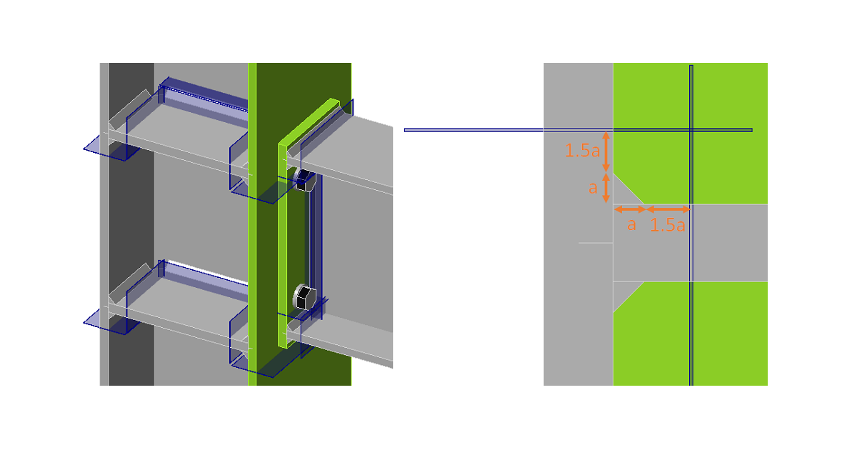
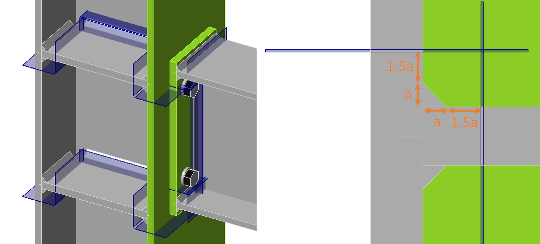
Les soudures dans CBFEM sont constituées d'un élément de soudure avec des contraintes multipoints reliant les plaques. La distribution des contraintes dans la soudure est perturbée par ces contraintes, et par conséquent, les contraintes sont relevées à partir d'une section située à 1,5 fois la dimension de la gorge depuis le pied de soudure. Trois sections sont créées pour une soudure d'angle double face. Deux sections appartiennent à la même catégorie de détail, et seule la plus sollicitée est affichée. La contrainte normale maximale et la contrainte de cisaillement correspondante au même emplacement, ainsi que la contrainte de cisaillement maximale et la contrainte normale correspondante au même emplacement, sont affichées.
Voir également les améliorations de l'analyse de fatigue dans la version 22.0.
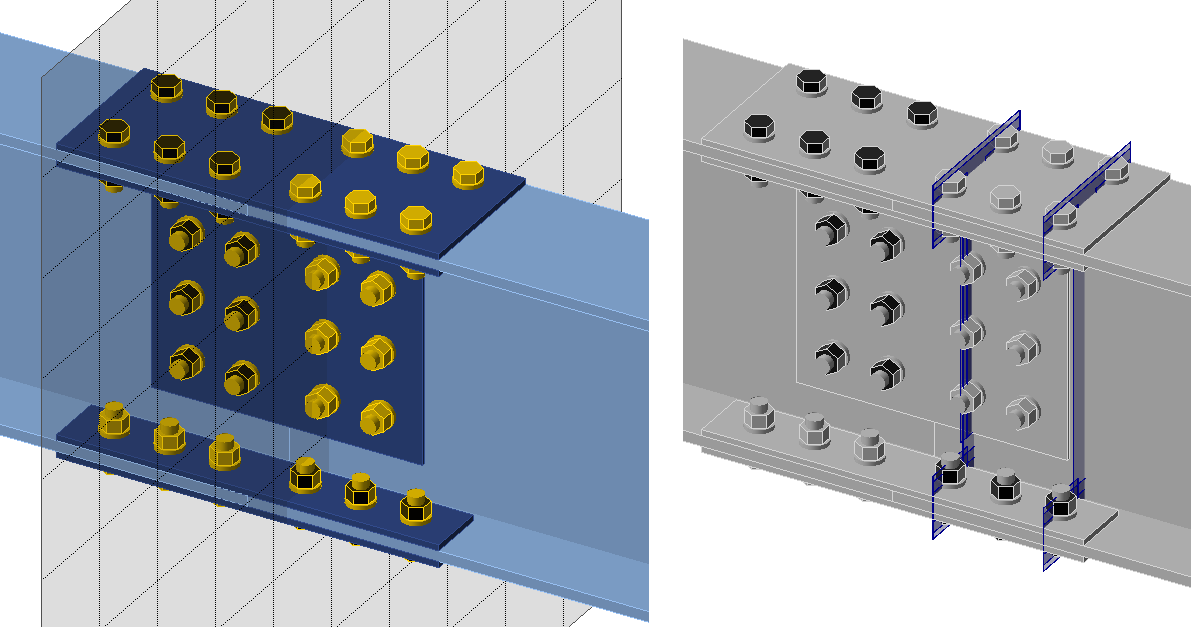
Plaques
La contrainte dans les plaques peut être visualisée en créant une section définie par l'utilisateur à l'aide d'une opération de fabrication par plan de travail (Workplane). Dans la figure ci-dessous, deux plans de travail ont été créés pour visualiser les contraintes autour des trous de boulons. La contrainte normale maximale et la contrainte de cisaillement correspondante au même emplacement, ainsi que la contrainte de cisaillement maximale et la contrainte normale correspondante au même emplacement, sont affichées.