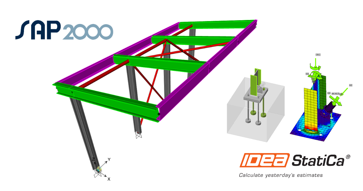
SAP2000 BIM link pour la conception structurelle d'un assemblage acier (AISC)
Comment activer le lien
- Téléchargez et installez la dernière version de IDEA StatiCa
- Vérifiez que vous utilisez une version autorisée de votre solution MEF/BIM
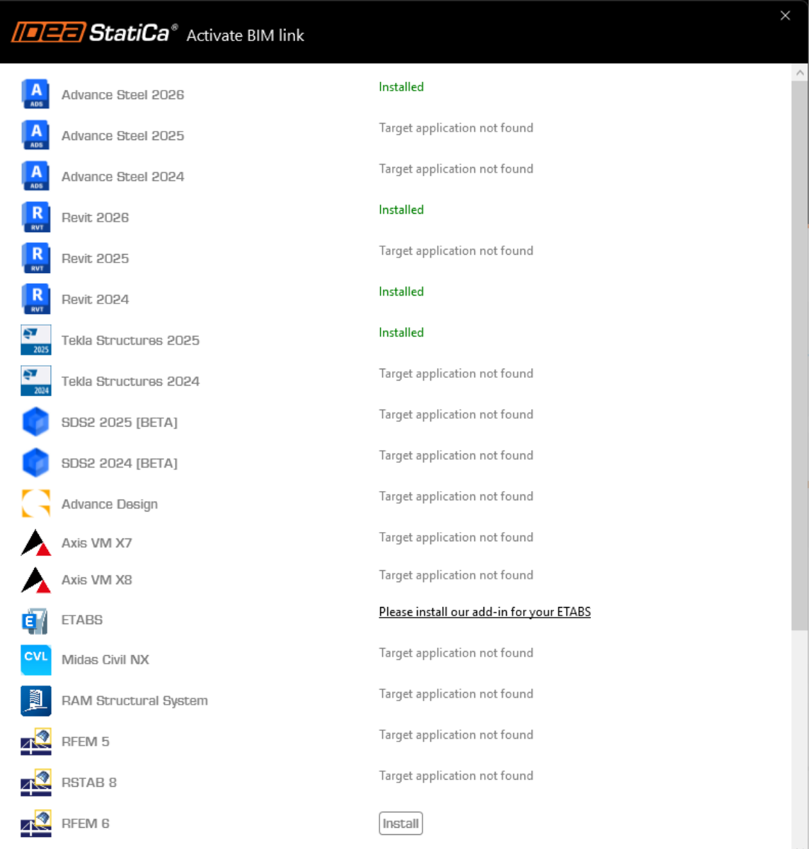
IDEA StatiCa intègre les liens BIM dans vos solutions MEF/BIM lors de l'installation. Vous pouvez voir le statut et activer autres liens BIM pour des logiciels installés aussi plus tard dans l'outil d'installation des liens BIM.
Veuillez noter qu'il faut des étapes supplémentaires pour activer des liens BIM de quelques solutions MEF avec IDEA StatiCa.
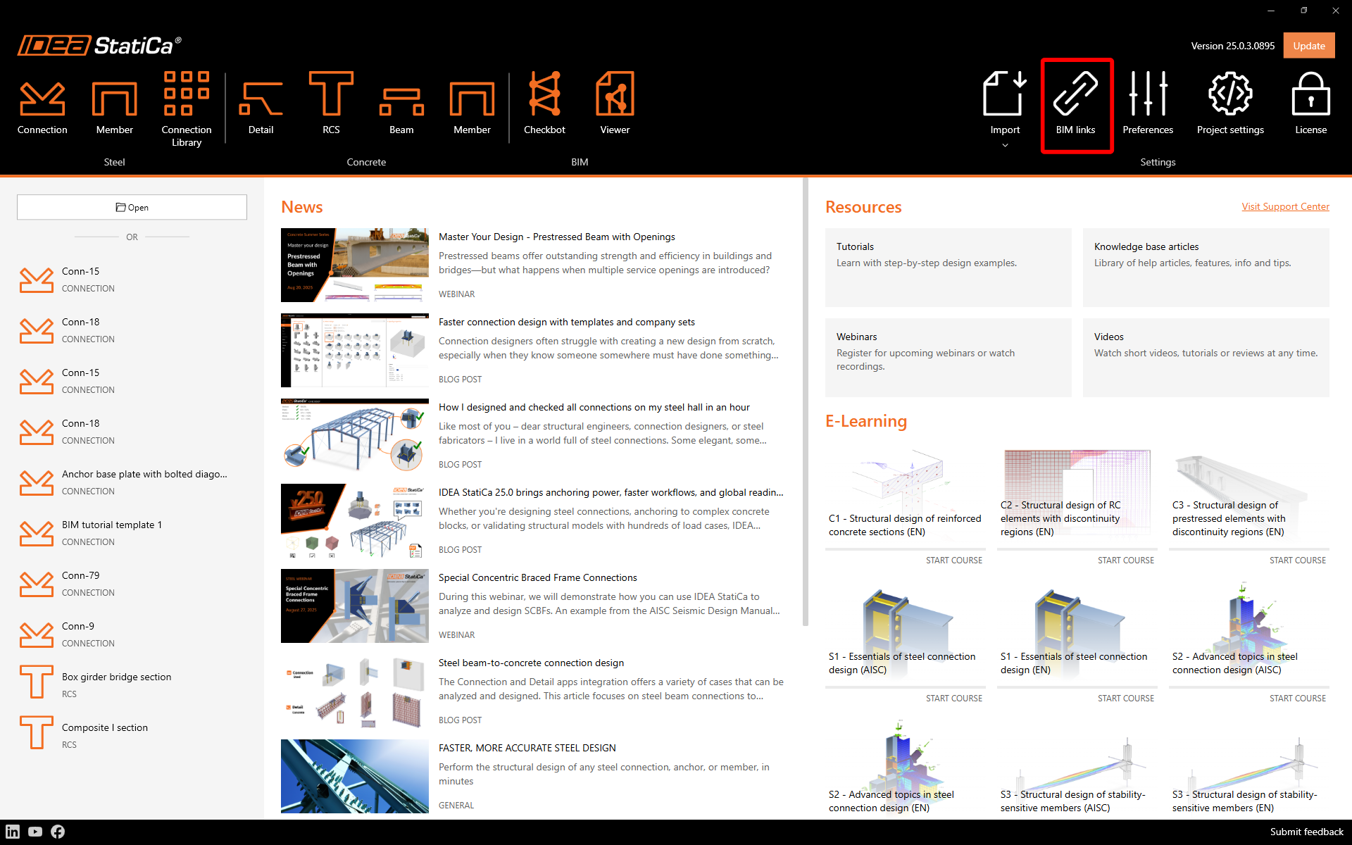
Ouvrez IDEA StatiCa et allez à l'onglet BIM et ouvrez l'outil d'installation des liens BIM (Activation du lien BIM...).
Une notification avec le texte « Voulez-vous autoriser cette application à apporter des modifications à votre appareil ? » peut apparaître. Dans ce cas, veuillez confirmer avec le bouton Oui.
Le lien BIM pour le logiciel sélectionné (si trouvé) sera installé. L'écran vous montrera aussi le statut d'autres liens BIM qui peuvent être déjà installés.
Des étapes manuelles supplémentaires sont requises dans SAP2000 pour finaliser la procédure d'intégration. Celles-ci varient selon la version de SAP2000 :
- Activation du lien BIM pour SAP2000 (v23 et versions ultérieures)
- Activation du lien BIM pour SAP2000 (v22 et versions antérieures)
Comment utiliser le lien
Ouvrez le projet AISC dans SAP2000 joint et lancez le calcul.
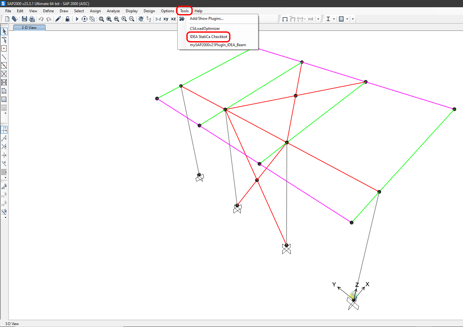
Le lien BIM devrait déjà être intégré. Vous pouvez le trouver dans le ruban supérieur sous Tools -> IdeaSAP2000v1PluginWrapper. Cela ouvrira l'application Checkbot .
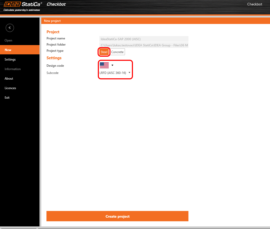
Sélectionnez l'option Nouveau avec le type de projet Acier, le code de calcul AISC et le sous-code LRFD (AISC 360-16). Cliquez ensuite sur Créer le projet.
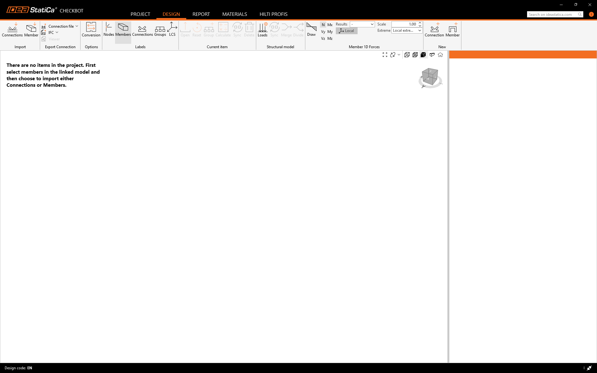
Le nouveau projet Checkbot est prêt à importer des assemblages depuis SAP2000.
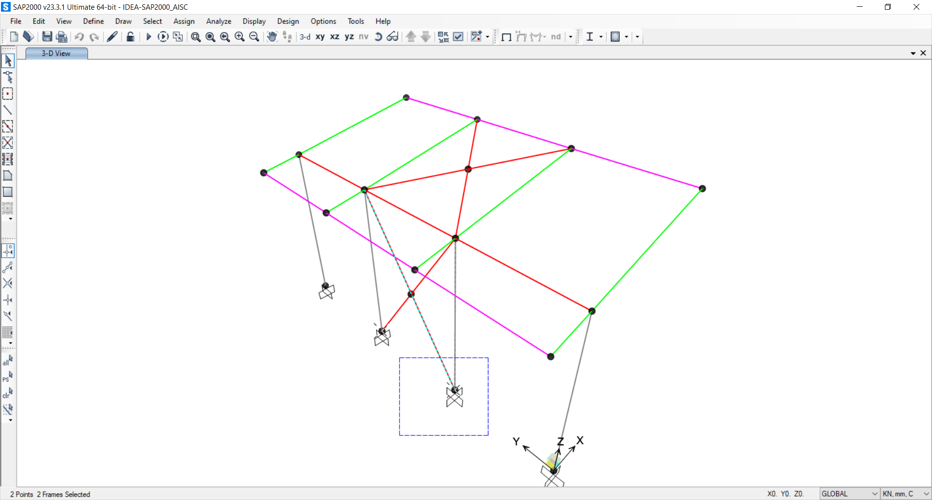
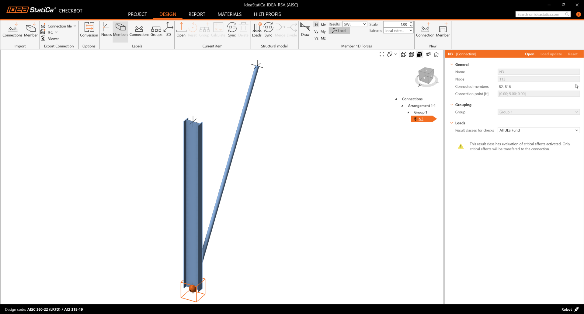
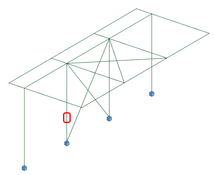
Dans SAP2000, sélectionnez l'un des poteaux intérieurs en veillant à sélectionner également le nœud inférieur.
Importer
Ensuite, dans Checkbot, sélectionnez Connections.
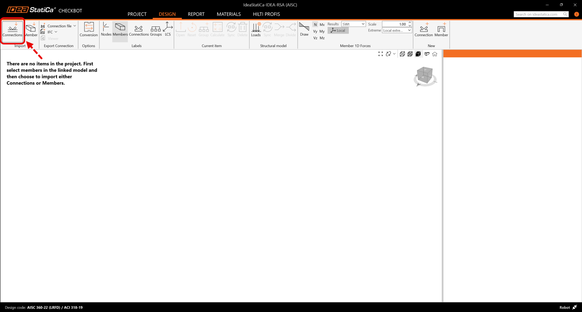
Cela importera le poteau et ses effets de charge dans Checkbot - avec les mêmes coordonnées, orientations et dimensions de section que dans le modèle EF.
Veuillez noter que la numérotation de vos nœuds et éléments peut être différente.
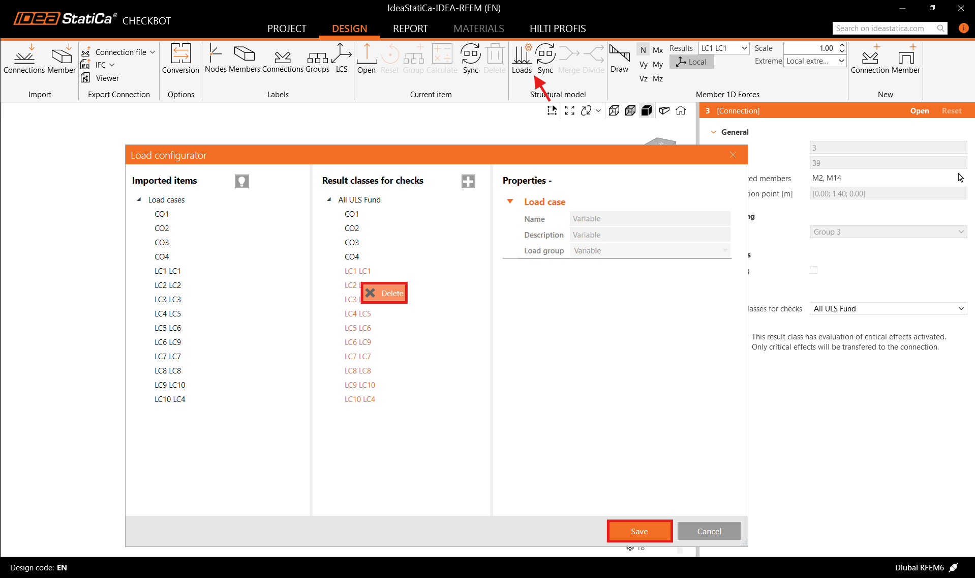
Avant de lancer l'analyse, assurez-vous de vérifier les classes de résultats pour les vérifications normatives et d'ajuster les cas de charge en conséquence. Dans la boîte de dialogue Load configurator, vous pouvez voir tous les cas de charge et combinaisons de charges importés à gauche, ainsi que les classes de résultats utilisées pour les vérifications normatives au centre. Si certains cas de charge ne sont pas pertinents pour votre vérification de conception, excluez-les en faisant un clic droit sur les charges sélectionnées et en les supprimant de la liste des classes de résultats.
Veuillez noter que l'espace de travail 3D est conçu pour afficher une vue d'ensemble de la structure importée et non une vue détaillée des assemblages réels. Pour plus d'informations sur Checkbot, voir ici.
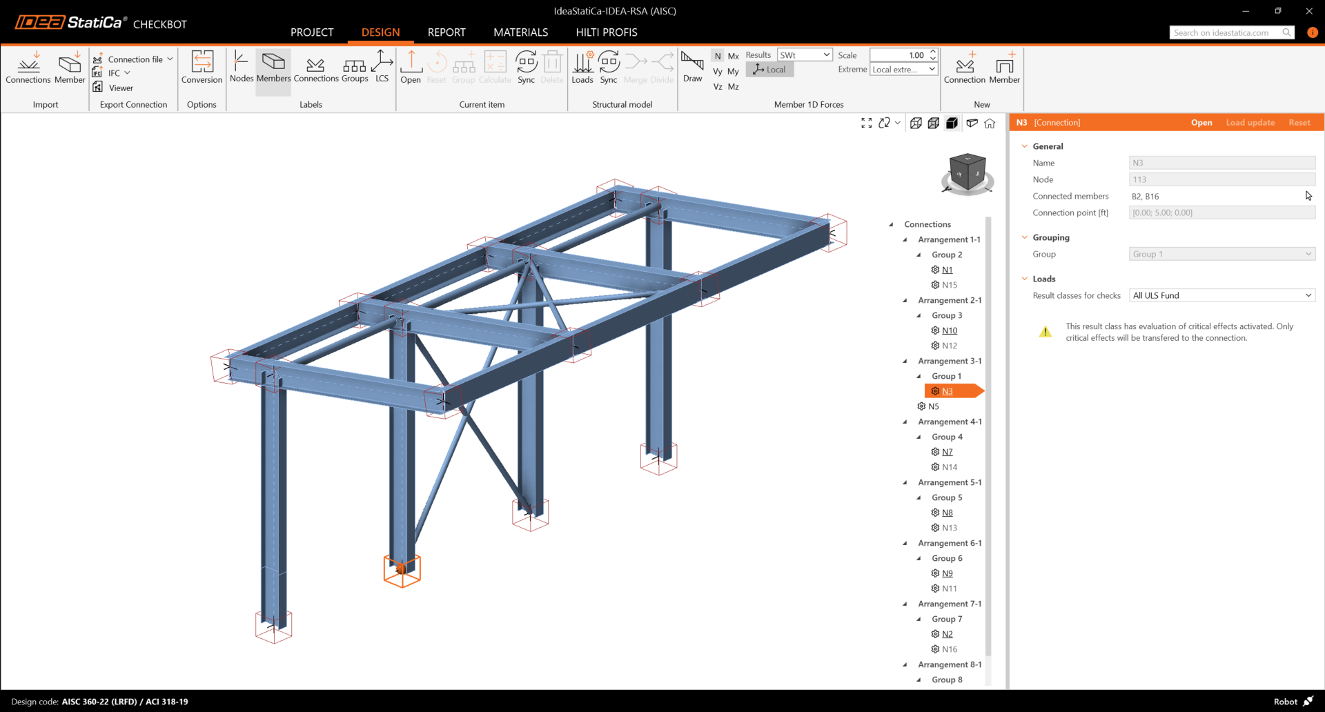
Pour plusieurs solutions EF, vous pouvez également importer plusieurs assemblages dans Checkbot de la même manière que ci-dessus. Au lieu de sélectionner un nœud et les éléments connectés, vous pouvez sélectionner plusieurs nœuds et éléments et les importer tous en même temps.
Géométrie
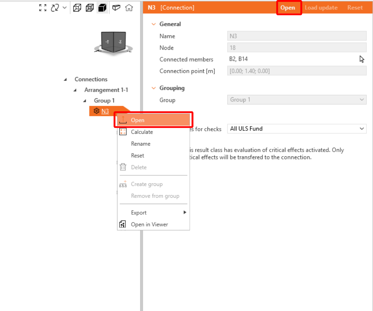
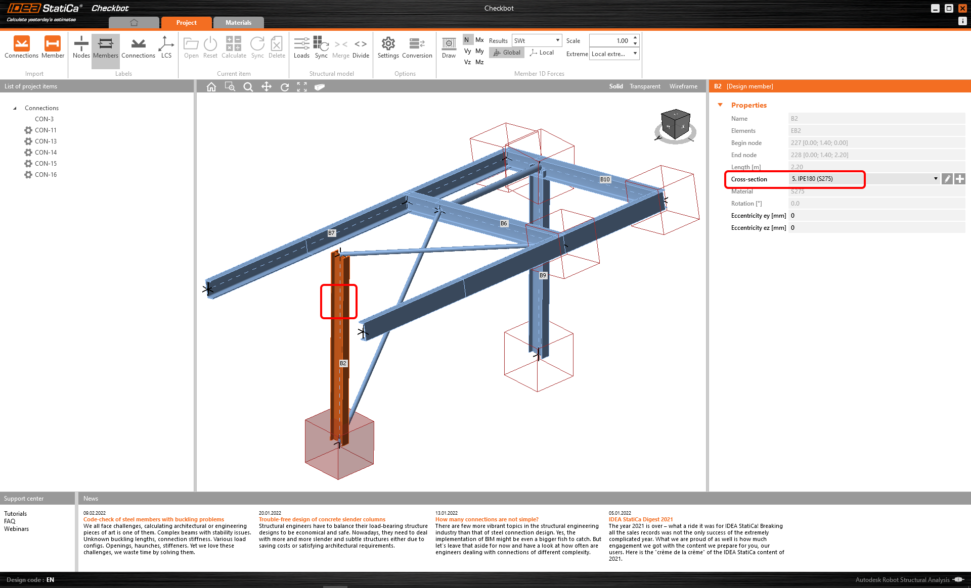
Dans la liste des éléments du projet sous Assemblages, avec un assemblage sélectionné dans Checkbot, vous pouvez soit faire un clic droit et sélectionner Ouvrir soit cliquer sur la commande du ruban Ouvrir pour commencer la conception, la vérification normative et la génération de rapports.
Les paramètres des éléments sont repris de l'application EF d'origine. Vous pouvez toutefois modifier la section de n'importe quel élément dans l'écran principal de Checkbot, mais cela rompra le lien avec l'application EF pour cette session, sauf si une nouvelle synchronisation est effectuée.
L'assemblage importé est ouvert dans l'application IDEA StatiCa Connection.
Il est possible que vous ne voyiez aucun effet de charge ou des effets de charge différents de ceux de votre solution EF, selon la façon dont les combinaisons de cas de charge ont été définies. Par défaut, IDEA StatiCa choisira les plus critiques pour les besoins de la vérification normative. (* Certaines solutions BIM ne sont pas en mesure de stocker les résultats des combinaisons de cas de charge.)
Pour plus d'informations sur les effets de charge, voir ici.
Calcul
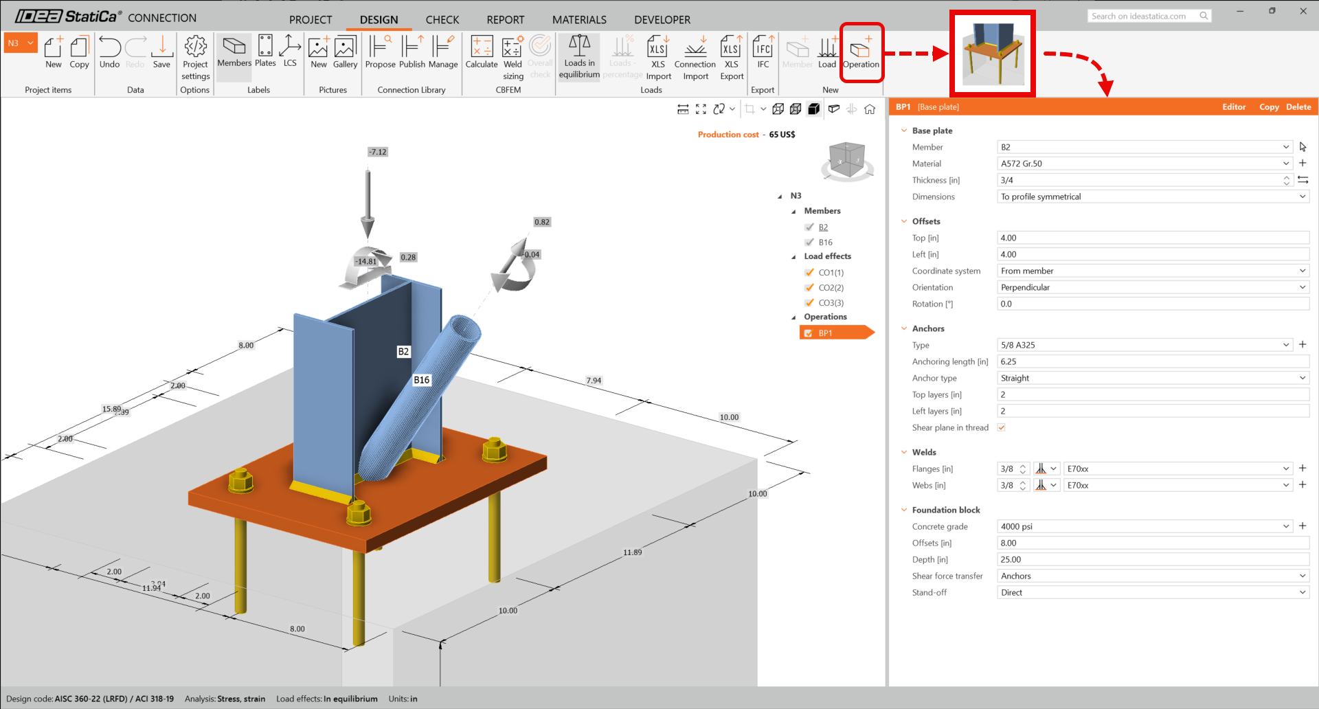
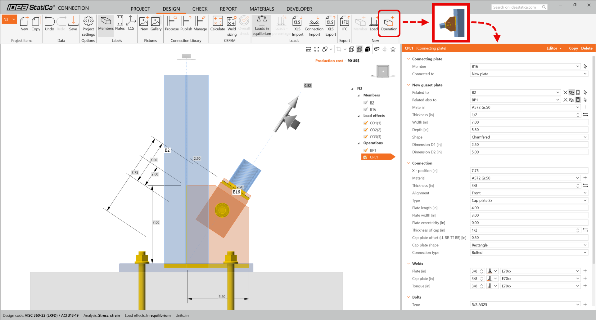
Pour créer l'assemblage avec platine de base, nous allons utiliser les opérations de fabrication. Dans le ruban supérieur, sélectionnez Opération, choisissez les opérations Platine de base et Plaque de connexion, et ajustez les paramètres comme indiqué ci-dessous :
Platine de base
Plaque de connexion
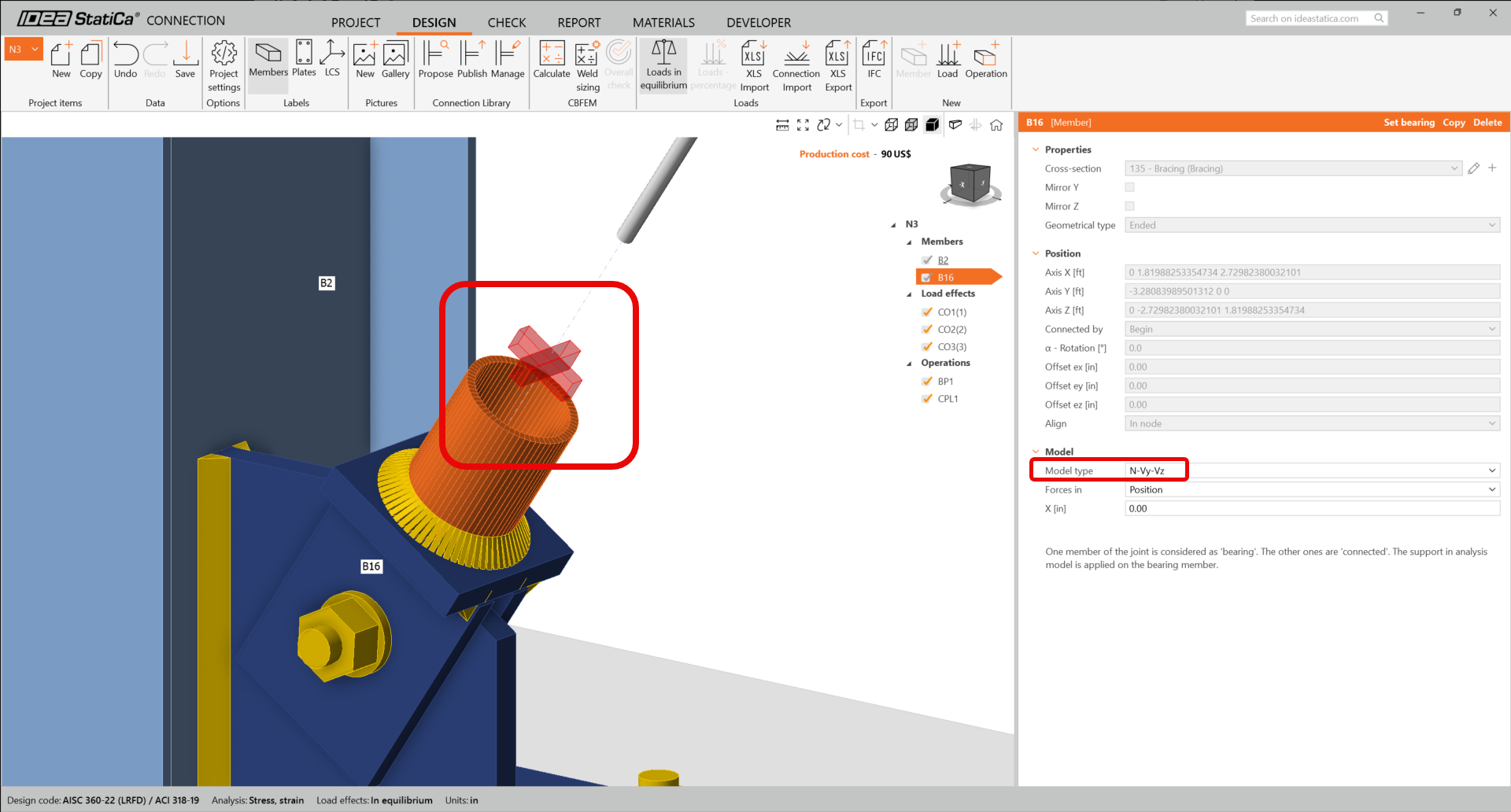
Comme nous avons raccordé la diagonale de contreventement à l'aide d'un assemblage à boulon unique, nous devons également modifier le Type de modèle de l'élément de contreventement en N-Vy-Vz. Sélectionnez le contreventement dans la liste des éléments et modifiez le type de modèle dans la liste déroulante.
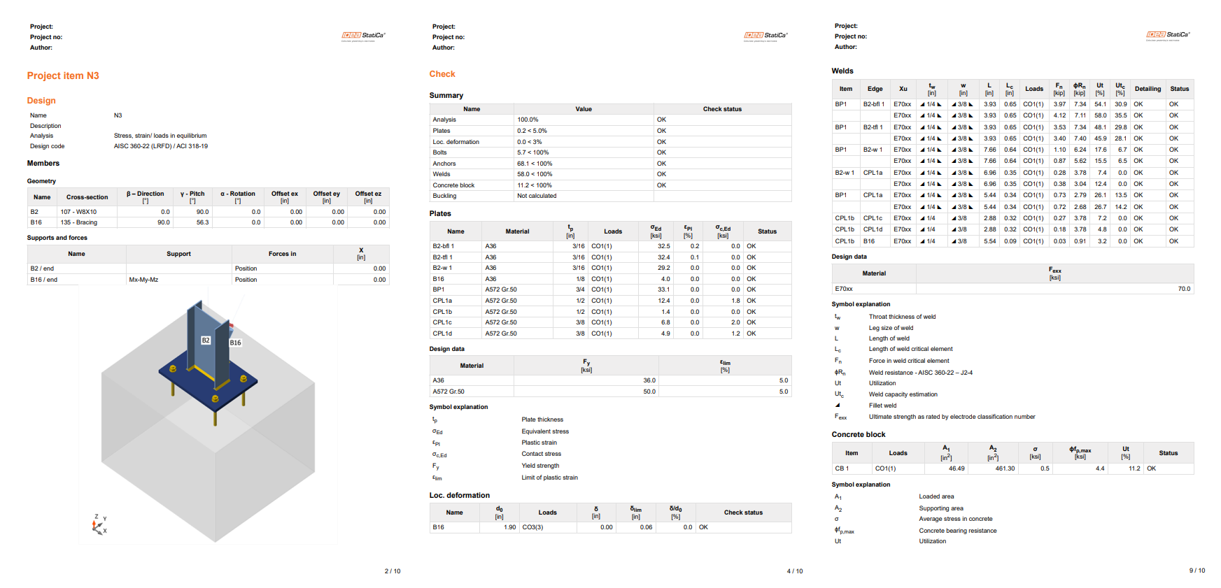
Voici à quoi ressemble l'assemblage calculé.
Vérification normative et rapport
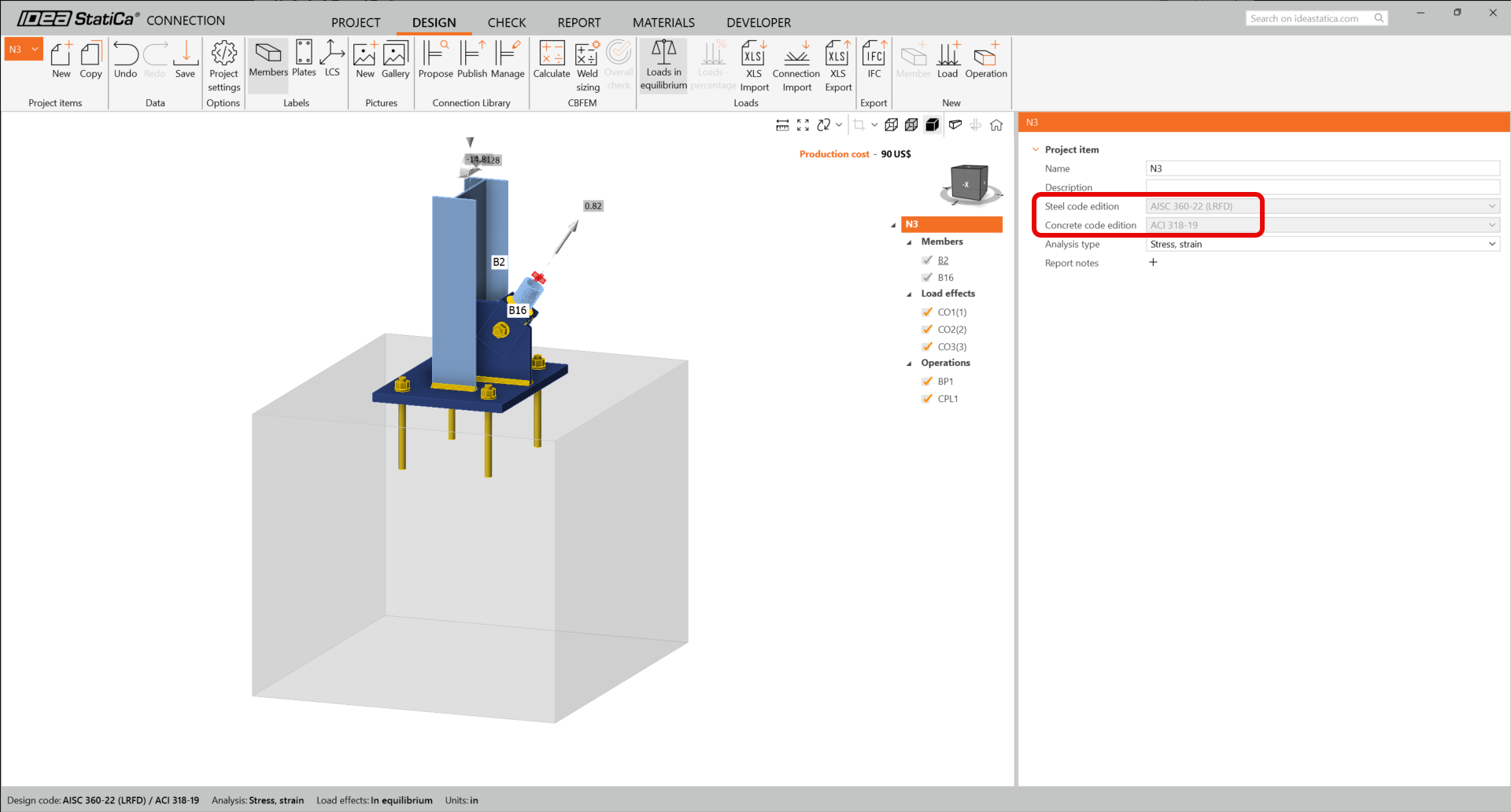
Pour lancer une vérification normative, nous devons également nous assurer que la norme est correcte dans IDEA StatiCa Connection. Dans l'onglet Calcul du label d'assemblage N3, vérifiez que LRFD 2022 est bien utilisé.
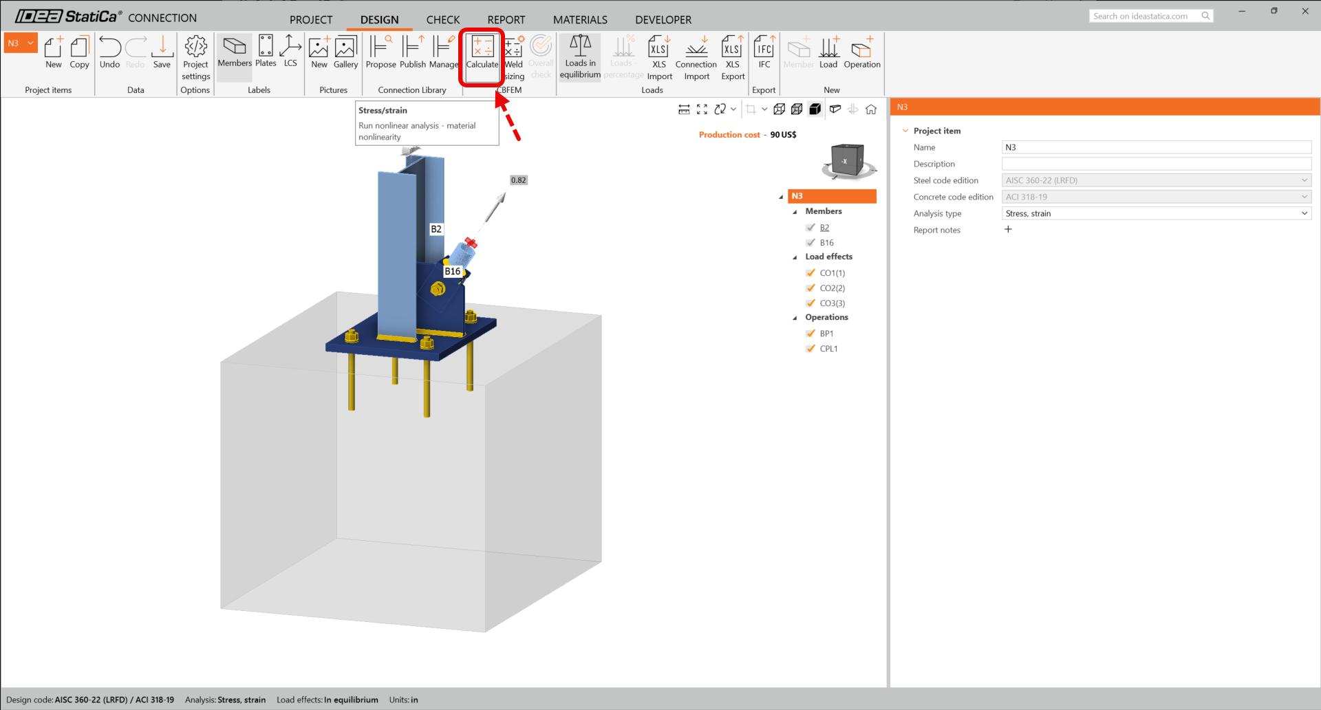
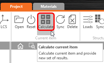
Lancez maintenant une vérification normative à l'aide de l'icône Calculer dans le panneau CBFEM du ruban supérieur.
Dans IDEA StatiCa Connection, vous pouvez effectuer de nombreux types d'analyses et de vérifications normatives. Pour plus d'informations, veuillez consulter cette page.
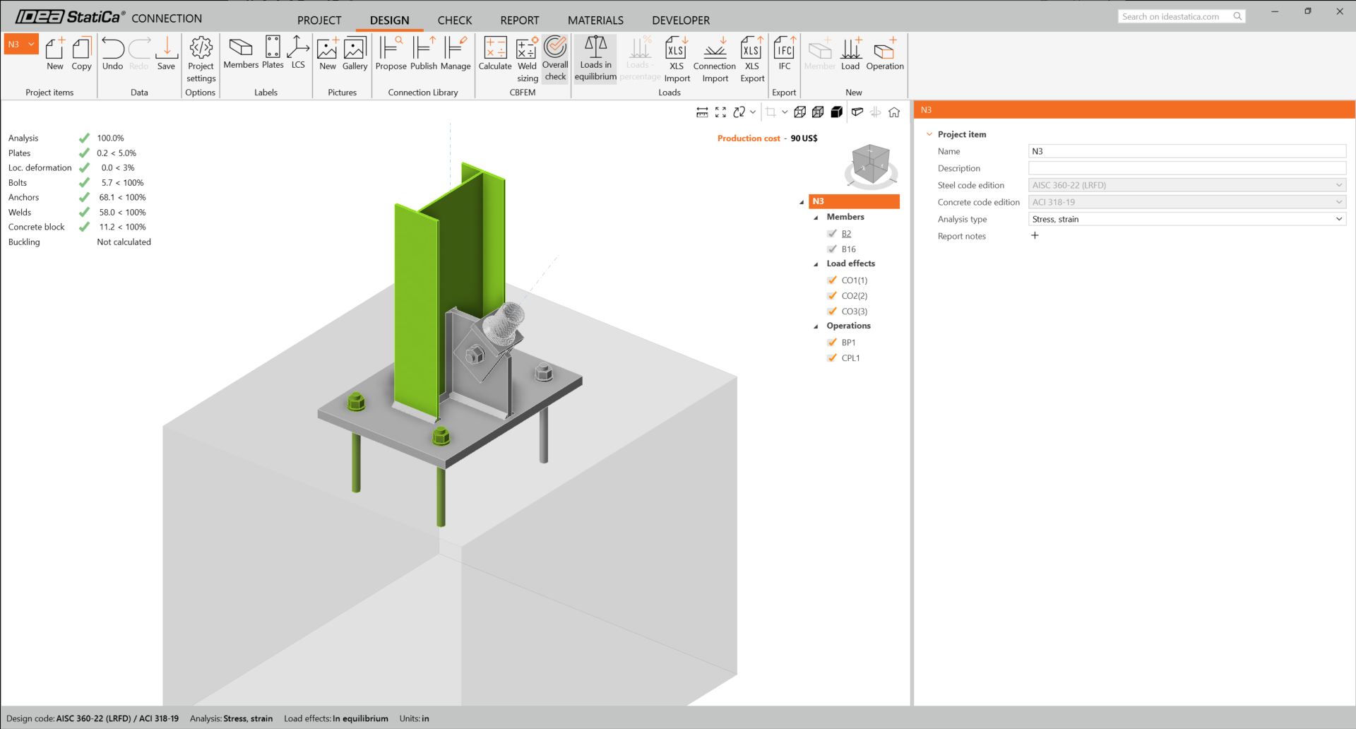
Vous obtiendrez les résultats de l'analyse non linéaire.
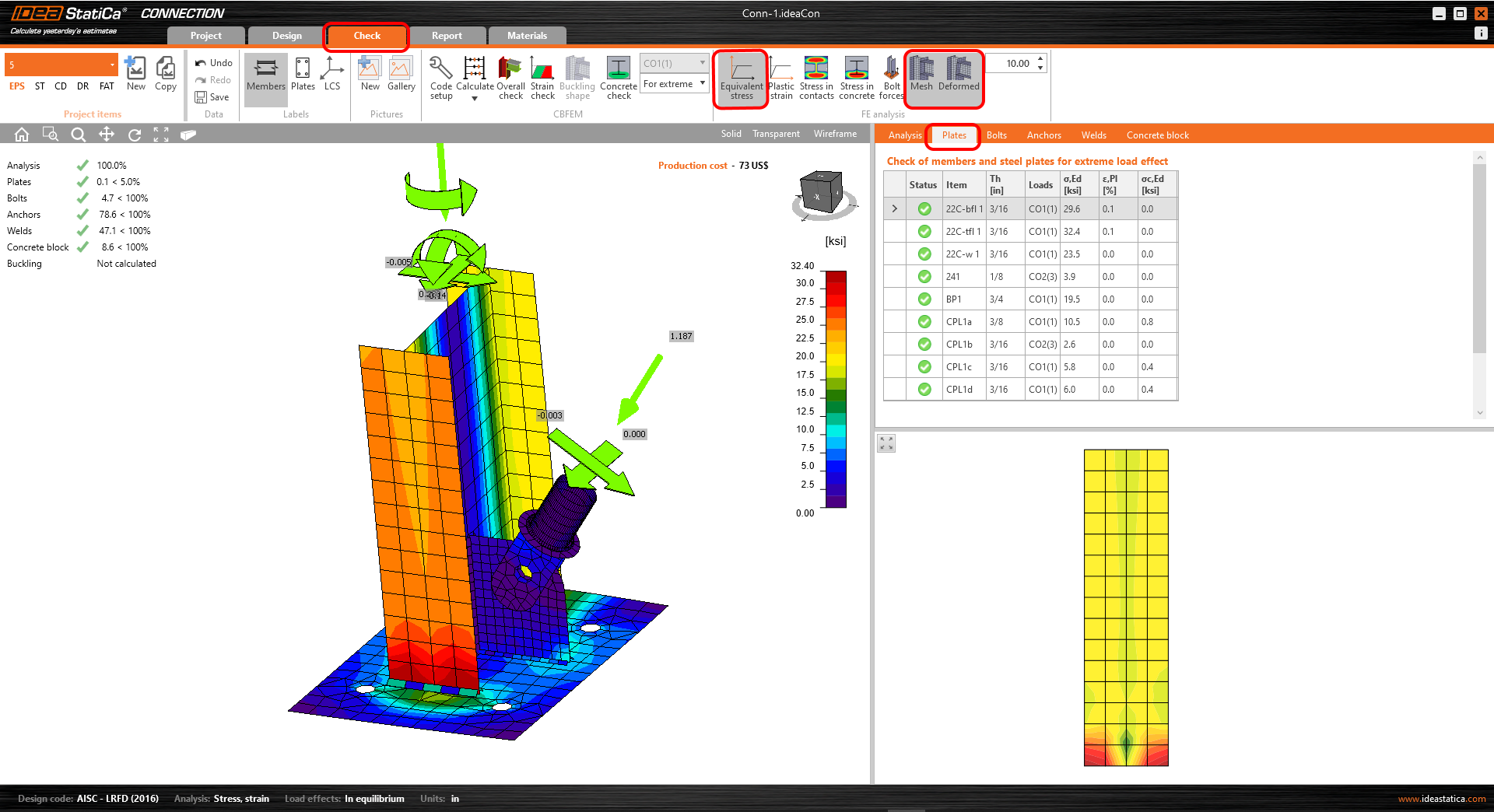
Les résultats détaillés pour les plaques, les boulons, les soudures et les ancrages peuvent être affichés via le menu du ruban. Dans l'image ci-dessous, la forme Déformée avec la Contrainte équivalente est affichée.
Vous pouvez également consulter les résultats relatifs aux ancrages.

Une fois la vérification normative terminée, vous pouvez créer le rapport contenant les résultats et les diagrammes de votre modèle d'assemblage dans l'onglet Rapport.

IDEA StatiCa propose un rapport entièrement personnalisable à imprimer ou à enregistrer dans un format modifiable. Pour plus d'informations, veuillez consulter cette page.
Enregistrez et quittez cet assemblage pour revenir à Checkbot.
Dans Checkbot, vous verrez une coche verte à côté de l'assemblage. Cela signifie que l'assemblage est valide et a satisfait à toutes les vérifications normatives. Dans le panneau Assemblage, vous pouvez également voir une représentation de l'assemblage ainsi qu'un récapitulatif des résultats de la vérification normative.
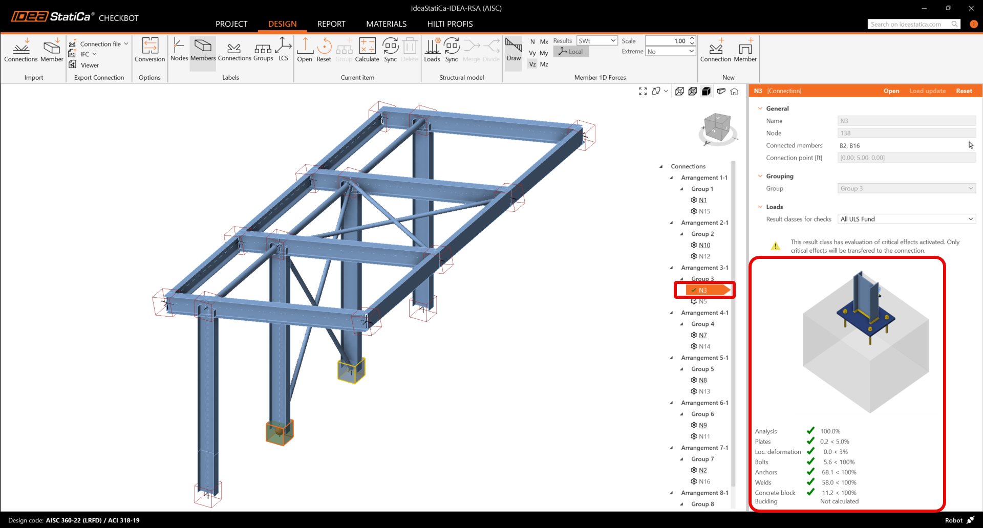
Si plusieurs assemblages similaires sont présents dans Checkbot, ils seront automatiquement regroupés. Les utilisateurs ont alors la possibilité de calculer en lot les assemblages groupés.
Dans l'exemple ci-dessous, vous pouvez voir que les deux assemblages avec platine de base, sous le groupe 3, ont satisfait à leurs vérifications normatives respectives, tandis que les assemblages restants n'ont pas encore été validés.
Synchronisation du modèle
De temps en temps, il y a des modifications de votre modèle MEF/BIM, par exemple une taille différente de section d'un élément ou des charges différentes. Il est possible de les synchroniser entre Checkbot et le modèle MEF/BIM.
Il y a deux alternatives :
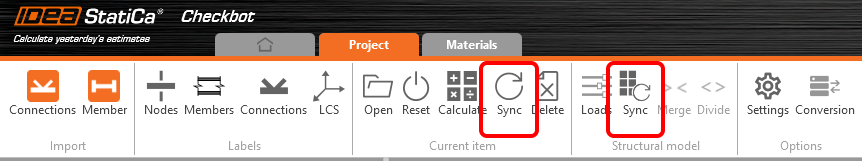
- Synchroniser l'Élément actuel (si un ou plusieurs assemblages sont sélectionnés)
- Synchroniser le Modèle structural importé entier
Pour vérifier cette fonction, vous pouvez changer la taille ou forme de section d'un élément dans votre application BIM/MEF ou modifier un cas ou combinaison de charge, etc. : changez les poteaux pour une section plus petite. N'oubliez pas de réanalyser le modèle MEF.
Dans Checkbot, sélectionnez les attaches conçues (il peut y avoir plus qu'une) et puis Synchronisation au panneau Élément actuel.
Le projet dans Checkbot sera actualisé, la conception d'attache sera enregistrée mais les résultats ne seront plus valides. Vous pouvez voir que le poteau est actualisé – avec le même changement qu'au modèle MEF.
Il faut seulement vérifier les attaches en surbrillance encore une fois en sélectionnant Calculer au panneau Élément actuel. Veuillez noter que des changements plus significatifs du modèle peuvent exiger des étapes de validation supplémentaires pour les attaches affectées (comme ci-dessus).
Si les attaches ne donnent pas de résultats désirés, vous pouvez les rouvrir pour optimiser la conception (renforcer-les si elles échouent la vérification ou alléger si l'utilisation est trop basse).
Vous avez réussi à lier SAP2000 avec IDEA StatiCa Connection via Checkbot.