Différentes façons de définir les effets de charge
Pour définir les charges, vous pouvez utiliser l'une de ces cinq options :
- Saisie manuelle dans le tableau
- Saisie manuelle depuis un tableur
- Importation automatique via le lien BIM (IDEA StatiCa Checkbot)
- Transfert de charge d'un projet Connection vers un autre
- Charge en pourcentage de la capacité de la section transversale
Examinons maintenant chacune des options de la liste.
1. Saisie manuelle dans le tableau
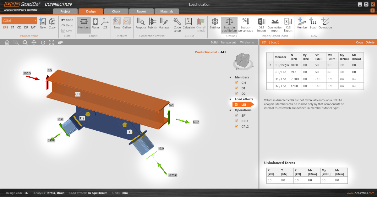
Il s'agit de la procédure de base et directe : dans le tableau des charges, vous pouvez charger les éléments par un ensemble de six efforts internes.
En fonction de l'option « Charges en équilibre » sélectionnée, le tableau des forces non équilibrées s'affiche en bas. (Remarque : lorsque l'option est désactivée, vous ne pouvez pas appliquer de charge sur l'élément appuyé. Pour en savoir plus, consultez Équilibre et élément d'appui.)
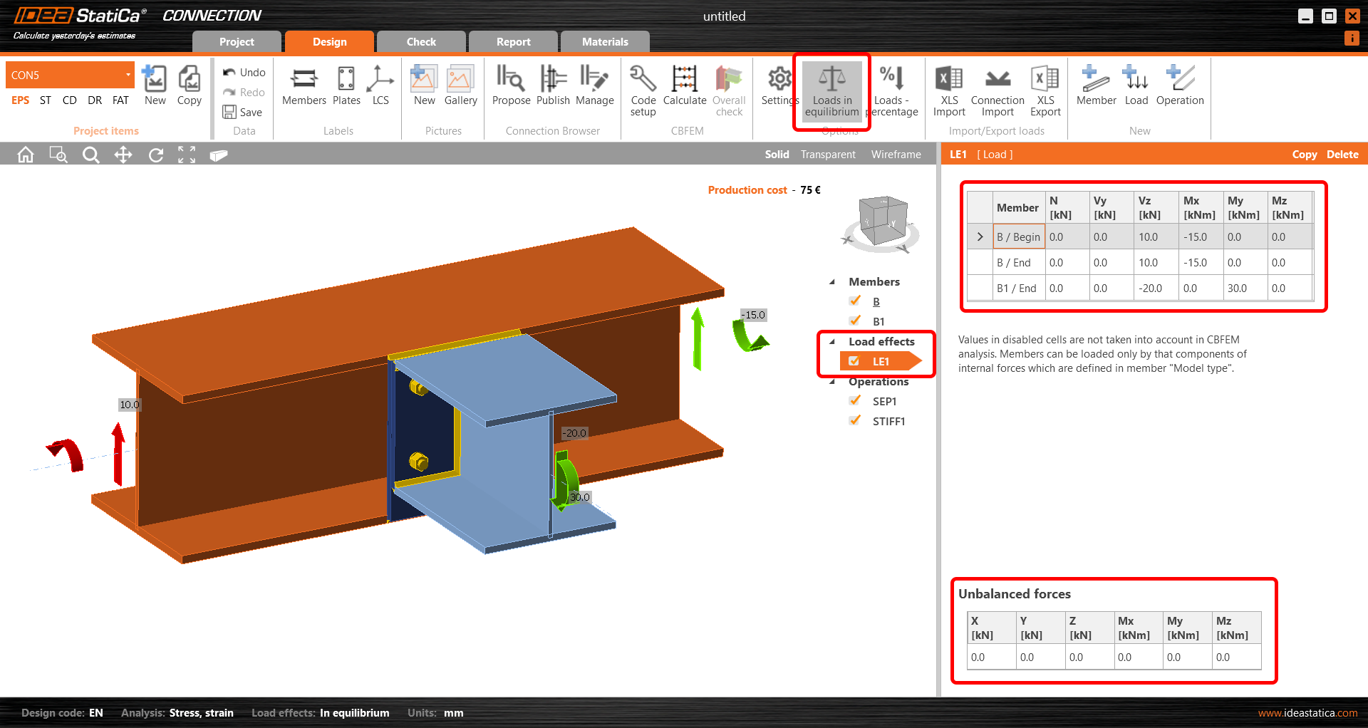
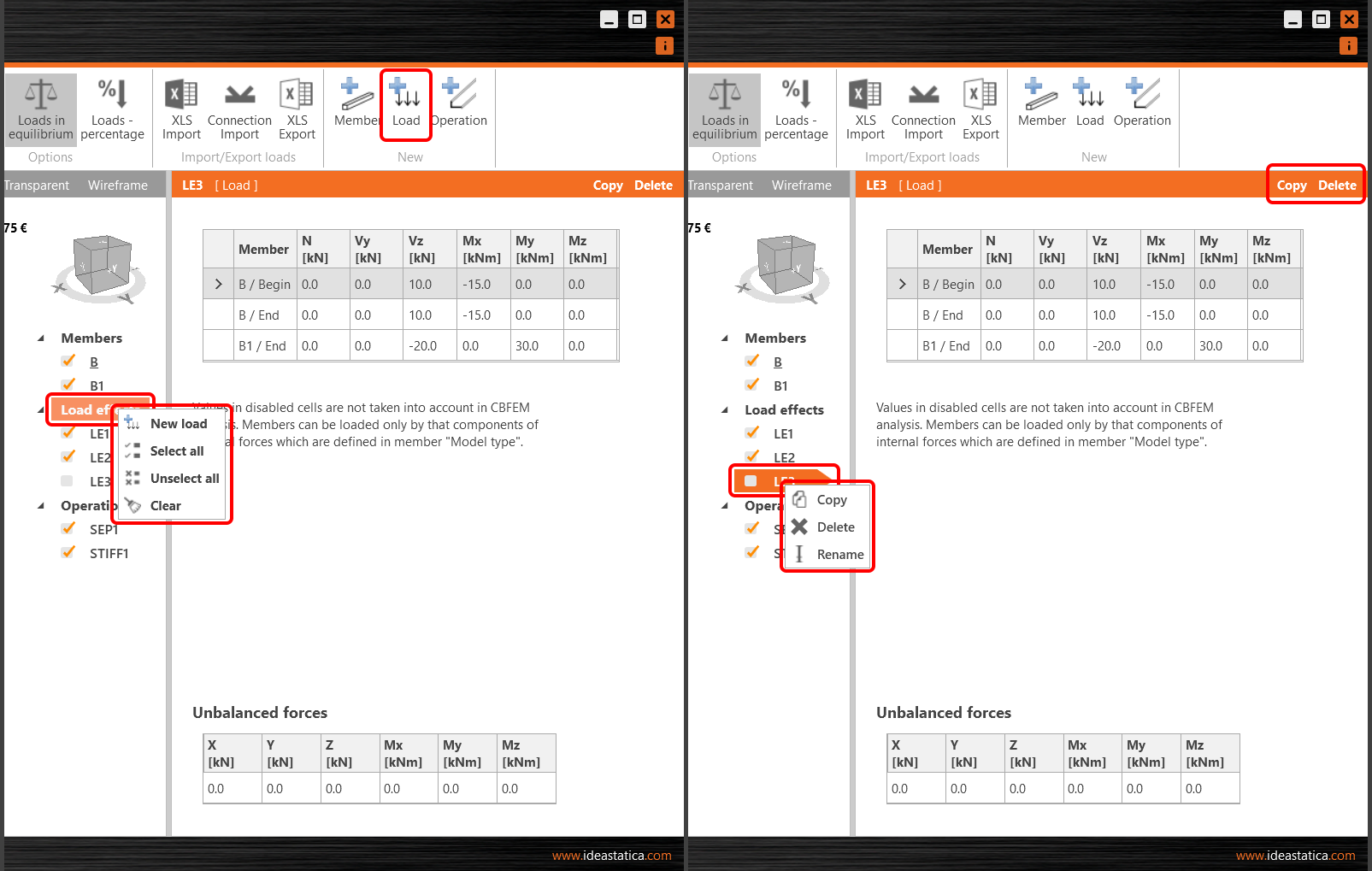
Différentes actions sont disponibles dans le ruban supérieur, au-dessus du tableau des charges, ou dans le menu contextuel (clic droit). Vous pouvez définir plusieurs cas de charge, copier ou supprimer les cas existants, ou désélectionner certains cas de charge pour l'analyse (ceux-ci ne seront pas évalués).
Pour afficher le diagramme du moment fléchissant sur l'élément sélectionné, passez en mode d'affichage Filaire (coin supérieur droit de la scène 3D) et sélectionnez l'élément dans le tableau des charges. La charge en rouge dans la scène représente la charge à l'appui (réactions).

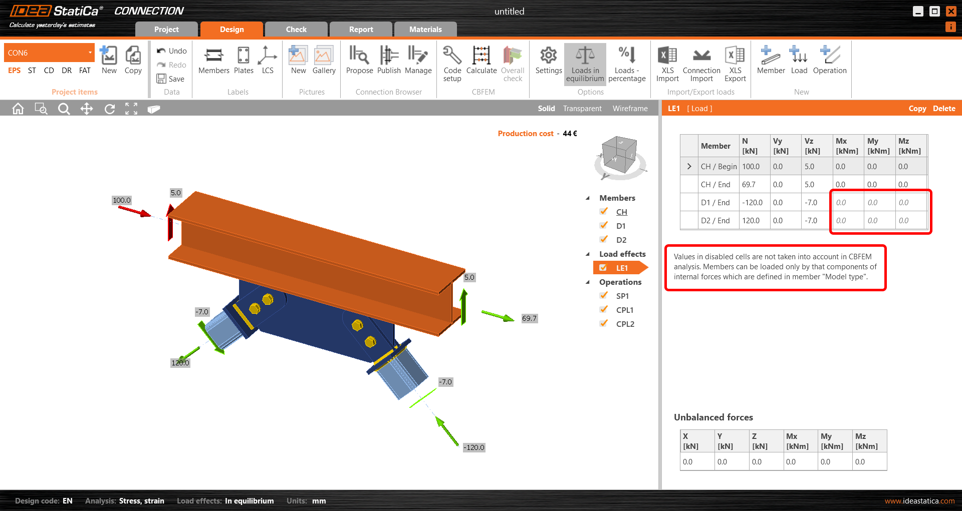
En fonction du type de modèle sélectionné, les cellules correspondantes du tableau des charges sont « verrouillées » (empêchant la saisie). Voir plus dans l'article Comment modéliser un assemblage à un boulon (Type de modèle).
Pour changer les unités, consultez Comment changer les unités dans IDEA StatiCa Connection.
Assurez-vous de définir les forces à la bonne position en tenant compte des types de modèles des éléments correspondants. Lisez l'article Comment définir la position correcte des charges (Forces dans) pour comprendre le problème.
2. Saisie manuelle depuis un tableur
Pour gagner du temps ou transférer les charges depuis un autre fichier source (il peut s'agir de votre modèle d'analyse globale ou simplement d'un autre modèle IDEA StatiCa Connection), il est possible de saisir en masse les valeurs de charge du tableau depuis un tableur. Utilisez le bouton Import XLS dans le ruban supérieur.

Dans la figure, le tableau Excel comprend trois cas de charge. Il suffit de copier + coller les valeurs (CTRL+C et CTRL+V).

Les valeurs sont automatiquement réparties en trois cas de charge. Assurez-vous que l'ordre des lignes que vous transférez correspond exactement à l'ordre des éléments dans le tableau des charges de l'assemblage. Vous pouvez réorganiser le tableau à l'aide des flèches situées à droite. Pour éviter le premier cas de charge vide, utilisez l'option Remplacer les charges existantes.
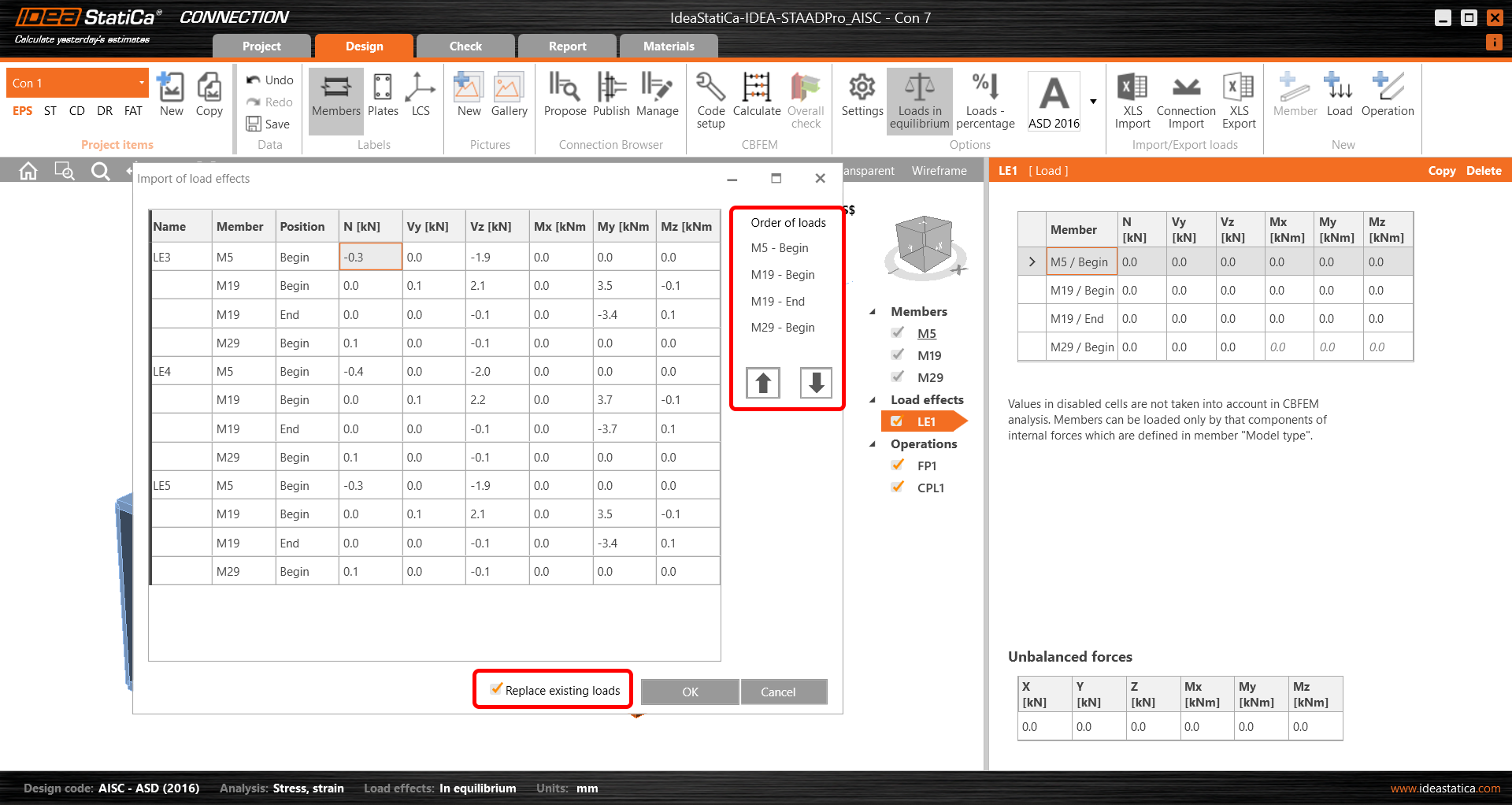
Une fois que vous confirmez par OK, trois cas de charge sont créés. Les valeurs nulles dans le tableau des forces non équilibrées confirment que l'importation a été effectuée correctement. Voir aussi Comment importer les effets de charge depuis une feuille Excel.
Pour un grand nombre d'effets de charge, envisagez d'utiliser la fonction Sélection des charges extrêmes.

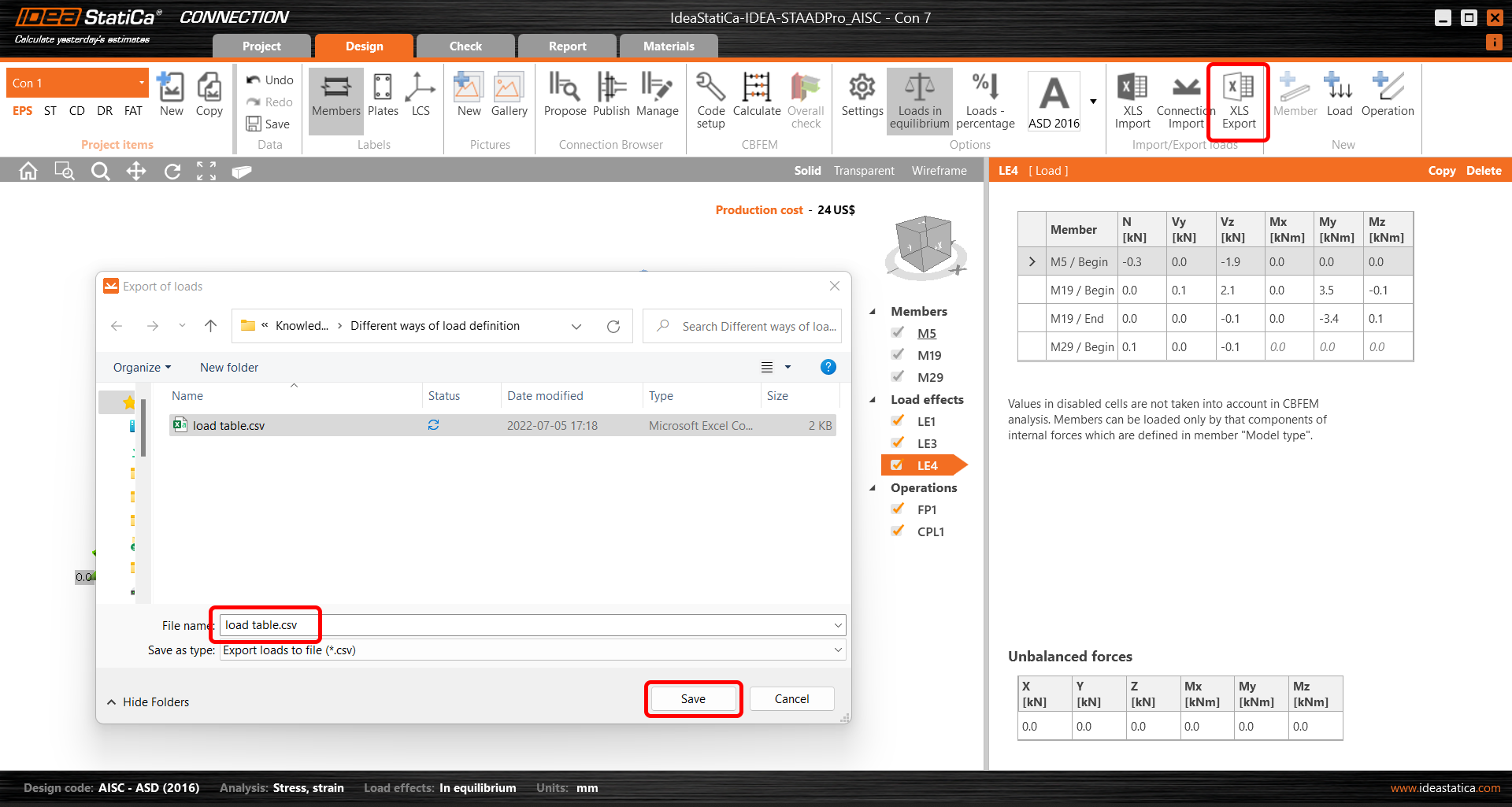
Pour transférer les charges d'un modèle IDEA StatiCa Connection vers un autre, vous pouvez également exporter les valeurs dans un tableau à l'aide du bouton Export XLS dans le ruban supérieur. Les effets de charge sont enregistrés sous forme de fichier CSV. Néanmoins, il existe également une méthode plus simple décrite à la section 4 (Transfert de charge d'un projet Connection vers un autre).
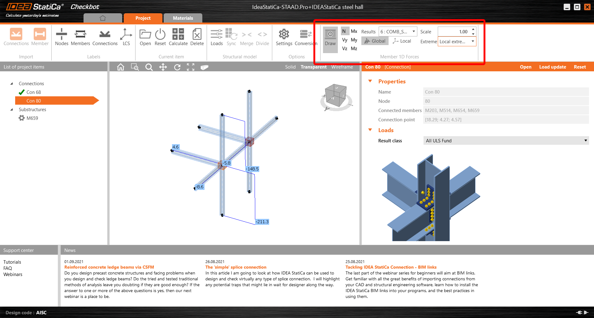
3. Importation automatique via le lien BIM (IDEA StatiCa Checkbot)
Le flux de travail BIM est la fonctionnalité essentielle d'IDEA StatiCa Connection. En utilisant le lien BIM, les efforts internes de toutes les combinaisons de charges et cas de charge sont importés en une seule fois. Pour faciliter et fluidifier le transfert non seulement des charges, mais aussi de tous les éléments et sections transversales, nous avons développé IDEA StatiCa Checkbot, une application permettant à IDEA StatiCa Connection de s'intégrer de manière transparente dans le processus BIM global.
Veuillez consulter la fonctionnalité complète d'IDEA StatiCa Checkbot dans l'article dédié ou apprenez à l'utiliser avec votre application MEF/CAO dans l'un de nos nombreux tutoriels.
Si vous n'êtes pas sûr que nous soyons connectés à l'application avec laquelle vous travaillez, veuillez visiter notre site Intégrations prises en charge. Lisez également davantage sur ce sujet dans le billet de blog BIM – La réponse à toutes nos prières (en ingénierie structurelle) ?.
Les forces non équilibrées lors de l'importation des charges via le lien BIM sont abordées dans l'article Forces non équilibrées lors de l'importation via le lien BIM.
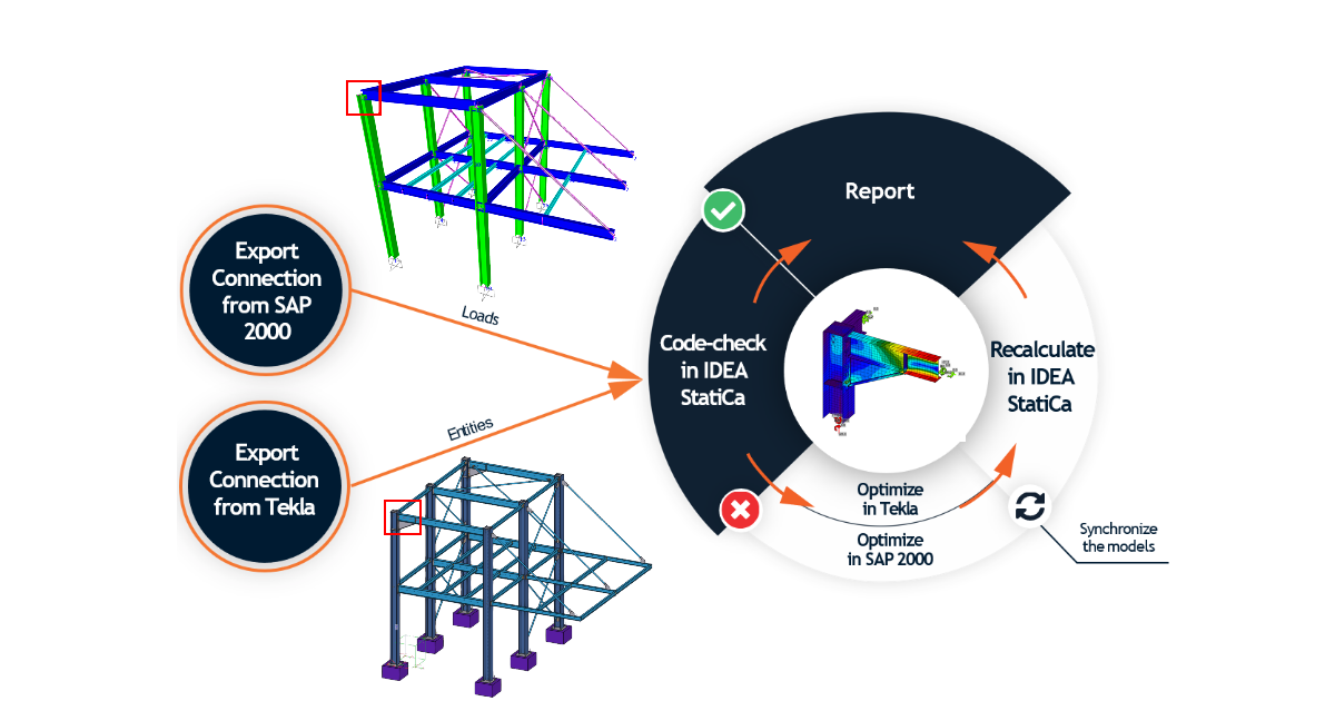
4. Transfert de charge d'un projet Connection vers un autre
Il s'agit d'une autre option pour transférer les charges d'un modèle IDEA StatiCa Connection vers un autre. Cela peut être utile, notamment lorsque vous disposez d'un modèle CAO avec des assemblages conçus et d'un modèle structurel dans un programme MEF. Dans ce cas, vous pouvez fusionner les charges du modèle d'assemblage exporté depuis le MEF avec votre modèle d'assemblage exporté depuis le CAO, et vous êtes prêt à lancer l'analyse.
Appuyez sur le bouton Import d'assemblage dans le ruban supérieur.
Sélectionnez ensuite le fichier .ideacon depuis lequel vous souhaitez importer les charges.

Tous les cas de charge sont transférés vers votre nouveau modèle d'assemblage.

Consultez l'enregistrement de notre webinaire Maîtriser IDEA StatiCa Connection - Liens BIM, où le transfert de charge d'un fichier .ideacon vers un autre via la fonction Import d'assemblage est expliqué pour combiner les modèles Tekla et SAP2000.
Le flux de travail combiné est également décrit dans notre tutoriel Comment combiner Tekla Structures et SAP2000.
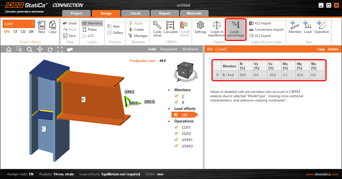
5. Charge en pourcentage de la capacité de la section transversale
Il s'agit d'une option simple pour saisir les effets de charge : les éléments peuvent être chargés par un pourcentage défini de la capacité de leur section transversale. Le paramétrage des charges en pourcentage de la capacité de la section transversale est principalement conçu comme un outil simple. Le paramétrage des charges en équilibre est préférable.
Pour en savoir plus sur cette fonctionnalité, consultez l'article dédié Chargement en pourcentage.