Introduction générale à la conception structurelle des assemblages acier
Introduction
Les ingénieurs préfèrent les éléments barres pour la conception des structures acier. Cependant, il existe de nombreux endroits sur la structure où la théorie des éléments barres n'est pas valable, par exemple : les assemblages soudés, les assemblages boulonnés, les fondations, les ouvertures dans les voiles, la hauteur variable de la section transversale et les charges concentrées. L'analyse structurelle dans ces zones est difficile et nécessite une attention particulière. Le comportement est non linéaire et les non-linéarités doivent être prises en compte, par exemple : la plastification du matériau des plaques, le contact entre les platines d'extrémité ou la platine de base et le massif en béton, les actions unilatérales des boulons et des ancrages, les soudures. Les codes de calcul, par exemple EN1993-1-8, ainsi que la littérature technique proposent des méthodes de calcul adaptées. Leur caractéristique commune est d'être dérivées pour des géométries structurelles typiques et des chargements simples. La méthode des composants est très souvent utilisée.
Méthode des composants
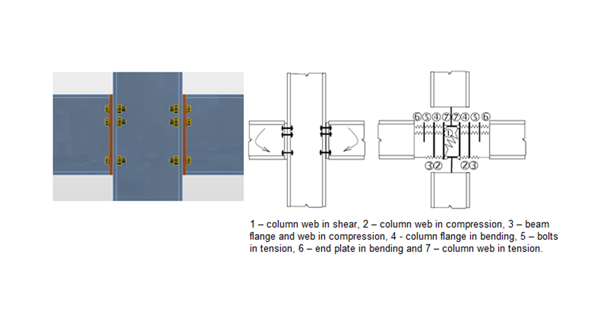
La méthode des composants (MC) traite l'assemblage comme un système d'éléments interconnectés – les composants. Le modèle correspondant est construit pour chaque type d'assemblage afin de pouvoir déterminer les efforts et les contraintes dans chaque composant – voir la figure suivante.
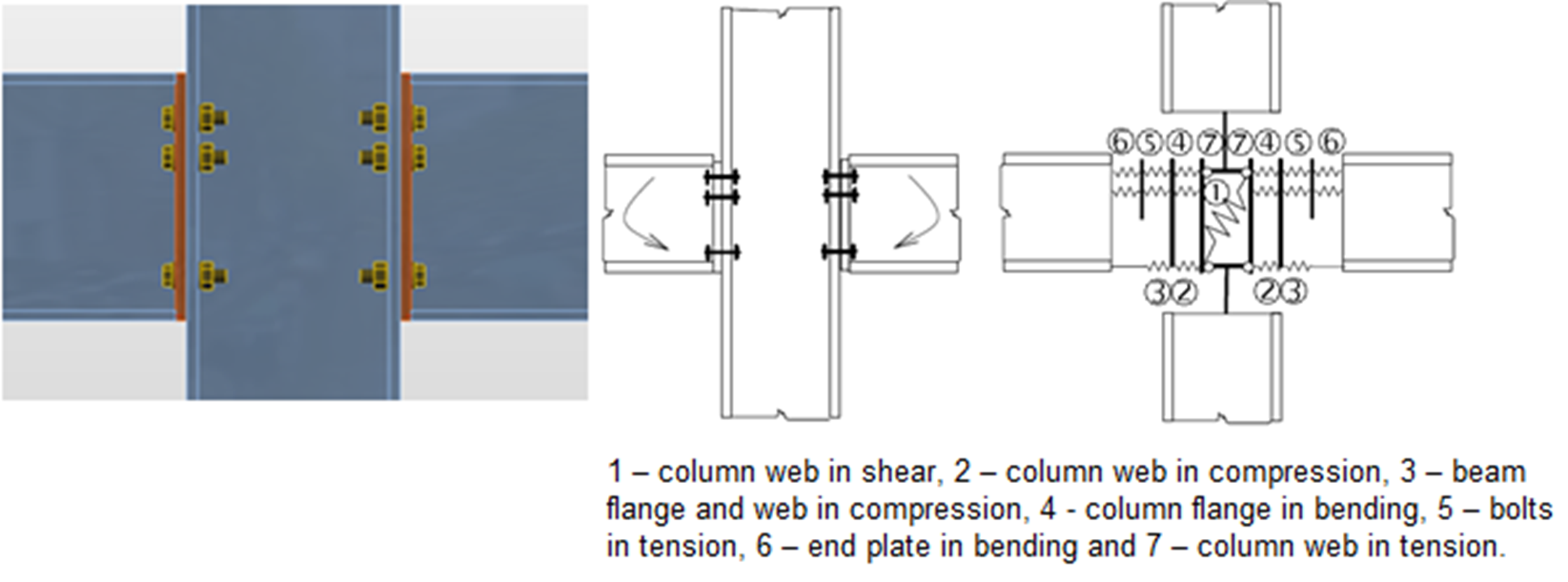
Les composants d'un assemblage avec platines d'extrémité boulonnées modélisés par des ressorts
Chaque composant est vérifié séparément à l'aide des formules correspondantes. Comme un modèle approprié doit être créé pour chaque type d'assemblage, l'utilisation de la méthode est limitée pour le calcul des assemblages de géométries générales et sous chargements généraux.
IDEA StatiCa, en collaboration avec une équipe de projet du Département des Structures en Acier et en Bois de la Faculté de Génie Civil de Prague et de l'Institut des Structures Métalliques et en Bois de la Faculté de Génie Civil de l'Université Technologique de Brno, a développé une méthode pour la conception avancée des assemblages structurels acier.
Component Based Finite Element Model (CBFEM) est une méthode :
- Suffisamment générale pour être applicable à la plupart des assemblages, fondations et détails rencontrés dans la pratique de l'ingénierie.
- Suffisamment simple et rapide dans la pratique quotidienne pour fournir des résultats dans un temps comparable aux méthodes et outils actuels.
- Suffisamment complète pour fournir à l'ingénieur structure une information claire sur le comportement de l'assemblage, les contraintes, les déformations, les réserves des composants individuels ainsi que sur la sécurité et la fiabilité globales.
La méthode CBFEM repose sur l'idée que la plupart des parties vérifiées et très utiles de la MC doivent être conservées. Le point faible de la MC – sa généralité lors de l'analyse des contraintes des composants individuels – a été remplacé par une modélisation et une analyse utilisant la Méthode des Éléments Finis (MEF).
La MEF est une méthode générale couramment utilisée pour l'analyse structurelle. L'utilisation de la MEF pour la modélisation des assemblages de toutes formes semble idéale (Virdi, 1999). L'analyse élasto-plastique est nécessaire, car l'acier plastifie habituellement dans la structure. En effet, les résultats de l'analyse linéaire sont inutilisables pour la conception des assemblages.
Les modèles MEF sont utilisés à des fins de recherche sur le comportement des assemblages ; ils font généralement appel à des éléments volumiques et à des valeurs mesurées des propriétés des matériaux.
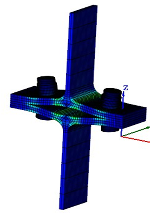
Modèle MEF d'un assemblage pour la recherche. Il utilise des éléments volumiques 3D pour les plaques et les boulons
Les âmes et les semelles des éléments assemblés sont modélisées à l'aide d'éléments coques dans le modèle CBFEM, pour lesquels une solution connue et vérifiée est disponible.
Les éléments de fixation – boulons et soudures – sont les plus délicats du point de vue du modèle d'analyse. La modélisation de tels éléments dans les logiciels MEF généraux est difficile car ces logiciels n'offrent pas les propriétés requises. Des composants MEF spéciaux ont donc dû être développés pour modéliser le comportement des soudures et des boulons dans un assemblage.
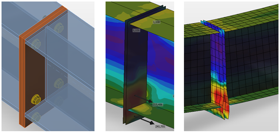
Modèle CBFEM d'un assemblage boulonné par platines d'extrémité
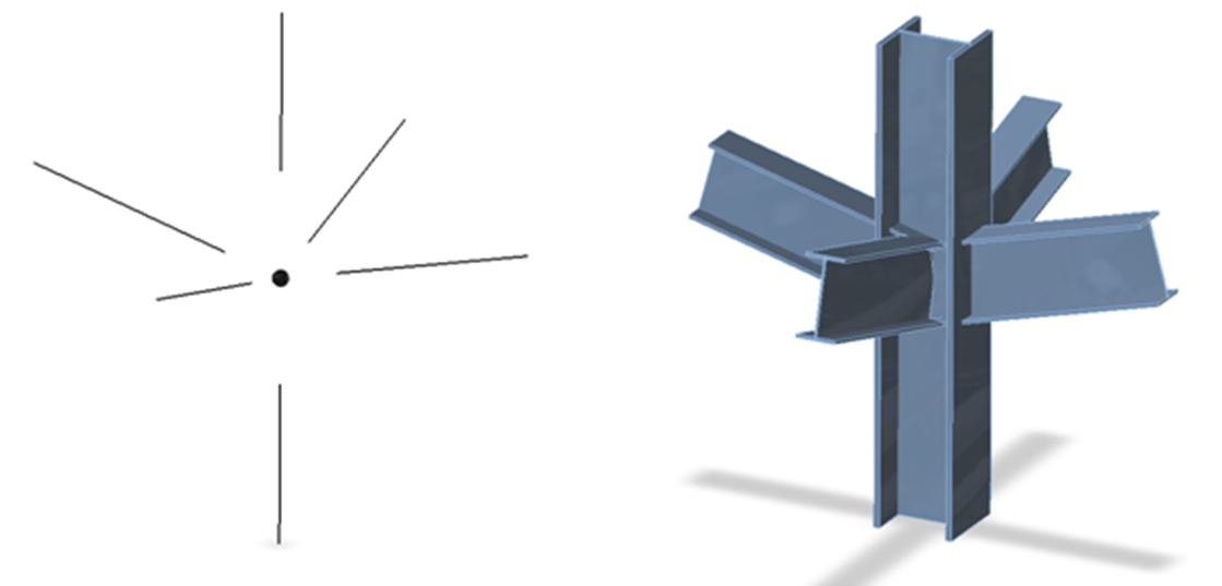
Les assemblages d'éléments sont modélisés comme des points sans masse lors de l'analyse d'une structure en portique ou en poutre acier. Les équations d'équilibre sont assemblées aux nœuds et les efforts internes aux extrémités des poutres sont déterminés après résolution de l'ensemble de la structure. En réalité, l'assemblage est chargé par ces efforts. La résultante des efforts de tous les éléments au nœud est nulle – l'ensemble de l'assemblage est en équilibre.
La géométrie réelle d'un assemblage n'est pas connue dans le modèle structurel. L'ingénieur définit uniquement si l'assemblage est supposé rigide ou articulé.
Il est nécessaire de créer un modèle fiable de l'assemblage, respectant l'état réel, pour concevoir correctement l'assemblage. Les extrémités des éléments d'une longueur égale à 2 à 3 fois la hauteur maximale de la section transversale sont utilisées dans la méthode CBFEM. Ces tronçons sont modélisés à l'aide d'éléments coques.
Un assemblage théorique (sans masse) et la géométrie réelle de l'assemblage sans extrémités d'éléments modifiées
Pour une meilleure précision du modèle CBFEM, les efforts aux extrémités des éléments 1D sont appliqués comme charges aux extrémités des tronçons. Les sextuplets d'efforts issus de l'assemblage théorique sont transférés à l'extrémité du tronçon – les valeurs des efforts sont conservées, mais les moments sont modifiés par l'action des efforts sur les bras correspondants.
Les extrémités des tronçons au niveau de l'assemblage ne sont pas connectées. La connexion doit être modélisée. Des opérations dites de fabrication sont utilisées dans la méthode CBFEM pour modéliser l'assemblage. Les opérations de fabrication comprennent notamment : les coupes, les décalages, les trous, les raidisseurs, les nervures, les platines d'extrémité et les éclisses, les cornières, les goussets et autres. Les éléments de fixation (soudures et boulons) sont également ajoutés.
IDEA StatiCa Connection peut effectuer deux types d'analyse :
- Analyse géométriquement linéaire avec non-linéarités matérielles et de contact pour l'analyse des contraintes et des déformations,
- Analyse aux valeurs propres pour déterminer la possibilité de flambement.
Dans le cas des assemblages, l'analyse géométriquement non linéaire n'est pas nécessaire sauf si les plaques sont très élancées. L'élancement des plaques peut être déterminé par une analyse aux valeurs propres (flambement). Pour l'élancement limite au-delà duquel l'analyse géométriquement linéaire reste suffisante, voir le chapitre 3.9. L'analyse géométriquement non linéaire n'est pas implémentée dans le logiciel.