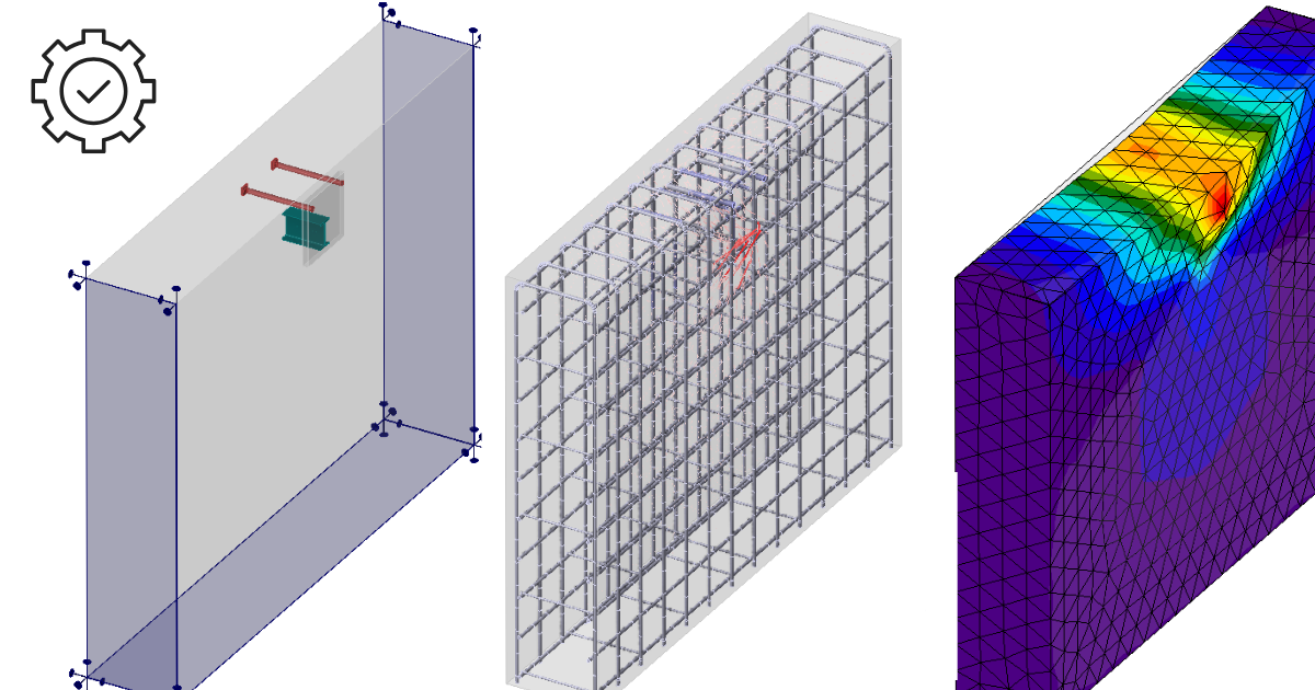
Detail 3D est essentiellement une extension de l'application Detail IDEA StatiCa établie. Il ajoute un nouveau type de modèle 3D et avec cela vient l'implémentation d'une méthode de calcul des champs de contraintes dans l'espace 3D appelée 3D CSFM. Les calculs et les vérifications sont implémentés pour l'État Limite Ultime.
Avant d'entrer dans la description des fonctionnalités de Detail 3D, il sera utile de signaler l'existence des bases théoriques, où vous pouvez lire plus de détails techniques sur les entités individuelles du modèle et les calculs eux-mêmes.
Dans la première étape, l'utilisateur peut sélectionner un nouveau type de modèle sur l'écran initial (dans l'assistant), où plusieurs modèles sont disponibles, et bien sûr, l'option de saisir un modèle de zéro.
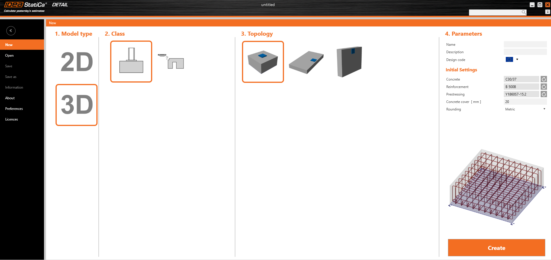
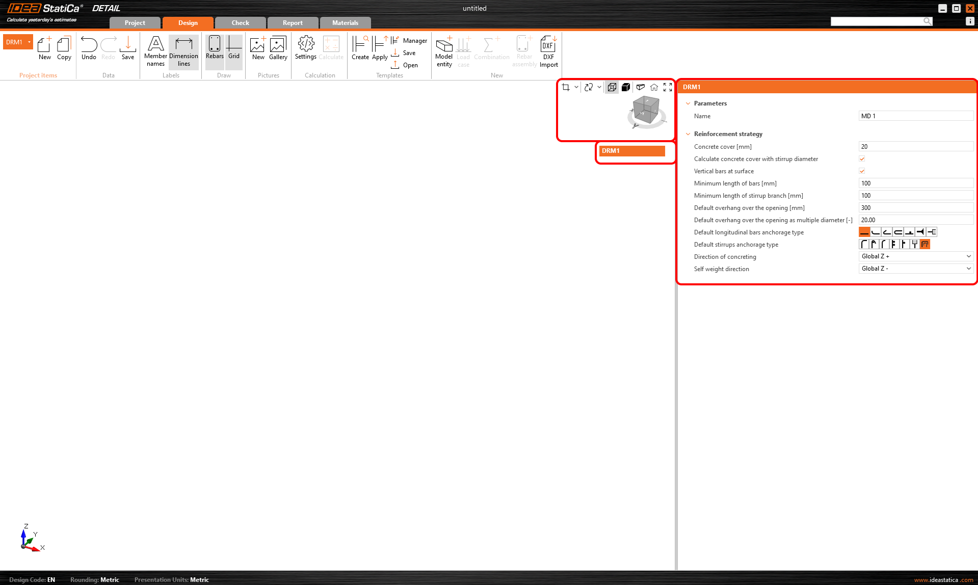
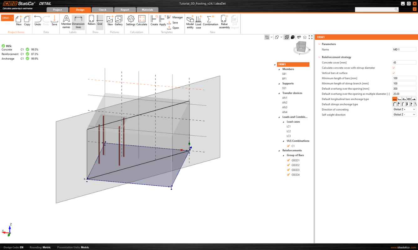
Comme pour les modèles 2D, vous pouvez modifier les paramètres initiaux dans la partie droite, tels que le code de calcul, les matériaux et l'enrobage du béton.
Après avoir créé un modèle vierge ou un modèle à partir d'un modèle, les options familières à l'environnement de modélisation 2D sont disponibles.
Les options pour travailler avec plusieurs éléments de projet se trouvent dans le ruban supérieur, ainsi que les boutons Annuler/Rétablir désormais standard, les options d'affichage des étiquettes, les contrôles de la galerie, les paramètres de calcul et les contrôles de gestion des modèles.
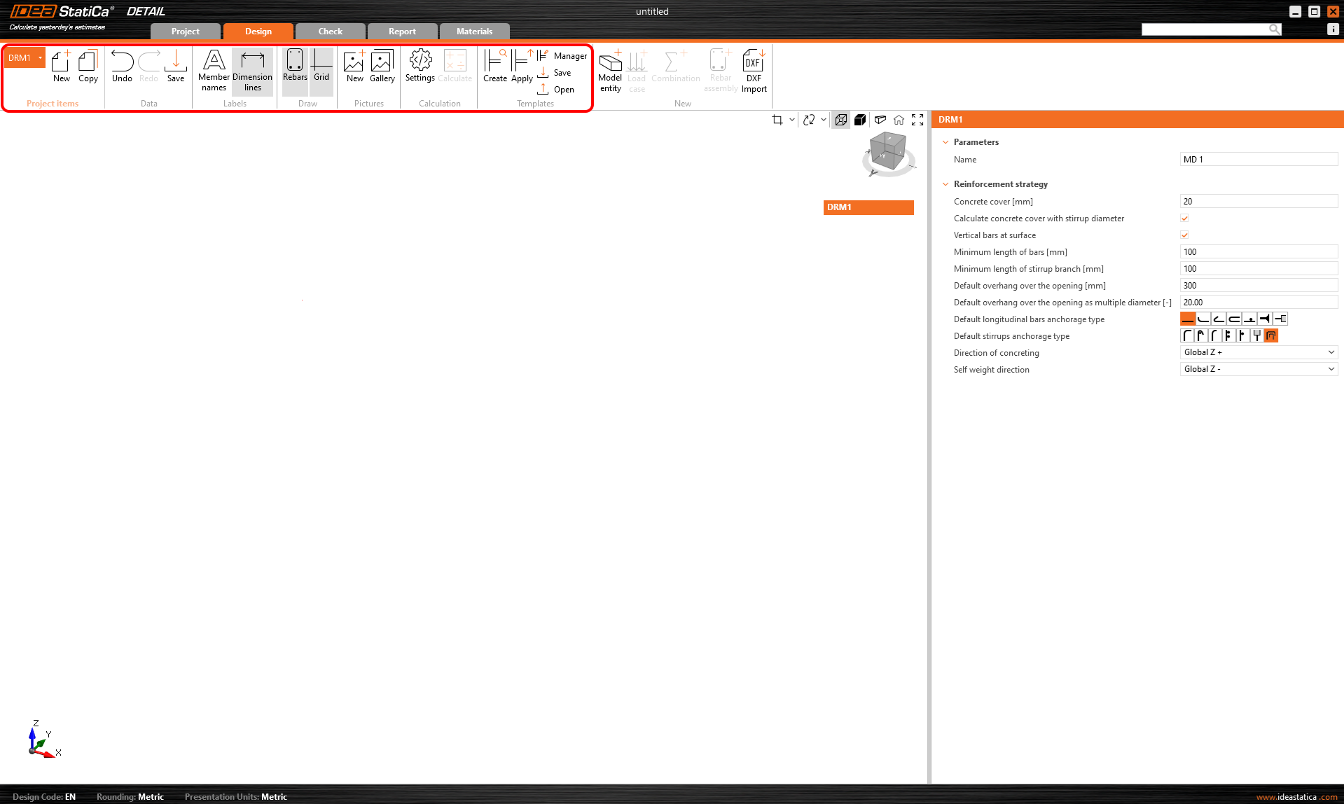
Il initialise également l'arborescence, dont le premier élément, appelé par défaut DRM1, contient les paramètres par défaut pour l'élément de projet actuel. Au-dessus de l'arborescence, vous pouvez trouver des outils pour manipuler le modèle.
Entités du modèle
Nous incluons les éléments suivants dans la catégorie d'entités du modèle dans l'application Detail :
- Membrures
- Appuis
- Dispositifs de transfert de charge
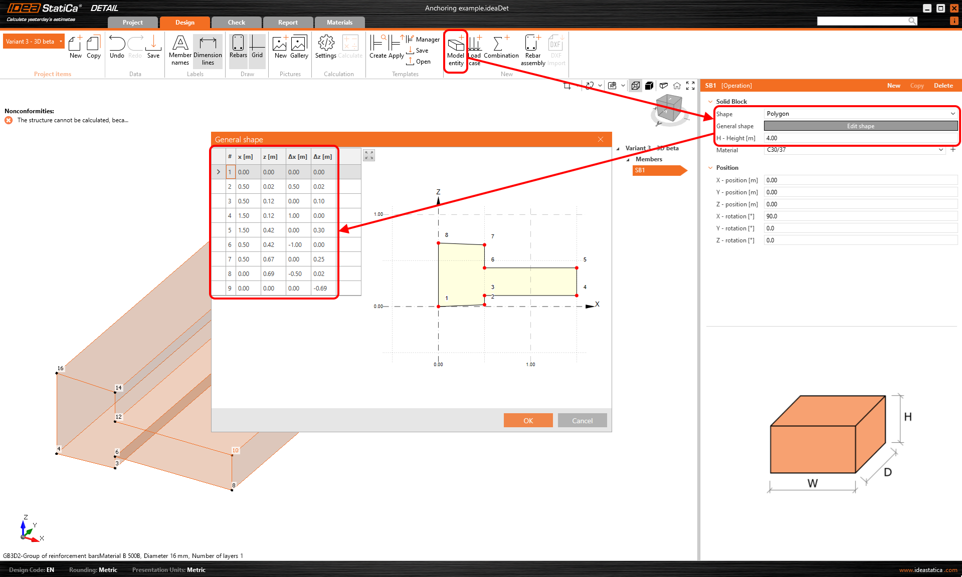
Une seule membrure peut être saisie, pouvant être définie comme une forme rectangulaire ou polygonale. Une forme rectangulaire est définie par trois dimensions, tandis que pour l'option Polygone, la forme dans l'espace 2D est saisie dans un tableau à l'aide de coordonnées, qui peuvent ensuite être extraites dans l'espace. Pour définir la forme générale d'un polygone, les coordonnées individuelles peuvent être renseignées dans le tableau, ou un copier-coller depuis un tableur (tel que Microsoft Excel) peut être utilisé.
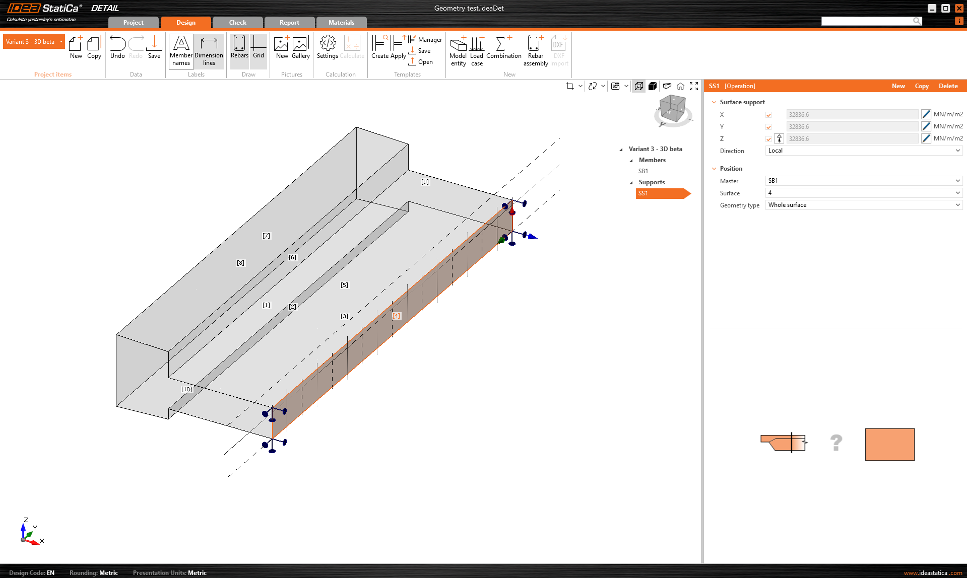
L'appui surfacique est utilisé pour supporter le modèle. Ce type d'appui peut être spécifié de deux manières - deux types de géométrie.
- Surface entière
- Polyligne
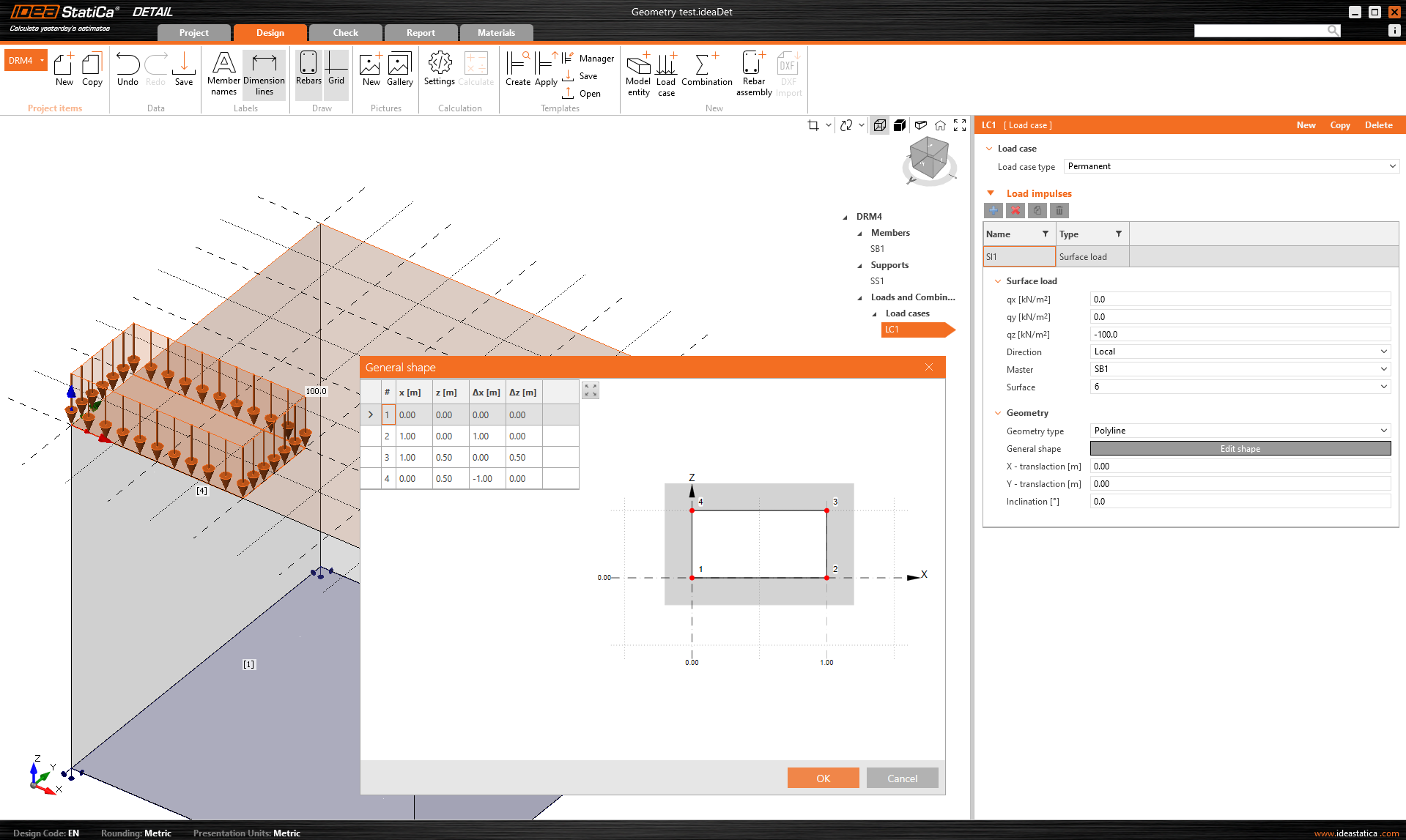
Dans les deux cas, vous devez choisir une surface de référence et bien entendu définir les degrés de liberté. L'appui peut être défini comme élastique et le type Compression uniquement peut être utilisé pour une direction perpendiculaire à la surface spécifiée. Dans la figure suivante, nous pouvons voir la saisie de l'appui sur la surface entière numéro 4 et l'option Compression uniquement désactivée.
Pour la deuxième option de saisie par polyligne, le même tableau est disponible que pour la saisie des membrures. Là encore, vous pouvez utiliser la fonctionnalité copier-coller ou saisir les coordonnées manuellement. La forme saisie peut être déplacée le long de la surface de référence à l'aide des coordonnées X et Y, ou pivotée en entrant un angle.
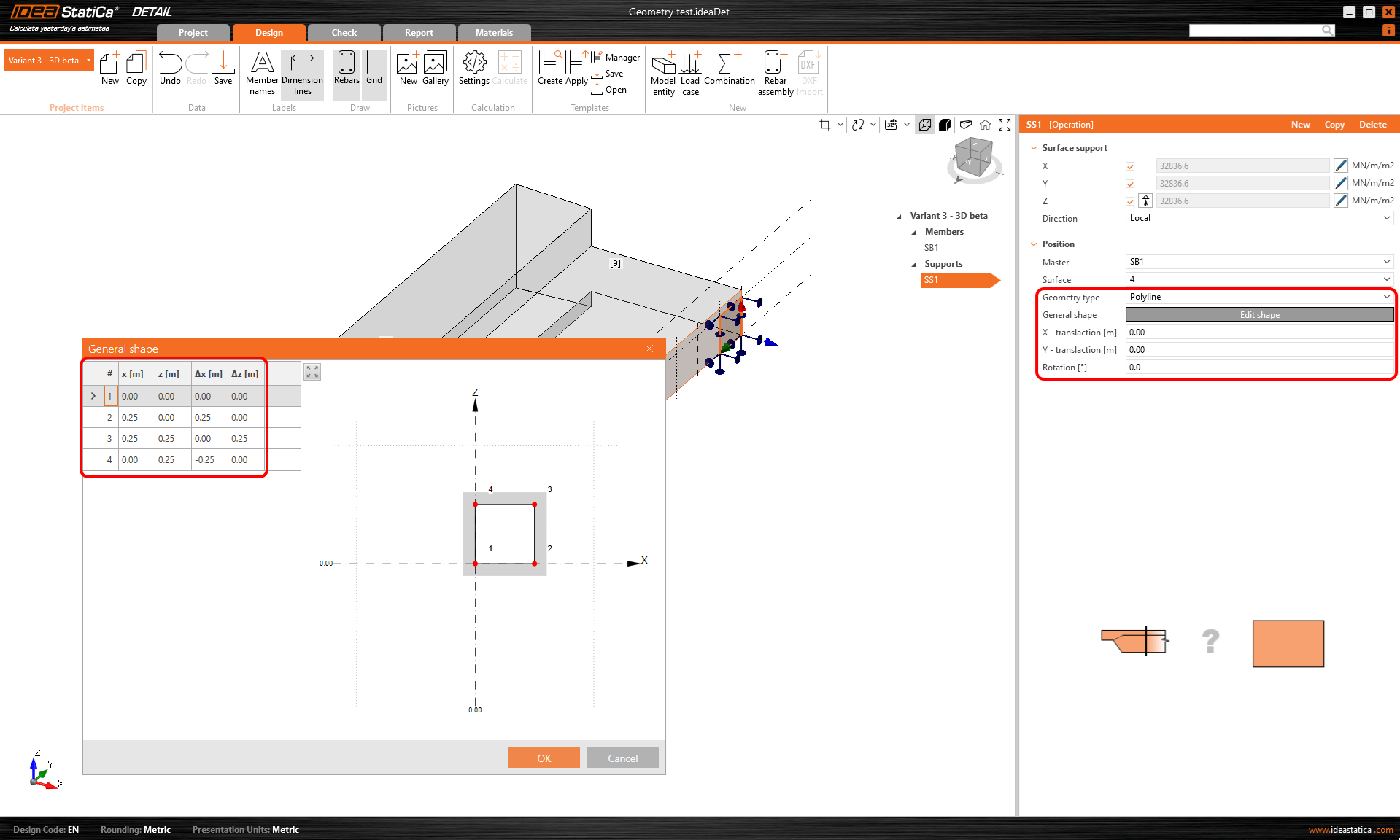
Notez qu'il est possible de définir une polyligne de sorte que l'origine des coordonnées se trouve au centre de gravité de la forme souhaitée. La position sera alors référencée par les coordonnées X et Y par rapport à ce centre de gravité.
Rigidité des appuis pour les fondations
Lors de la modélisation, nous pouvons envisager deux cas. Si nous modélisons un ancrage dans une structure, les appuis peuvent être supposés infiniment rigides.
Dans le cas d'un ancrage dans un bloc de fondation, la rigidité doit être définie correctement. De plus, les appuis doivent être définis en compression uniquement.
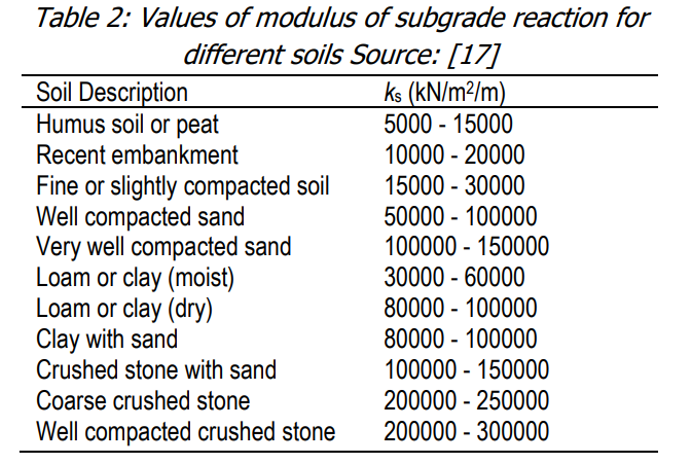
Les valeurs dans la direction z (rigidité Kz) sont tirées de la littérature selon le type de sol approprié. Un exemple spécifique peut être trouvé dans le tutoriel.
Les valeurs dépendent des recommandations de la littérature régionale pertinente. Alternativement, les valeurs sont obtenues auprès de l'ingénieur géotechnicien.
Dans les directions horizontales (Kx et Ky), la situation est moins simple. Notre recommandation générale est d'utiliser une valeur d'environ 1/10 de Kz combinée au jugement de l'ingénieur.
Une approche plus précise consisterait à utiliser une procédure itérative, à partir de laquelle nous avons dérivé notre recommandation.
Tout d'abord, définissez Kx et Ky à des valeurs très faibles (pour des raisons de calcul, il n'est pas conseillé de définir la valeur directement à zéro), par exemple 0,1, et examinez les contraintes dans les armatures.
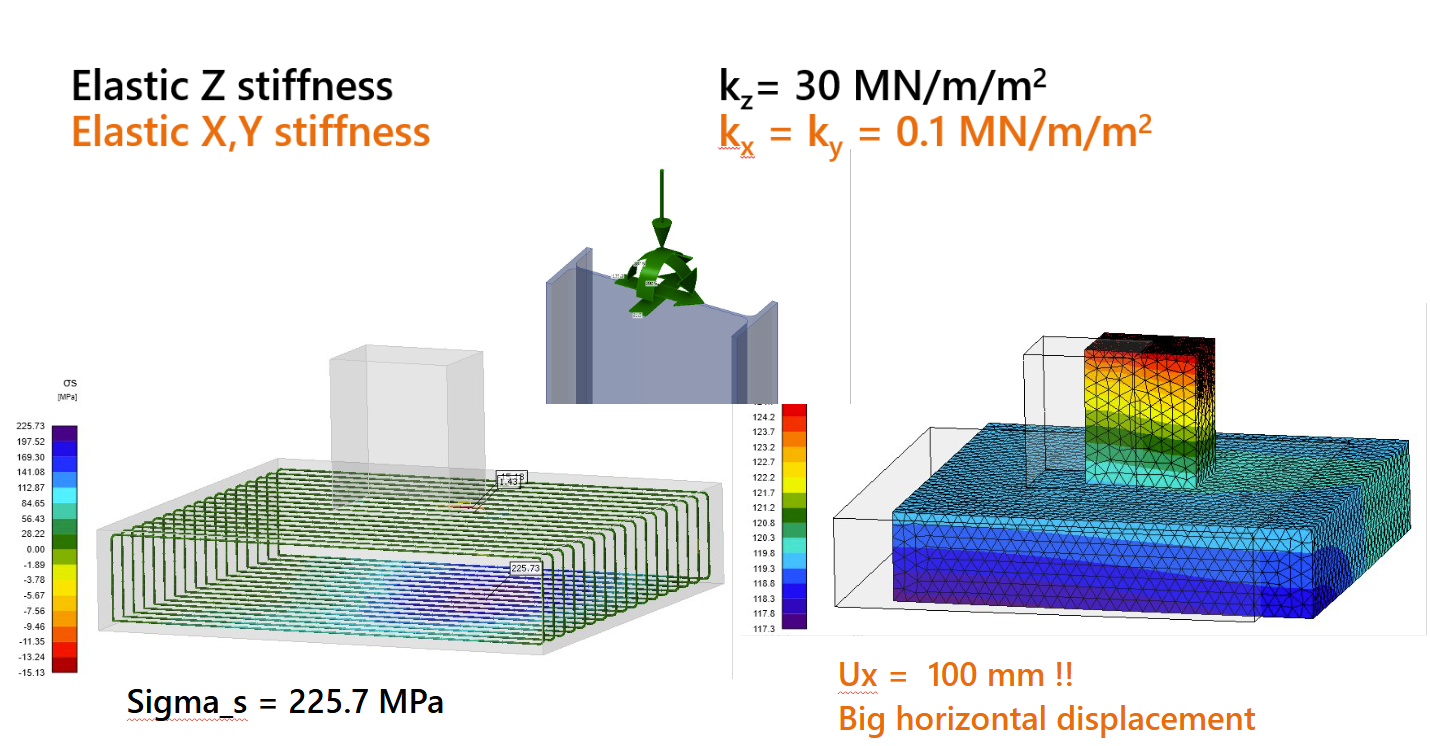
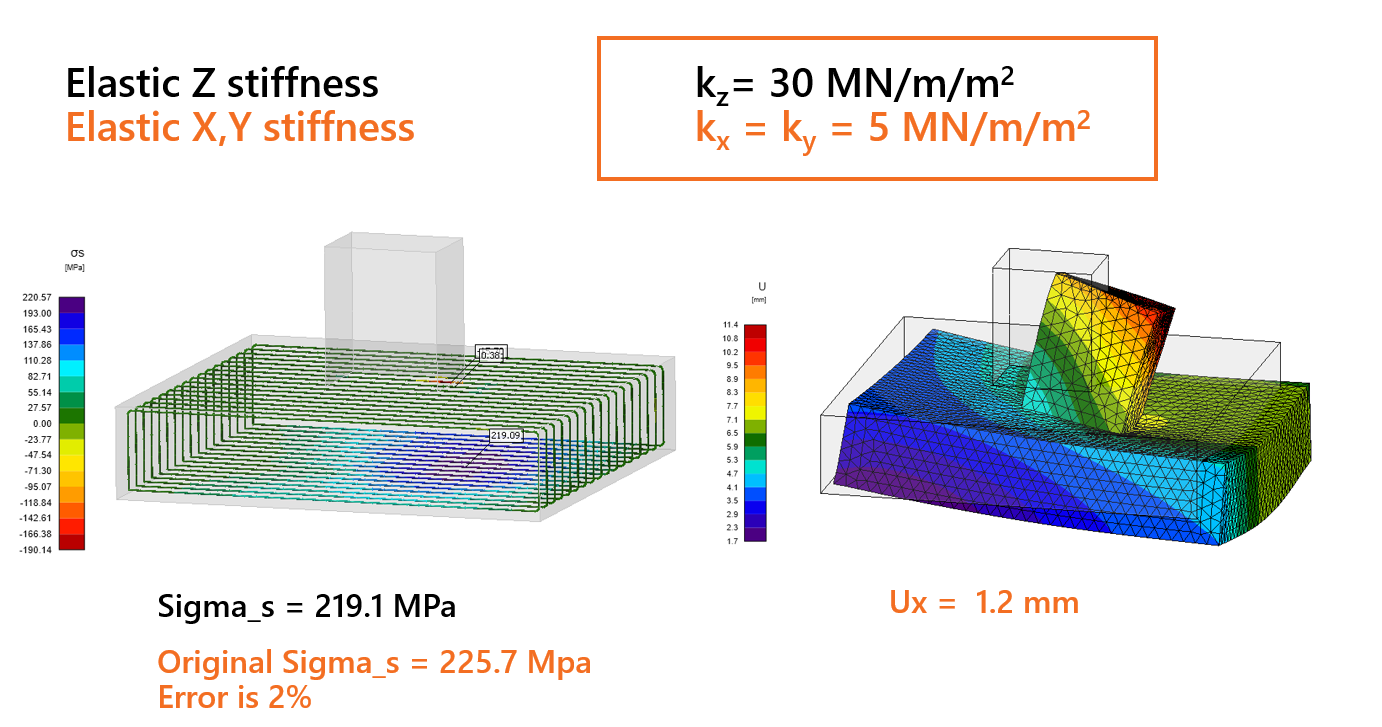
Étant donné que ces faibles valeurs entraînent des déplacements irréalistes, la rigidité doit être progressivement augmentée pour mieux refléter la réalité. L'objectif est d'obtenir des valeurs de déplacement plus réalistes tout en maintenant la contrainte de traction des armatures au bord inférieur proche de la valeur initiale, avec un écart inférieur à 5 %.
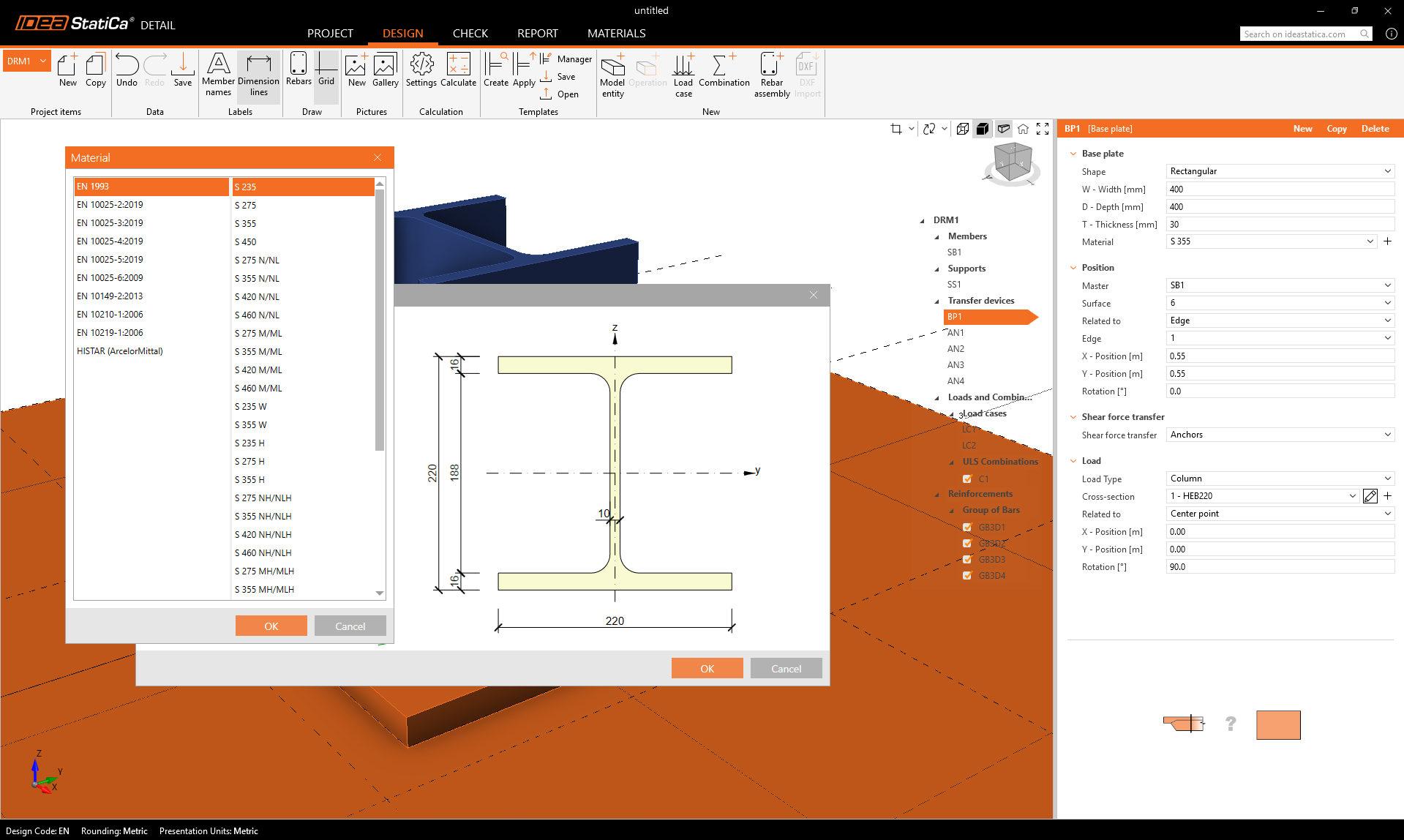
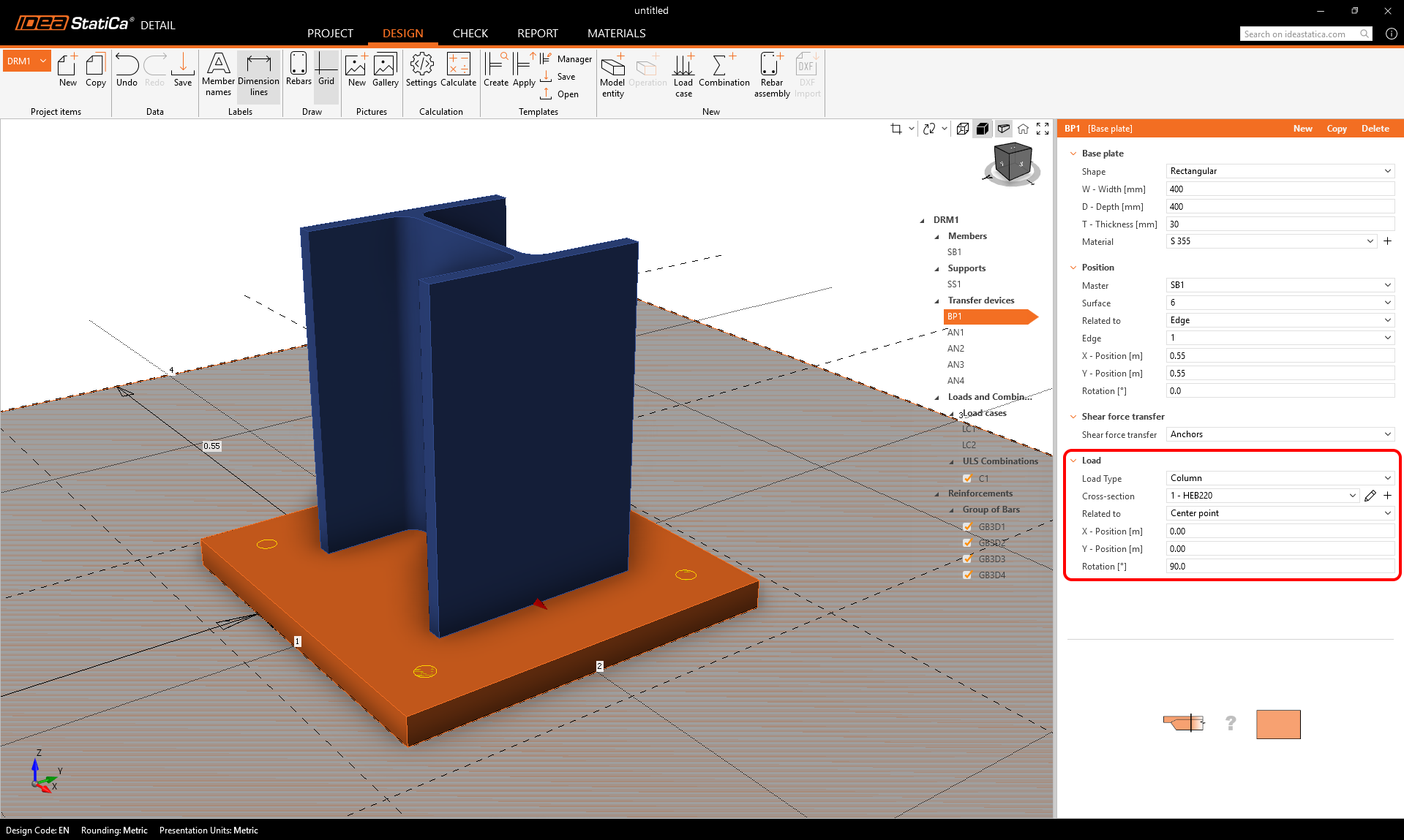
Les dispositifs de transfert de charge comprennent deux entités : la platine de base et l'ancrage individuel. Commençons par la platine de base. Pour définir la position, une surface de référence et un bord doivent être sélectionnés. Ceux-ci définissent l'origine des coordonnées à partir desquelles les distances X et Y sont mesurées. Il existe deux options de définition de forme : Rectangulaire et Polygone.
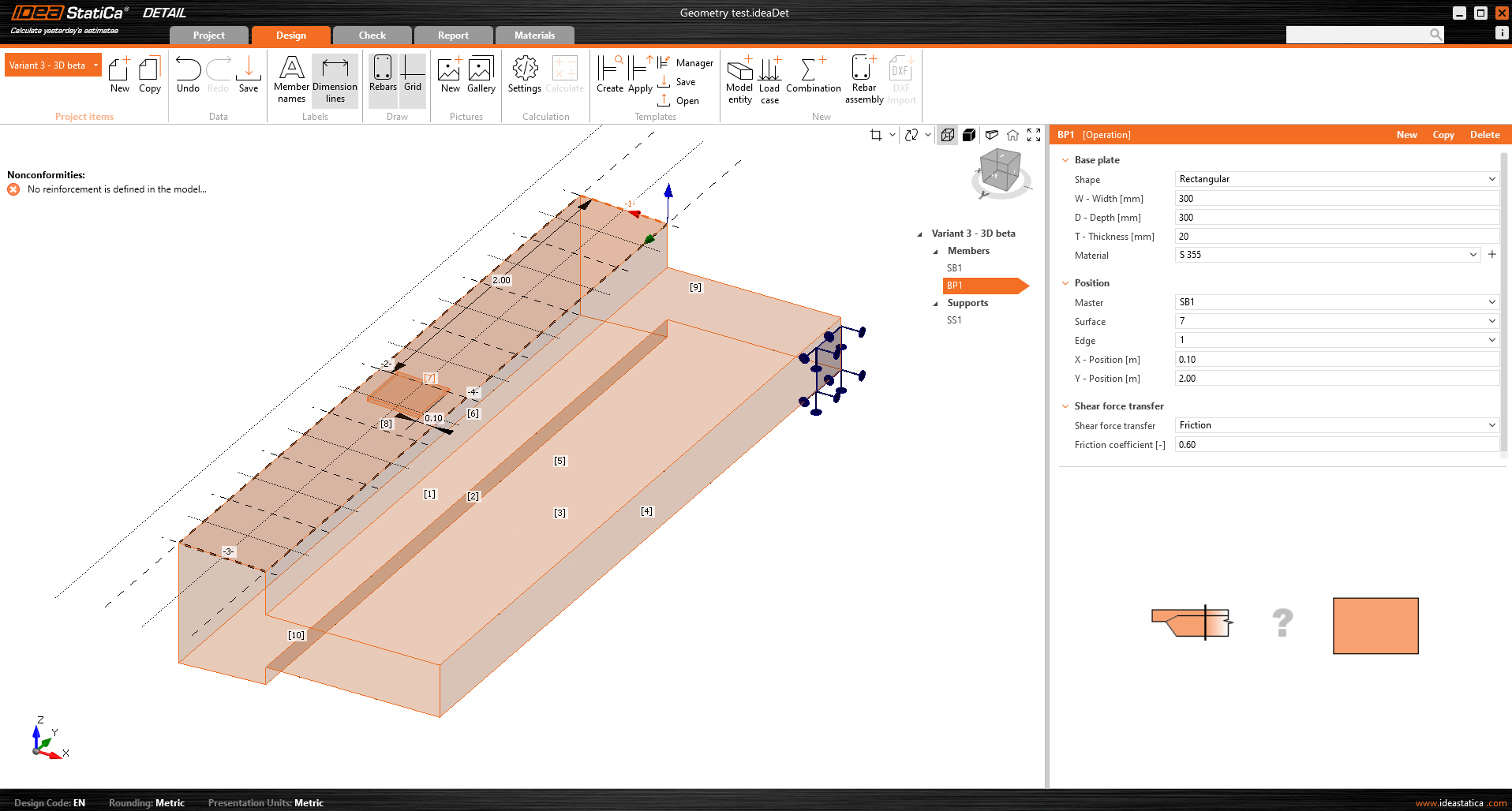
La platine de base est reliée à l'élément en béton par un contact qui transfère les contraintes de compression et, si l'utilisateur le souhaite, peut également transmettre des contraintes de cisaillement. Trois mécanismes de transfert du cisaillement peuvent être sélectionnés :
- par frottement
- par ancrages
- par bêche
Le logiciel ne permet pas de combiner ces mécanismes de transfert du cisaillement.
Pour l'option par frottement, la valeur de calcul du coefficient de frottement doit être saisie. Pour l'option par bêche, le profil métallique, y compris la géométrie et la position, doit être renseigné.
Toutes les configurations possibles de platines de base sont décrites dans l'article : Options des platines de base.
La platine de base peut transmettre soit une charge ponctuelle, soit un groupe de forces. Pour une charge ponctuelle, le modèle peut être chargé avec six efforts internes (Fx, Fy, Fz, Mx, My et Mz) en n'importe quelle position sur la platine de base. Pour un groupe de forces, les utilisateurs peuvent saisir les positions, intensités et directions des forces dans un tableau, permettant un positionnement général sur la platine de base. Il est important de mentionner que la platine de base est chargée ponctuellement et ne comporte ni raidisseur ni élément soudé sur sa face supérieure. Ainsi, pour une distribution correcte des charges, il est important d'utiliser une platine de base relativement rigide avec une épaisseur relativement importante. Une autre option consiste à utiliser un tronçon, qui résout le problème de rigidité de la platine.
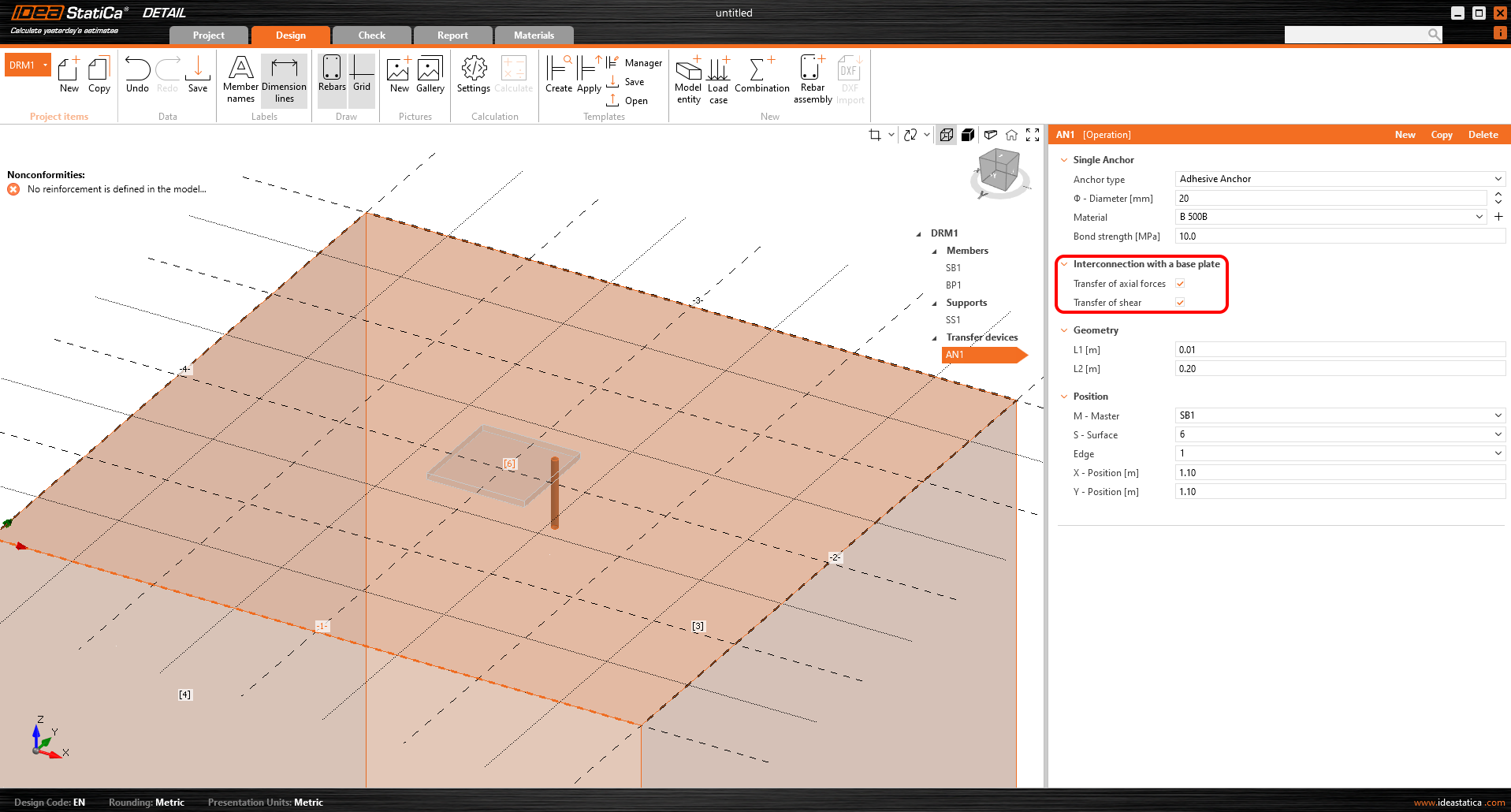
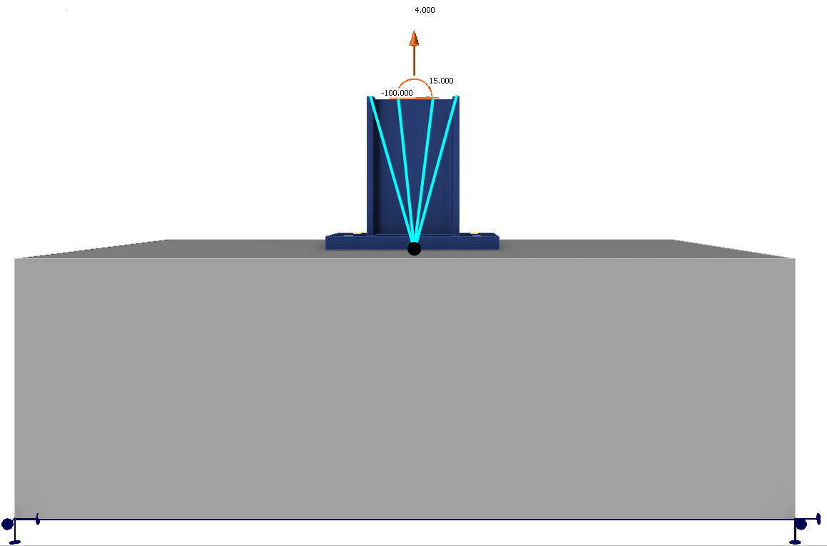
Un second dispositif de transfert de charge, l'ancrage individuel, peut être ajouté et interconnecté avec la platine de base pour créer, par exemple, une platine de base de poteau ancrée avec quatre ancrages (voir la figure ci-dessous). Il est également possible de modéliser des ancrages séparés sans platine de base.
De plus amples informations sur l'interconnexion avec la platine de base sont disponibles dans le Contexte théorique.
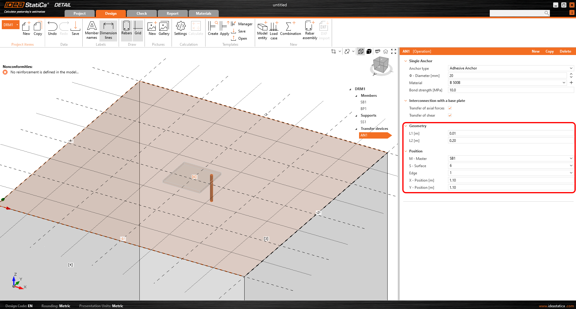
En termes de position et de géométrie, les ancrages sont référencés par rapport à la surface et au bord du bloc, y compris la détermination de la position relative comme pour la platine de base. Il est bien entendu possible de spécifier la longueur de l'ancrage dans le béton et la longueur au-dessus de la surface du béton.
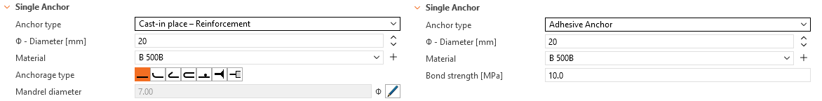
Les ancrages sont disponibles en deux variantes :
- Coulés en place
- Ancrages adhésifs
Pour le ferraillage coulé en place, la résistance d'adhérence est utilisée conformément à l'EN 1992-1-1 chap. 8.4.2. De plus, il est possible de spécifier le type d'ancrage pour ce type d'ancrage comme pour un ferraillage conventionnel.
Pour les ancrages adhésifs, il est possible de saisir directement la résistance d'adhérence, que l'utilisateur peut trouver dans la fiche technique du mortier adhésif utilisé. Notez qu'il est nécessaire de saisir la valeur de calcul de la résistance d'adhérence. L'article suivant vous aidera à trouver la valeur.
Consultez toutes les options d'ancrages dans l'article : Options d'ancrage individuel
Une description détaillée du comportement de l'interconnexion entre l'ancrage et la platine de base est présentée dans le Contexte théorique.
Chargement
Les cas de charge peuvent être définis de la même manière que pour les éléments 2D en béton armé. Cela signifie que chaque cas de charge peut se voir attribuer un type de charge permanent ou variable. Les cas de charge permanente sont d'abord appliqués au modèle et, après un calcul réussi, les cas de charge variable sont appliqués.
Type d'impulsions de charge
Un total de 4 types d'impulsions de charge peut être ajouté à chaque cas de charge.
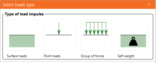
La définition des charges surfacique est identique à celle de l'appui superficiel. Cela signifie qu'il est possible de les spécifier de deux manières : Surface entière et Polyligne. Dans le cas des charges surfaciques, l'intensité de la charge est bien sûr saisie dans les trois directions générales.
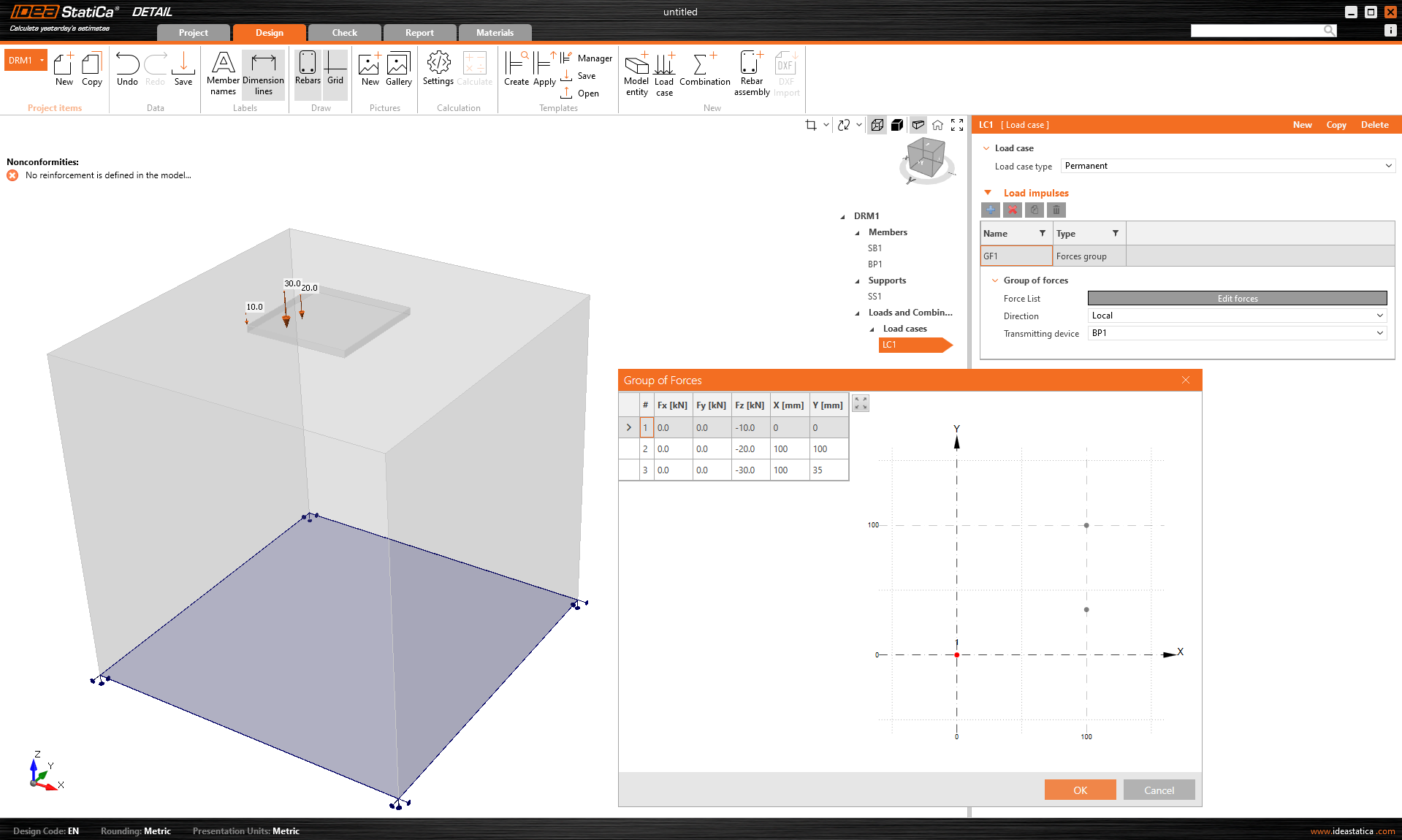
Le groupe des efforts est une entité de charge qui vous permet de spécifier des efforts dans trois directions n'importe où sur le modèle à l'aide d'un tableau. Il peut être référencé au pied de poteau ou à la surface d'un bloc de béton. Pour l'entrée des tableaux, il est à nouveau possible d'utiliser la fonctionnalité copier-coller de la feuille de calcul.
Le poids propre devrait être inclus dans chaque modèle. Par exemple, les fondements en béton chargés d'un moment de flexion ne se renverseront pas aussi facilement.
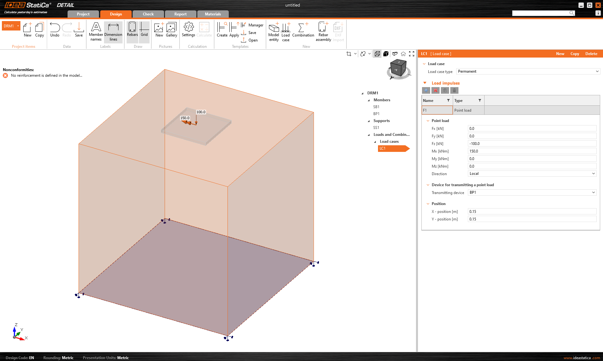
Les charges ponctuelles peuvent être chargées directement sur le pied de poteau avec six efforts internes Fx, Fy, Fz, Mx, My et Mz dans la position générale.
Lors de l'utilisation d'un pied de poteau, l'application de cet effort directement sur un pied de poteau réaliste et déformable peut entraîner une redistribution irréaliste des contraintes sur le pied, les tiges et le béton. Il est donc plus approprié d'utiliser la deuxième option - le tronçon.
Le tronçon
Le tronçon est représenté par une partie courte du poteau au-dessus du pied de poteau qui est modélisé comme une structure d'éléments de coque et se comporte comme une interface physiquement précise entre les efforts internes et le pied. Une base de données de sections standard est utilisée.
L'ensemble des efforts internes à 6 composantes (efforts et moments) est appliqué en un seul point sur la face inférieure du tronçon - c'est-à-dire la base de poteau.
Les contraintes transfèrent les efforts à la face supérieure du tronçon, d'où elles sont naturellement redistribuées à travers le tronçon dans le pied de poteau, les tiges et le béton.
Cette approche préserve l'interaction réaliste de la rigidité entre le poteau et le pied et élimine la nécessité d'une redistribution manuelle ou d'hypothèses artificielles.
Le tronçon a été publié dans la version 25.1 d'IDEA StatiCa.
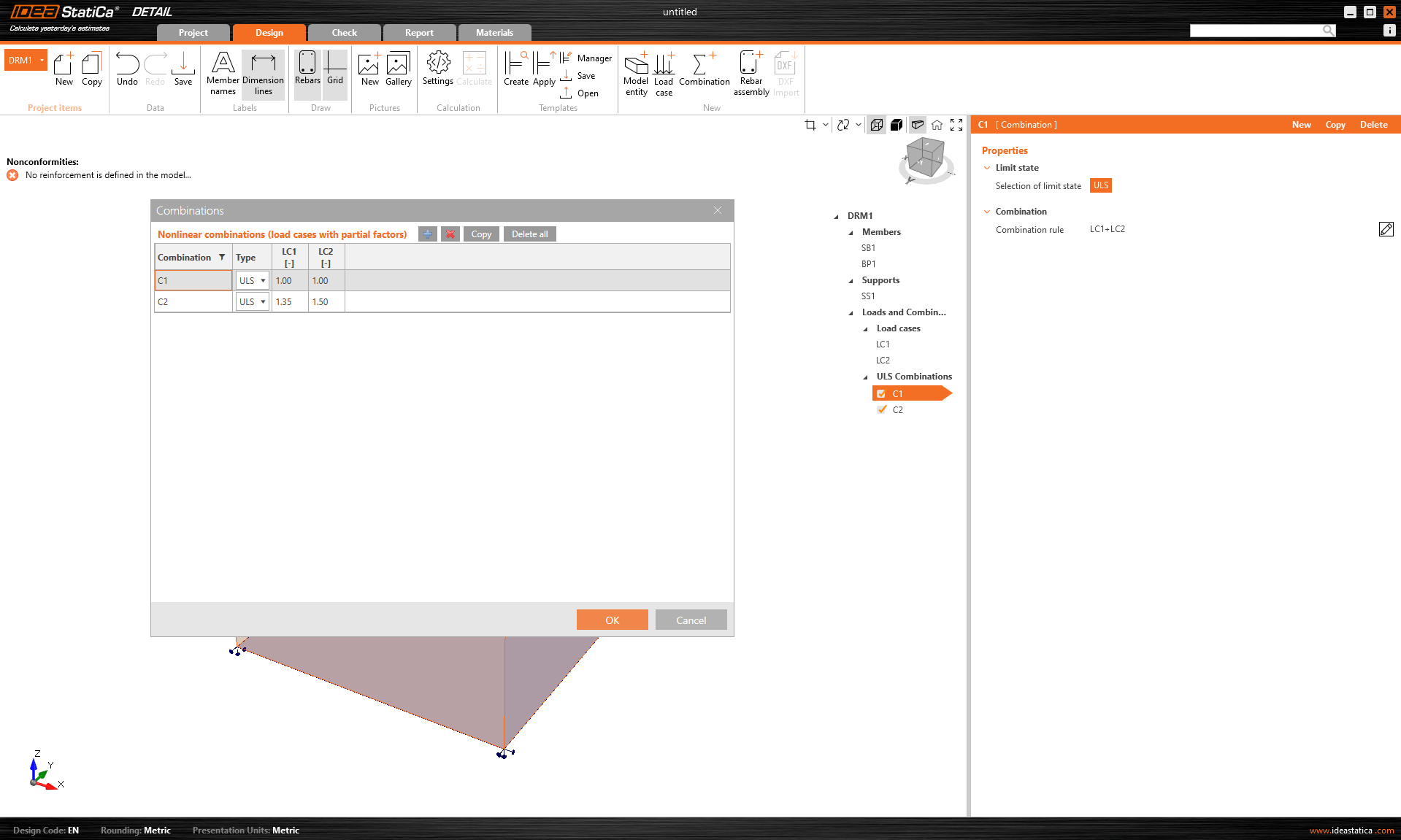
Combinaisons
Puisque l'analyse dans IDEA StatiCa Detail est non linéaire, des combinaisons soi-disant non linéaires sont utilisées. Cela signifie que les cas de charge individuels ne sont pas calculés et que les résultats ne sont pas additionnés. Au contraire, les cas de charge du même type de charge sont additionnés avant le calcul, bien sûr avec les coefficients respectifs définis dans les combinaisons, et les combinaisons individuelles sont ensuite calculées. C'est pourquoi l'existence d'au moins une combinaison est une condition préalable au lancement du calcul.
Seules les combinaisons pour l'ELU peuvent être définies.
Le modèle peut être renforcé avec un Groupe de barres 3D. Ce type de ferraillage contient de nombreuses options, que nous allons parcourir dans le texte suivant. Ainsi, 4 types de Définitions de forme de barre peuvent être spécifiés :
- Par deux points
- Sur l'arête de surface
- Sur l'arête de surface sur plusieurs arêtes
- Sur polyligne
Pour chacun de ces éléments, vous pouvez bien entendu spécifier le diamètre et le matériau, y compris le type d'ancrage au début et à la fin des barres.
La définition de forme de barre Par deux points est explicite. Vous devez saisir deux ensembles de coordonnées cartésiennes X, Y, Z.
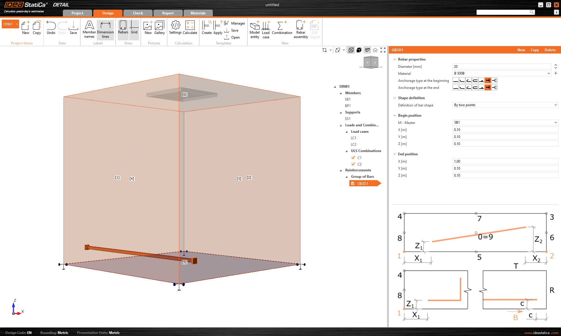
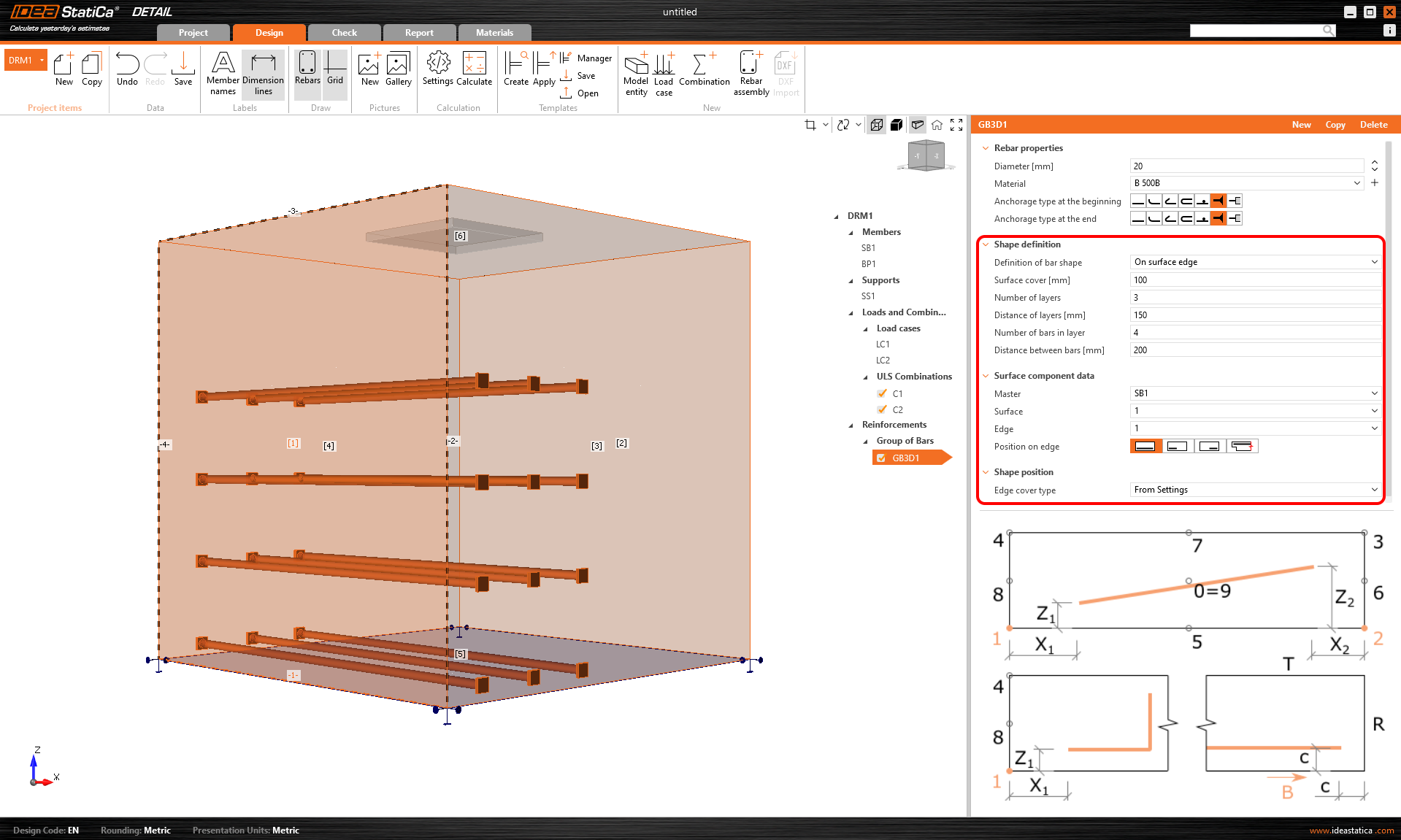
La définition Sur l'arête de surface offre de nombreux contrôles pour positionner les armatures à l'emplacement requis. Vous pouvez saisir des barres d'armature sur plusieurs couches avec plusieurs barres dans une couche, avec des distances spécifiées entre les barres dans et entre les couches. Bien entendu, il est également nécessaire de spécifier la surface de référence et l'arête. Ensuite, vous devez spécifier l'Enrobage de surface, qui définit la distance par rapport à la surface de référence (depuis la surface [1] dans la figure ci-dessous), et l'Enrobage d'arête, qui définit la distance des inserts par rapport aux surfaces latérales (depuis les surfaces [4], [5] et [2] dans la figure ci-dessous), peut être spécifié comme Depuis les paramètres ou Saisie utilisateur. La valeur d'enrobage par défaut (Depuis les paramètres) pour l'élément de projet actif se trouve dans le premier élément de l'arborescence (appelé par défaut DRM1). Cela a été défini au début de cet article. L'enrobage d'arête peut être défini comme une valeur unique pour chaque Groupe de barres.
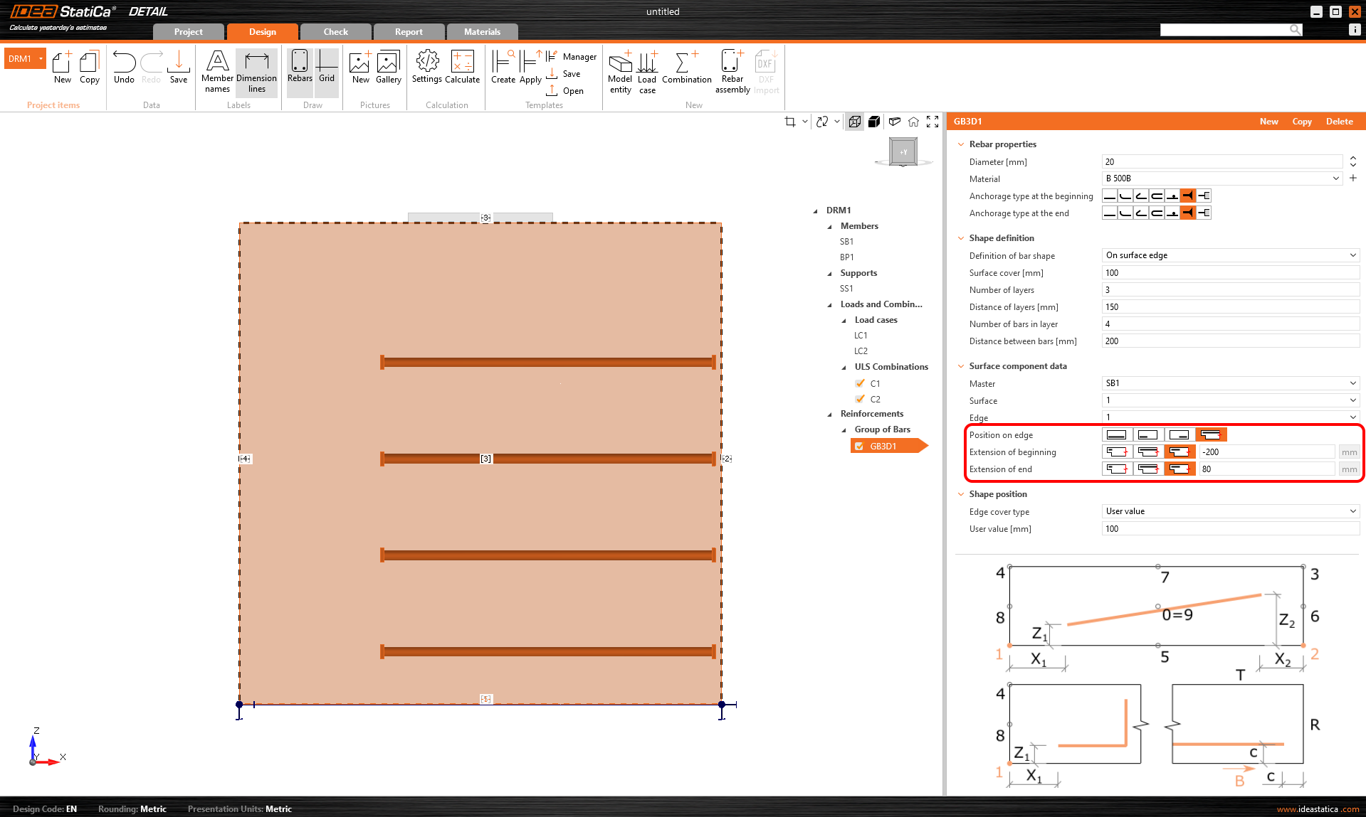
Enfin, la Position sur l'arête peut être modifiée pour ce type de saisie. Par exemple, comme illustré dans la figure ci-dessous, il est possible de spécifier le ferraillage de sorte que l'Enrobage d'arête défini par l'utilisateur soit appliqué uniquement à la surface inférieure [5]. Les surfaces latérales sont contrôlées par l'Extension du début et de la fin.
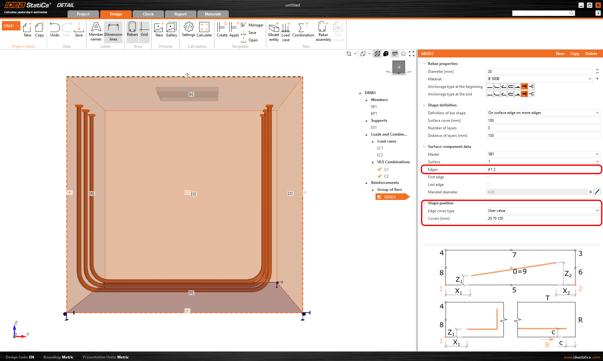
Un autre type de définition est Sur l'arête de surface sur plusieurs arêtes. Il est ici possible de spécifier une liste d'arêtes ou de surfaces sur lesquelles le ferraillage sera placé, ainsi qu'une liste de couches d'enrobage pour chaque surface, comme illustré dans la figure suivante.
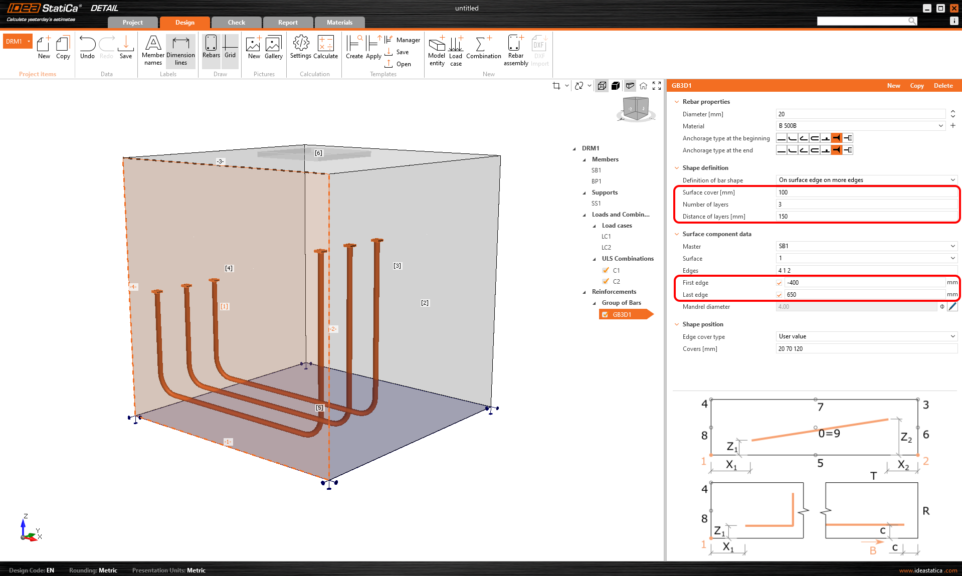
L'enrobage peut également être spécifié à l'aide de l'option Depuis les paramètres, comme pour le précédent. Là encore, il est possible de décaler le ferraillage par rapport à la surface de référence à l'aide de l'Enrobage de surface et de spécifier le Nombre et la Distance des couches. Il est également possible d'allonger ou de raccourcir les extrémités depuis la Première arête et la Dernière arête.
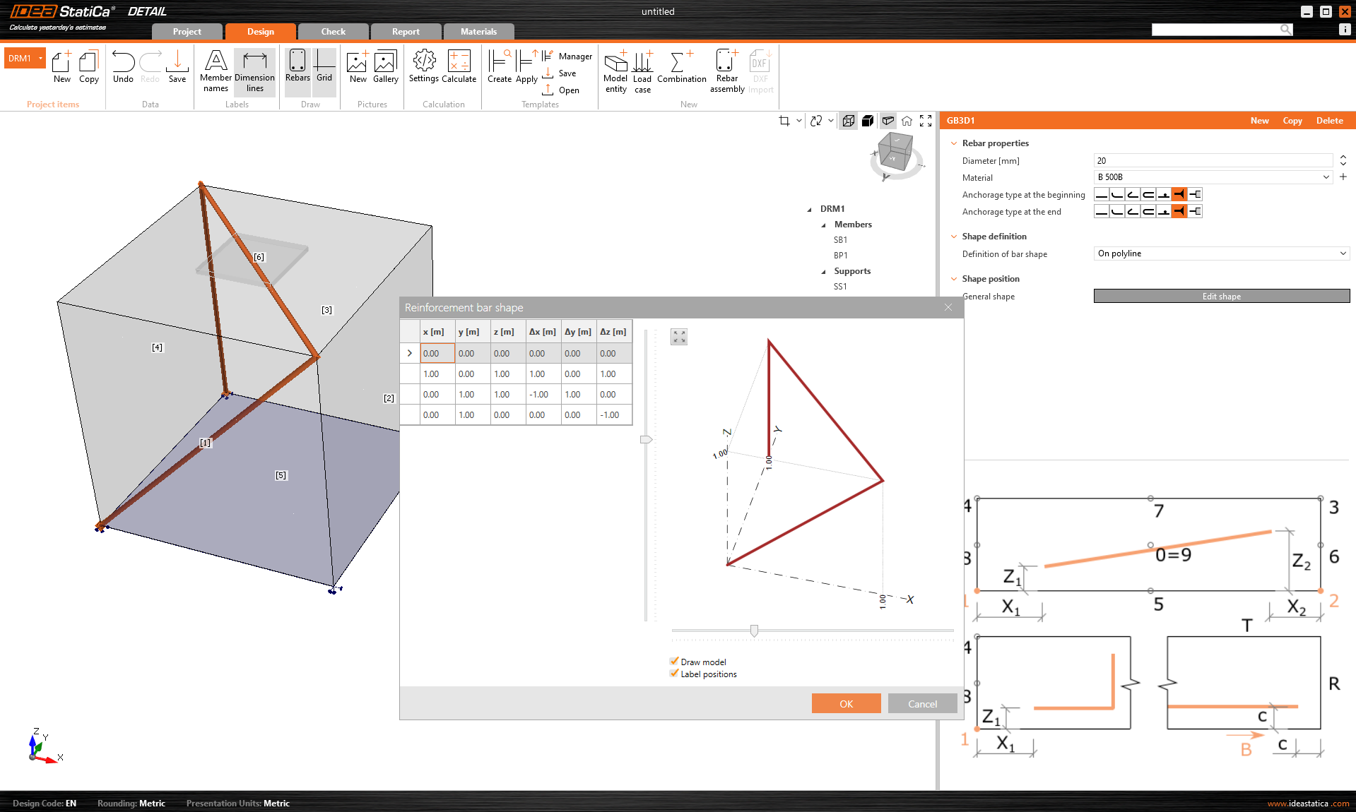
La dernière façon de définir le ferraillage est Sur polyligne. Comme pour les entités de modèle mentionnées ci-dessus, le ferraillage peut être spécifié à l'aide d'une liste de coordonnées copiées depuis un tableur. Dans ce cas, une scène 3D avec le ferraillage affiché est en outre disponible pour une meilleure orientation, permettant des rotations autour de deux axes.
L'ancrage dans un bloc de béton simple peut être modélisé et vérifié dans IDEA StatiCa Connection. Parfois, il peut être utile ou nécessaire d'ajouter du ferraillage au bloc de béton. Bien que cette capacité ne soit pas disponible dans l'application Connection, nous avons 3D Detail. 3D Detail se concentre sur la résolution des ancrages dans les blocs de béton et sur l'analyse des éléments d'ancrage et du bloc de béton lui-même. De plus, un lien direct est mis en place entre les applications Connection et Detail pour simplifier le processus.
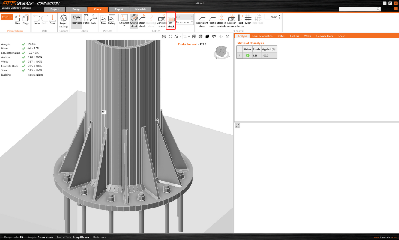
Les utilisateurs de Connection qui conçoivent des ancrages selon l'Eurocode peuvent importer leur modèle de Connection vers l'application avancée 3D Detail en cliquant sur un seul bouton.
Comment ça fonctionne ?
- L'importation n'est autorisée que pour les ancrages. S'il n'y a pas de bloc de béton dans le modèle Connection, l'exportation vers Detail est désactivée (« Vérification de béton armé »).
- Il faut calculer le modèle dans Connection. Si les résultats ne sont pas disponibles, l'icône d'exportation (« Vérification de béton armé ») est désactivée.
- Un seul bloc de béton est autorisé pour l'importation/exportation.
Pour une liste complète des limitations et des explications complémentaires, voir l'article Limites connues de 3D Detail.
L'attache est importée, y compris
- Bloc de béton
- Tiges
- Pied de poteau
- Charges
Informations et paramètres supplémentaires définis en fonction des paramètres correspondants dans Connection :
- Transfert de cisaillement (par tiges, bêches et frottement)
- Matériau
- Type d'ancrage : par adhérence / encastré
- Type d'ancrage à l'extrémité : Rondelle/Droit/Crochet
- Coefficient de frottement
Comment exporter l'ancrage de Connection vers Detail
Tout d'abord, créez un modèle d'ancrage dans Connection selon l'Eurocode et cliquez sur le bouton Calculer.
Lorsque les résultats existent, l'exportation des semelles est activée. En cliquant sur le bouton « Vérification de béton armé » au ruban, une boîte de dialogue demandant l'emplacement et le nom du fichier Detail nouvellement créé apparaît.
Après une exportation réussie, le projet dans Detail est créé. La géométrie du bloc de béton et du pied de poteau, la position et les attributs des tiges et la charge sont automatiquement transférées vers Detail. L'appui superficiel situé sur la surface inférieure du bloc de béton est automatiquement créé.
La partie la plus délicate de ce processus est l'importation de la charge. Pour chaque effet de charge calculé dans Connection, le cas de charge et la combinaison ELU correspondants sont automatiquement créés dans Detail.
- Le pied de poteau est chargé par des efforts dans les soudures qui sont modélisés comme un groupe d'efforts. Pour le chargement du pied de poteau lui-même, le chargement importé est représenté par un groupe d'efforts selon les contraintes dans les soudures entre le pied de poteau et les éléments en acier dans le modèle Connection.
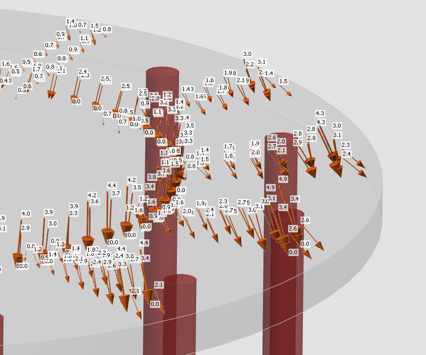
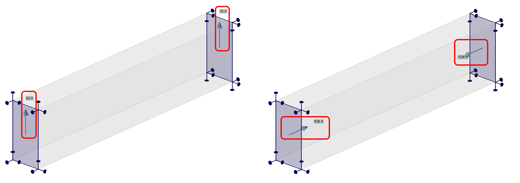
- Les tiges sont modélisées et chargées indépendamment du pied de poteau et elles sont chargées axialement par des charges ponctuelles. Le chargement des tiges est représenté dans la scène par deux flèches dans les directions opposées. Une flèche représente l'effort de traction agissant uniquement sur la partie supérieure de la tige. L'autre représente l'effort de compression agissant sur le pied de poteau.
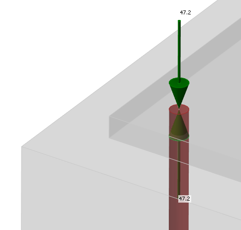
La case à cocher « Transfert des efforts axiaux » est décochée par défaut parce que les tiges sont chargées par les efforts directement.
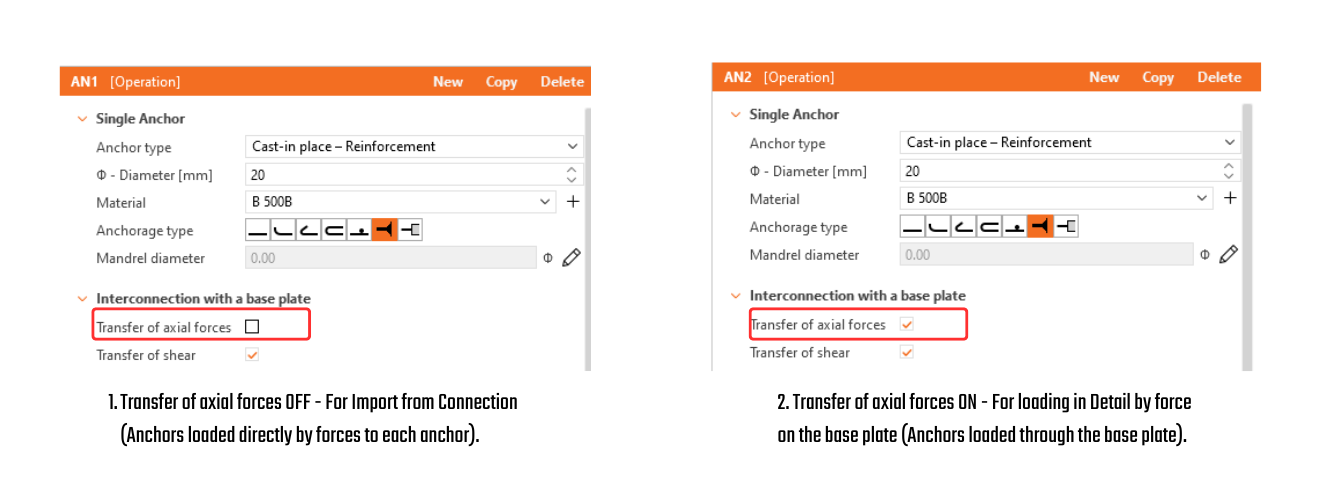
- Le cisaillement est transféré selon le paramétrage dans Connection par l'une des options suivantes – tiges, bêches ou frottement. Si l'effort de cisaillement est transféré par des tiges, vous pouvez désactiver des tiges spécifiques en décochant la case « Transfert de cisaillement ». Si le frottement ou les bêches sont sélectionnées, le cisaillement dans les tiges n'est jamais pris en compte dans le modèle.
Il ne reste qu'à ajouter le ferraillage et calculer le modèle.
Vous trouverez plus d'informations générales sur Detail comme solution pour votre ancrage dans l'article 3D Detail hors de Bêta.
Note : Les vérifications de norme dans 3D Detail ne sont disponibles actuellement que pour l'Eurocode (EN).
Publié dans IDEA StatiCa version 24.1.
L'affichage des résultats est très similaire à celui du Detail 2D. Cependant, il existe quelques différences majeures, notamment en ce qui concerne les résultats sur le béton et les résultats des ancrages. Dans la section suivante, nous passerons en revue tous les résultats disponibles, en nous concentrant sur les différences mentionnées. Dans l'onglet de vérification, vous pouvez consulter 4 types de résultats :
- Récapitulatif
- Vérification de la résistance et des ancrages selon les codes
- Ancrage du ferraillage
- Autres résultats supplémentaires
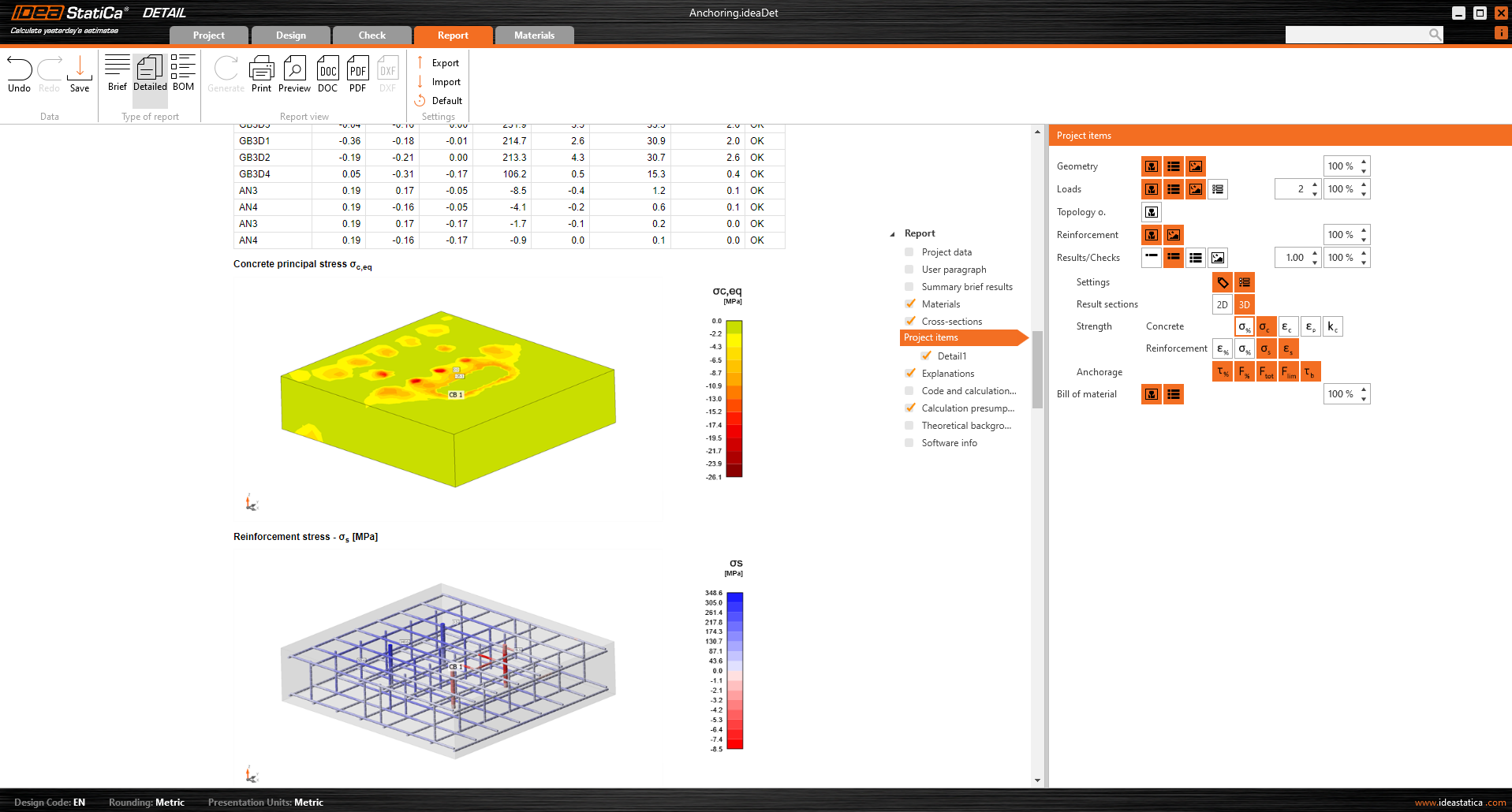
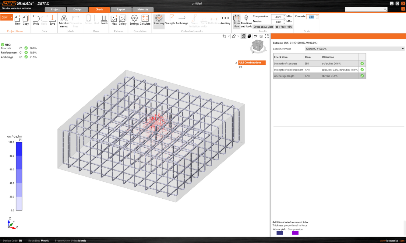
Le flux de contraintes dans les résultats du Récapitulatif vous montre les vecteurs des contraintes principales de compression dans le béton et le taux de travail du ferraillage et des ancrages pour vous donner un aperçu général.
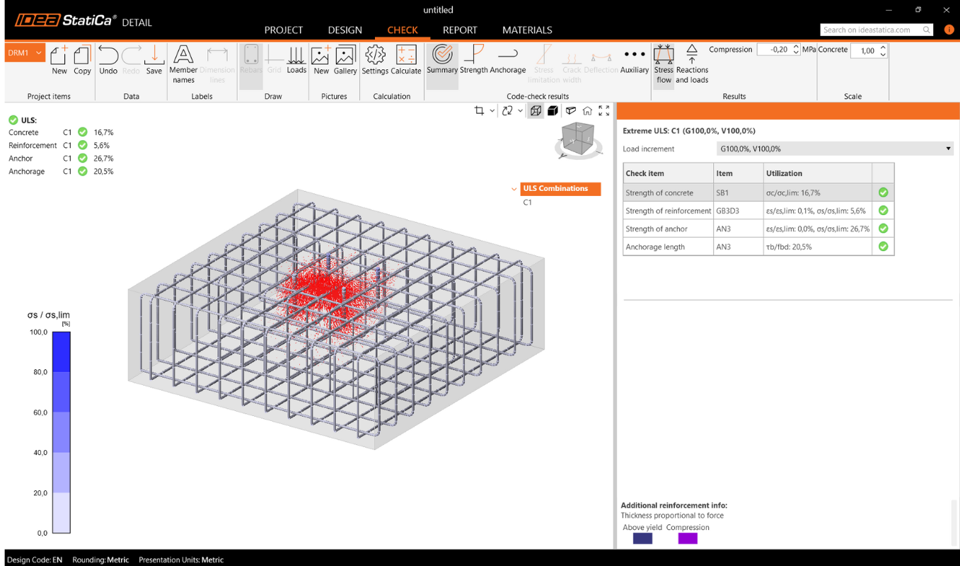
Vérification de la résistance du béton, du ferraillage et des ancrages
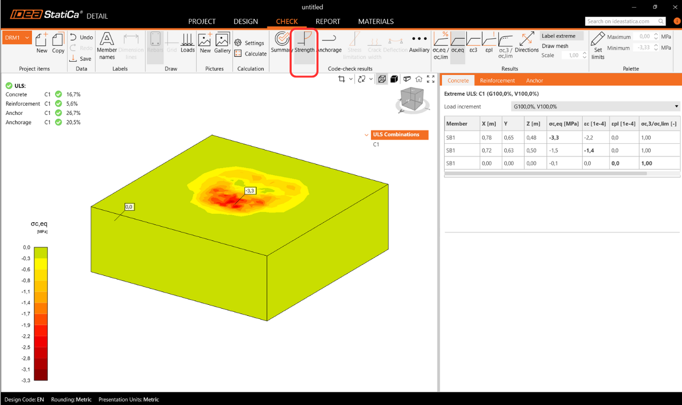
Dans la vérification de la Résistance, vous pouvez afficher la redistribution des contraintes et des déformations pour le béton. Dans le ruban supérieur de la barre d'outils Résultats, vous pouvez contrôler ce qui sera affiché. Il est également possible d'afficher les rapports σc,eq/σlim, et ε/εlim ainsi que la déformation plastique, le niveau de triaxialité σc3/σlim, et la direction de la contrainte principale pour le béton. Tous les résultats de la Résistance sont liés à l'État Limite Ultime.
Remarque : Vous pouvez remarquer que la contrainte principale équivalente σc,eq est nulle juste en dessous de la platine de base comprimée. Veuillez lire le Contexte théorique où σc,eq est définie. Ou vous pouvez consulter cet article de vérification, où ce phénomène est expliqué et vérifié à l'aide d'un essai triaxial bien connu : Contrainte triaxiale – l'effet de confinement actif
Les matériaux peuvent être modifiés dans les propriétés.
La vérification du ferraillage est effectuée de manière très similaire, où nous comparons à nouveau les valeurs limites avec la contrainte/déformation calculée - σs/σlim, et εs/εlim.
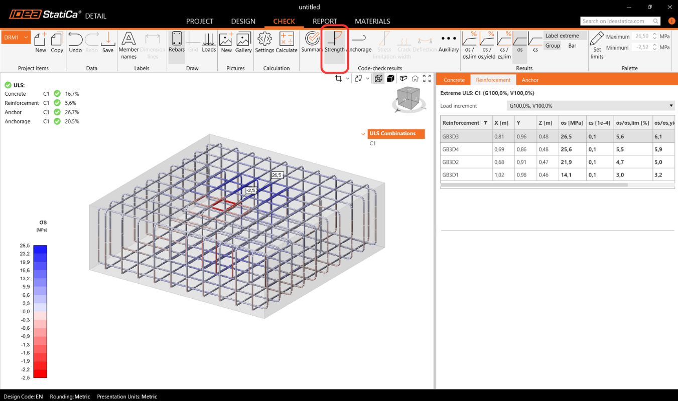
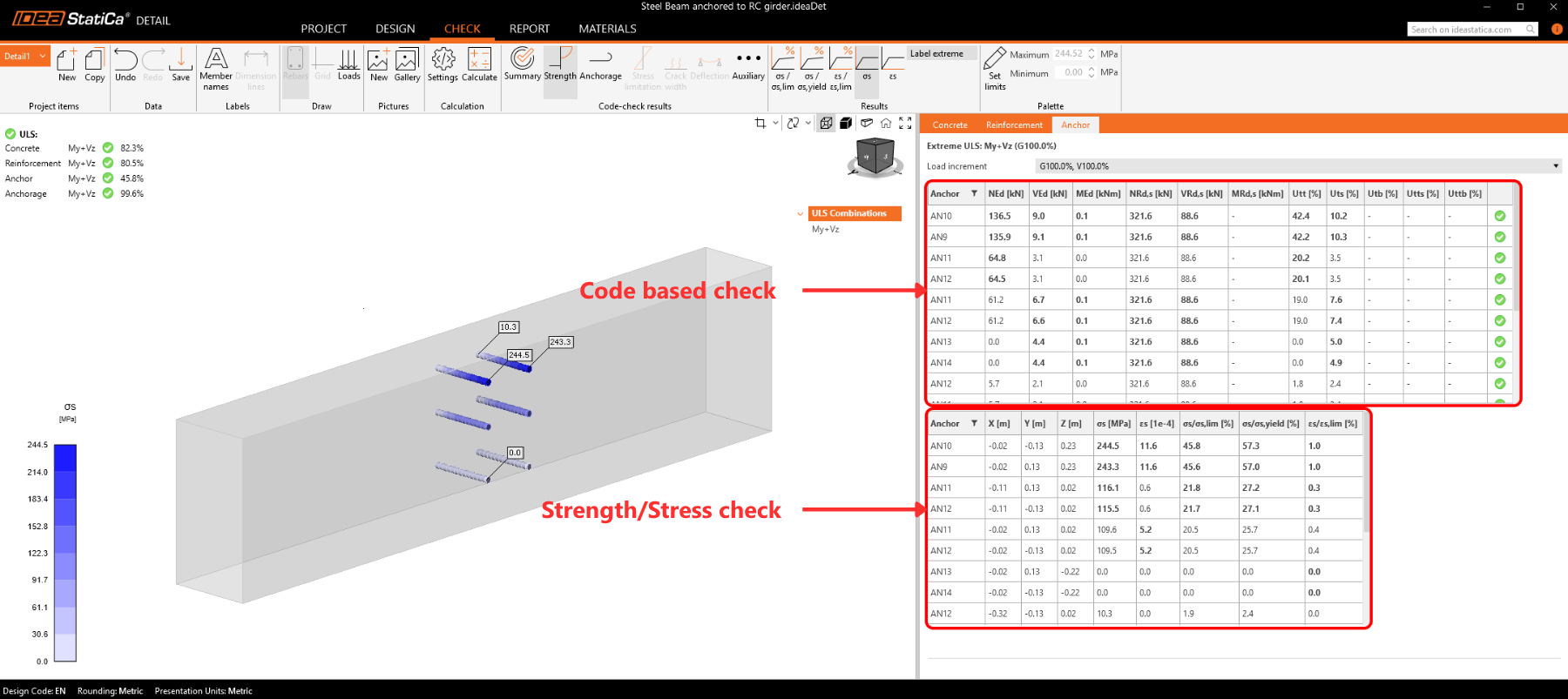
Pour les ancrages, nous disposons de deux vérifications. L'une est identique à celle du ferraillage — comparaison des valeurs limites - σs/σlim, et εs/εlim.
Remarque : Vous pouvez remarquer que chaque ancrage est vérifié en plusieurs positions, qui sont automatiquement calculées comme des cas extrêmes.
Vérification normative des ancrages selon le code de calcul
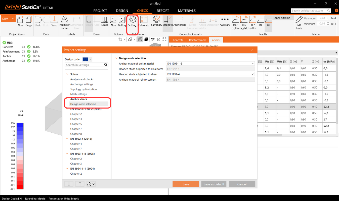
De plus, nous disposons de vérifications basées sur les codes de calcul (EN, ACI/AISC, AUS), qui sont effectuées de manière empirique conformément à la norme. La norme spécifique considérée peut être consultée dans les paramètres, où il est également possible d'en sélectionner une autre en fonction du type d'ancrage utilisé (platine de base en contact direct avec le béton, platine de base scellée au mortier, et platine de base avec jeu), ainsi que la norme requise selon les pratiques régionales.
Codes implémentés : EN 1992-4, EN 1993-1-8, EN 1994-1-1, ACI318-19, AISC 360-16, AS3600, AS 5216, AS 4100
Les paramètres de la norme peuvent être modifiés dans les Paramètres du projet, où les chapitres apparaîtront selon la norme sélectionnée lors de la création du projet. Lors de l'importation depuis Connection, il est recommandé de vérifier que la même norme est définie.
Dans le chapitre Contexte théorique - Vérifications à l'État Limite Ultime, chaque vérification est expliquée en détail, y compris toutes les formules utilisées.
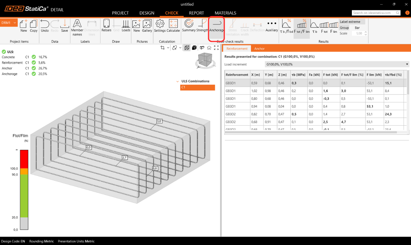
Ancrage du ferraillage
La vérification de l'Ancrage vous fournit des informations sur la contrainte d'adhérence et l'effort total sur le ferraillage et les ancrages.
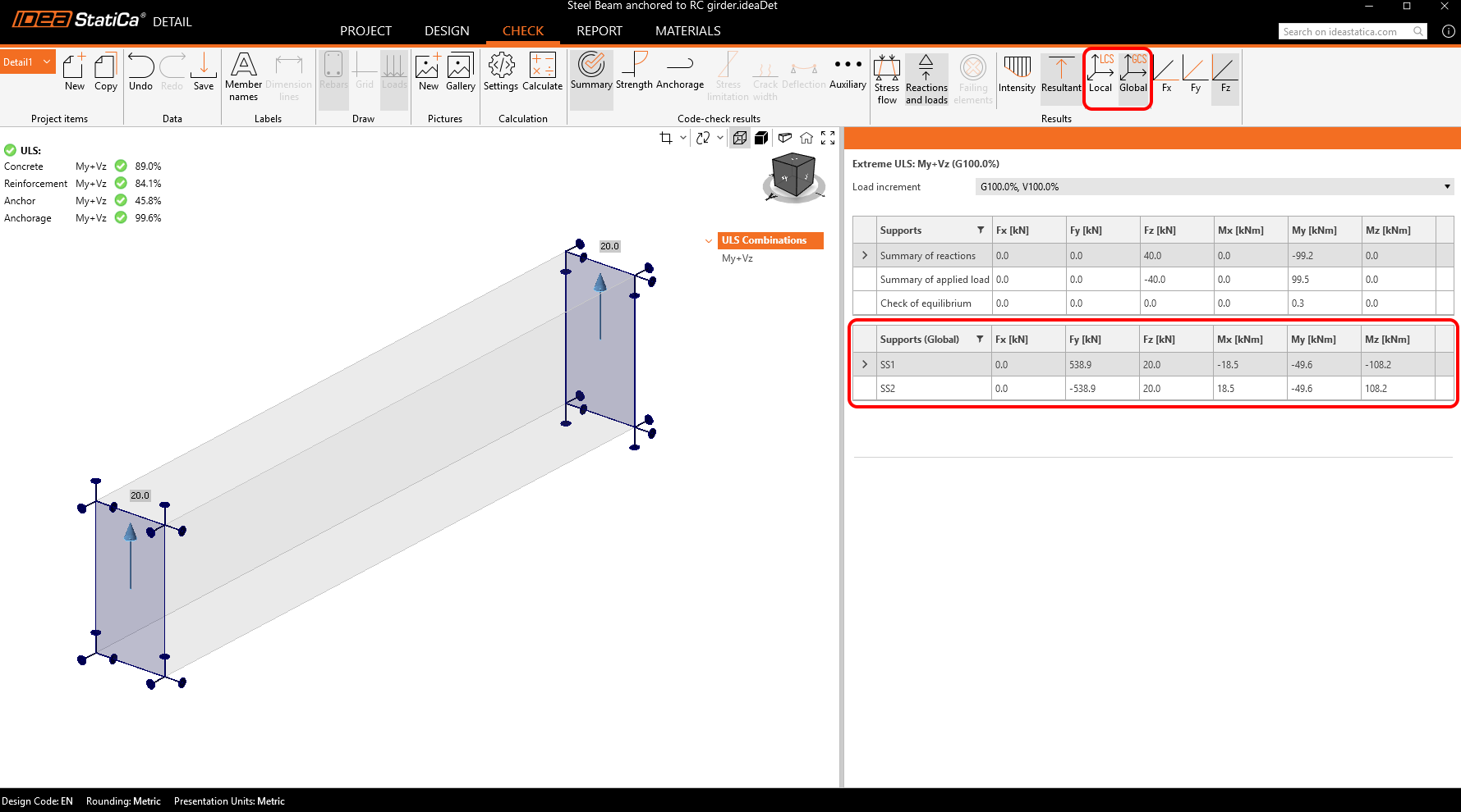
Réactions d'appui surfaciques
La section Réactions et Charges inclut une option pour afficher les réactions d'appui surfaciques. Les réactions peuvent être visualisées selon deux modes :
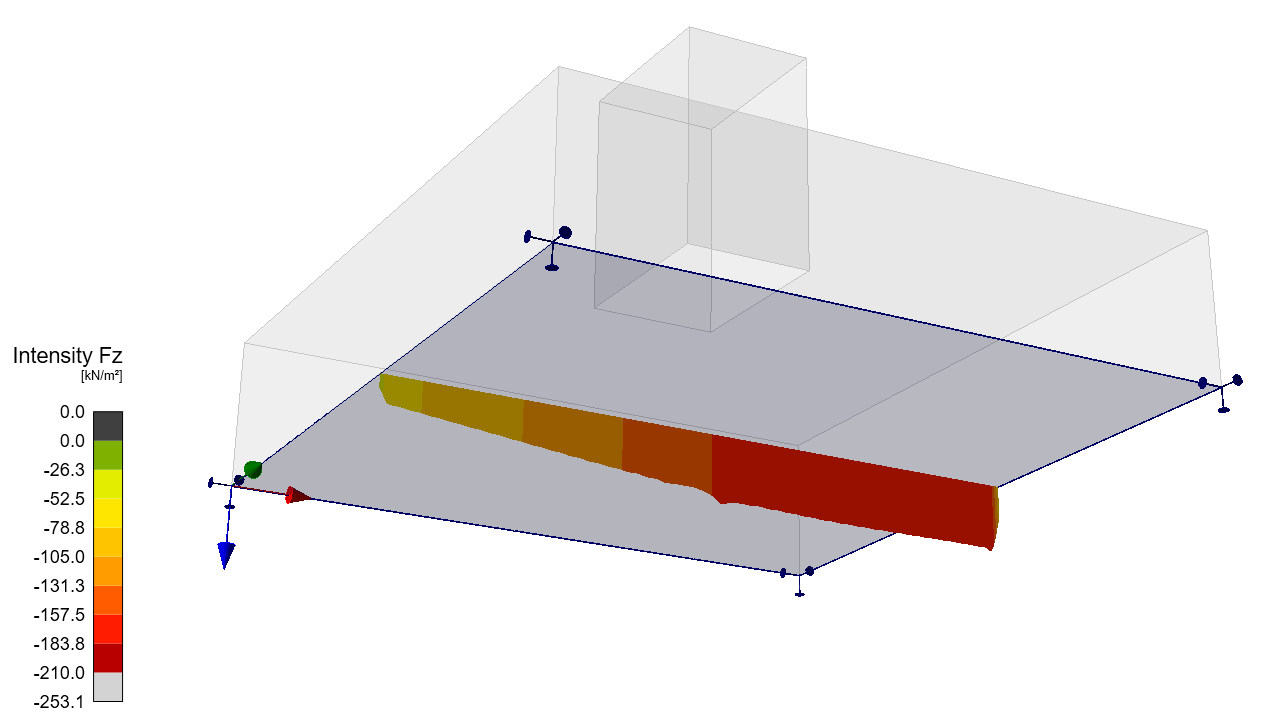
- Intensité – Les réactions surfaciques sont affichées sur la face appuyée du bloc de béton à l'aide d'isobandes pour illustrer la distribution sur la zone d'appui.
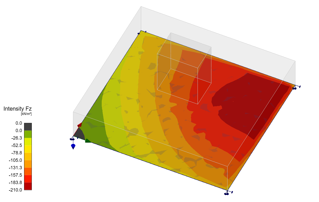
- Résultante – La réaction résultante pour chaque appui est affichée sous forme de flèche au centre de gravité de l'appui, indiquant la magnitude et la direction.
Pour les deux modes, les réactions peuvent être affichées soit dans le Système de Coordonnées Global (SCG) soit dans le Système de Coordonnées Local (SCL) de l'appui.
Un nouveau tableau dans la Grille de Propriétés liste les réactions récapitulatives pour les appuis individuels, également disponibles en coordonnées globales ou locales.
De plus, la distribution des réactions peut être visualisée dans les vues en coupe créées par l'utilisateur.
Résultats avancés supplémentaires
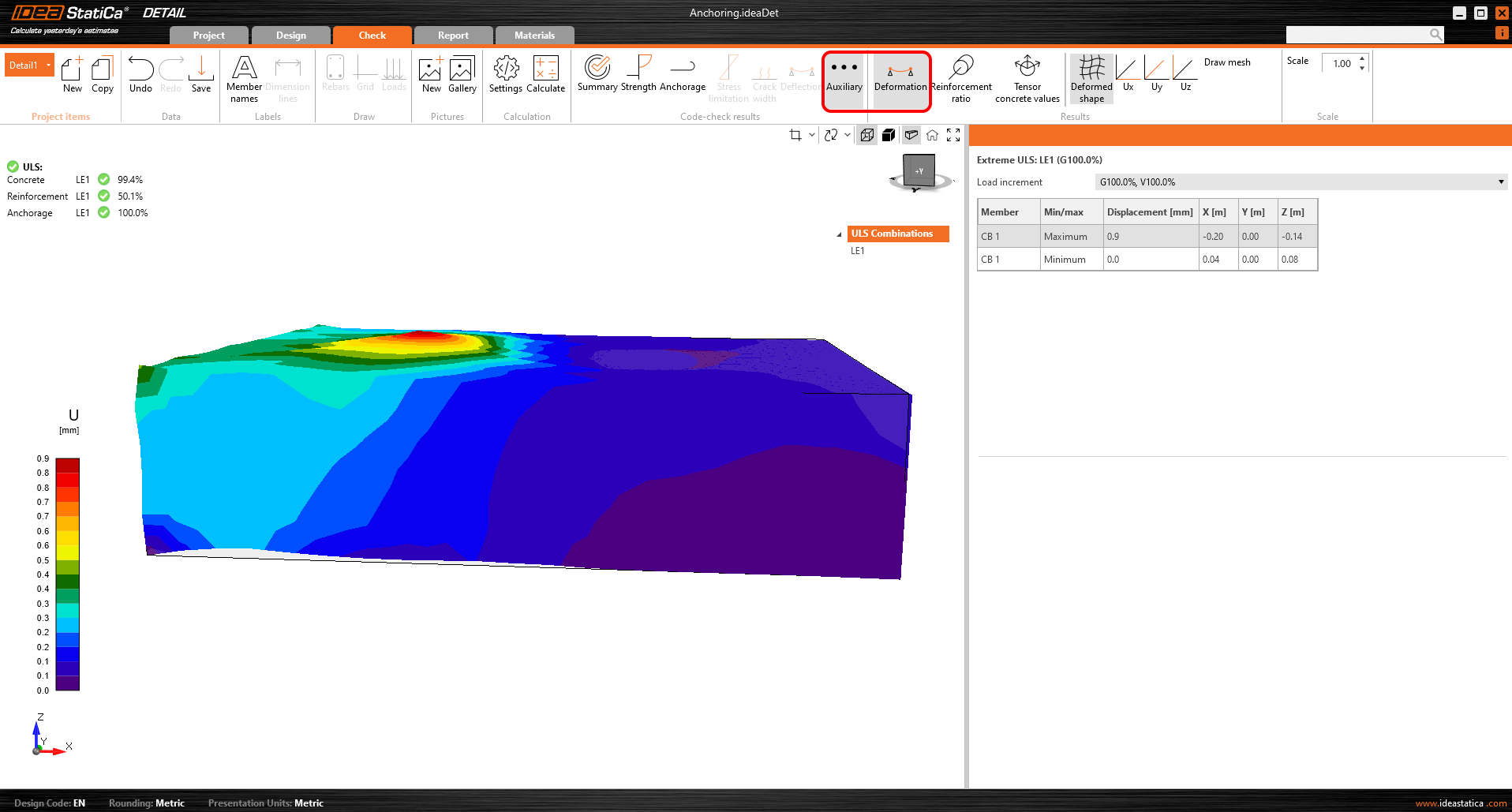
Enfin, vous pouvez consulter les résultats Auxiliaires dans l'application - Déformation, Taux de ferraillage et Valeurs tensorielles du béton. Le premier type, Déformation, peut afficher les déformations à l'échelle du modèle non linéaire à l'ELU.
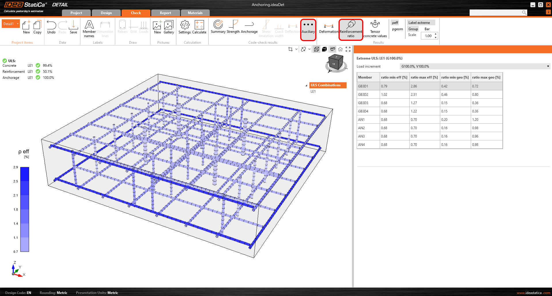
Le taux de ferraillage affiche les valeurs utilisées pour calculer l'effet de raidissement en traction.
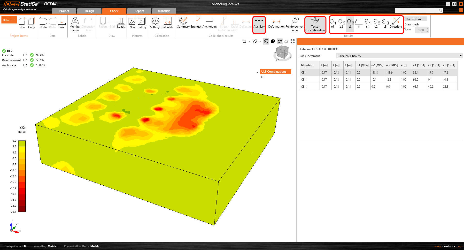
Les valeurs tensorielles du béton vous permettent d'afficher les intensités des contraintes principales dans le béton et leur direction.
Les sections de résultats peuvent également être utilisées.
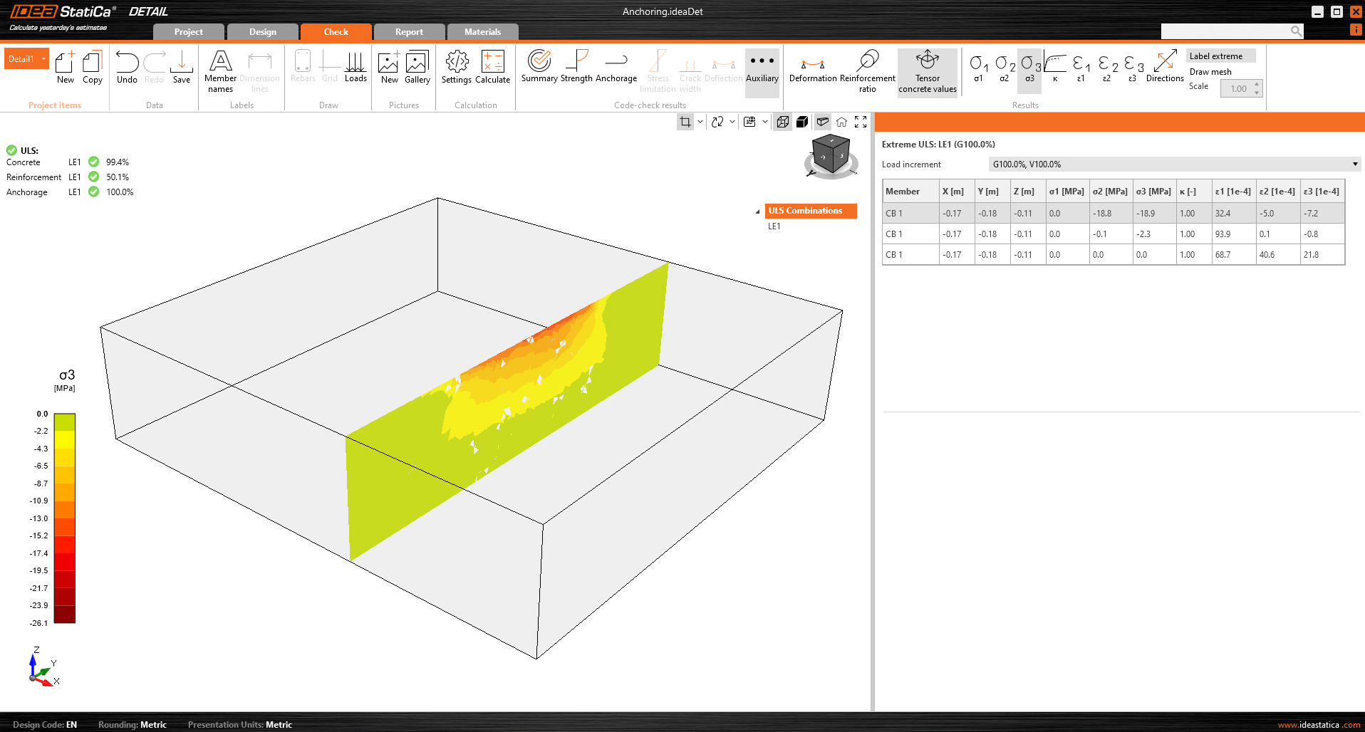
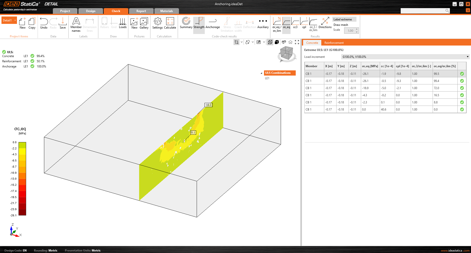
Les résultats de section permettent d'obtenir un aperçu des contraintes au sein de l'élément en béton. Il est possible de créer un nombre quelconque de sections dans n'importe quel plan.
Pour les modèles 3D, il existe une option d'affichage des résultats pour le béton - Résultats de section. Pour définir ou modifier les sections, vous devez utiliser le bouton de section dans le contrôle de vue, situé dans le coin supérieur droit de la scène.
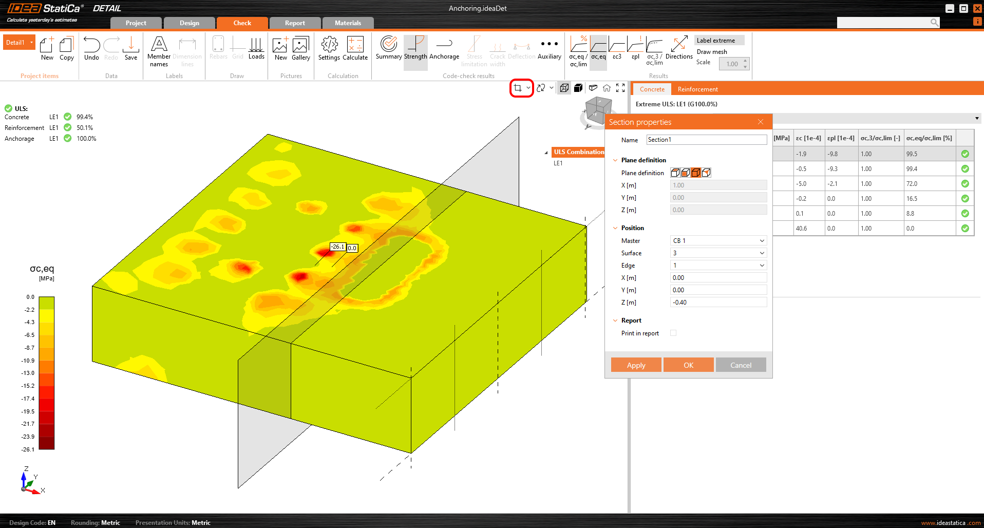
Vous pouvez ensuite simplement activer le bouton de section et les résultats seront affichés via une section spécifiée.
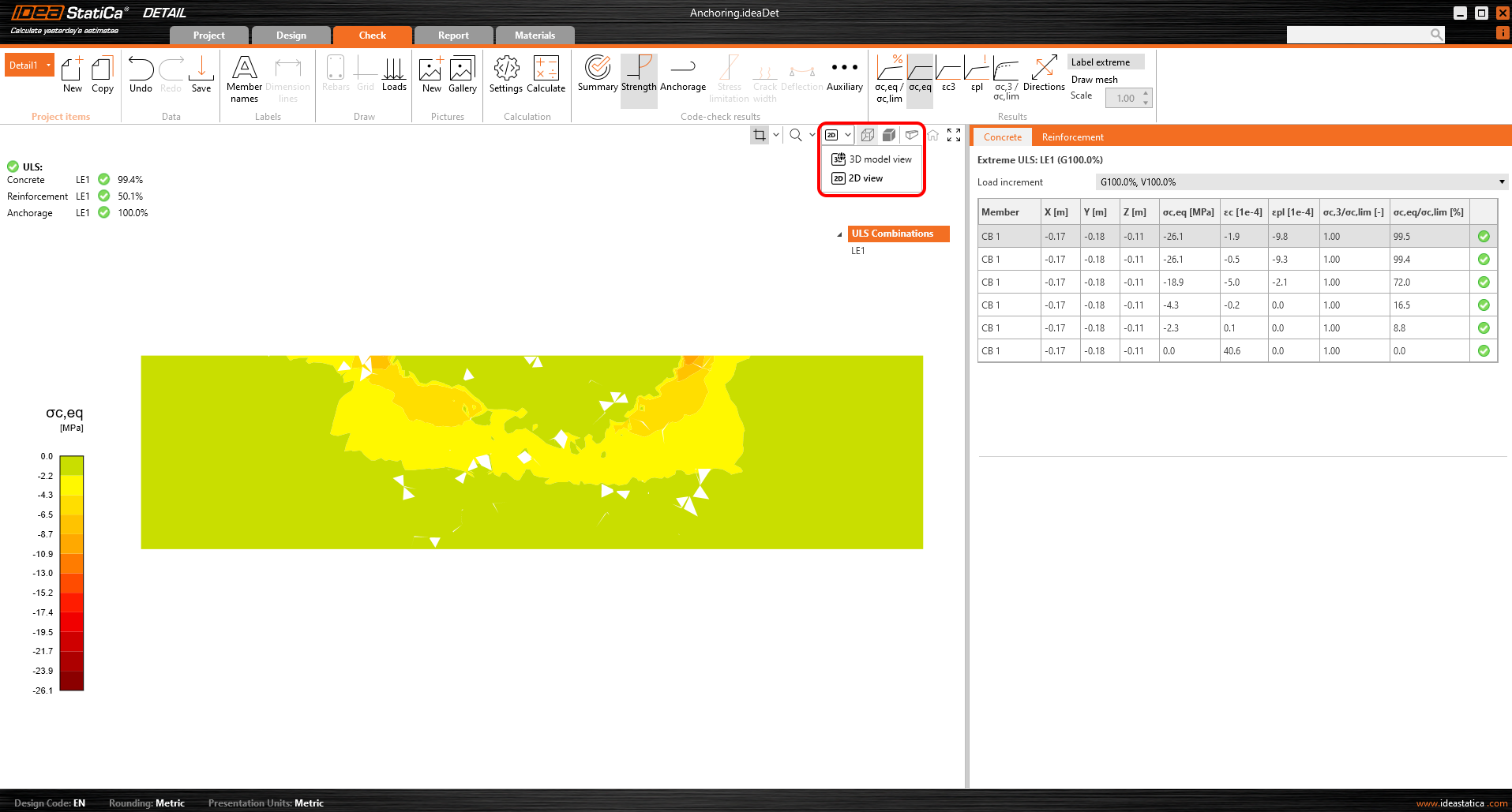
Il est également possible de passer de la vue 3D à la vue 2D et d'afficher la section sélectionnée en 2D pour plus de clarté.
Vérification des contraintes
Pour une meilleure compréhension des résultats et de la théorie implémentée dans le Detail 3D, l'iconographie a été considérablement améliorée. Dans la section « Résistance », sous l'évaluation des contraintes du béton, vous trouverez de nouvelles icônes et, surtout, des info-bulles expliquant la théorie de base. Ces info-bulles correspondent aux bases théoriques.
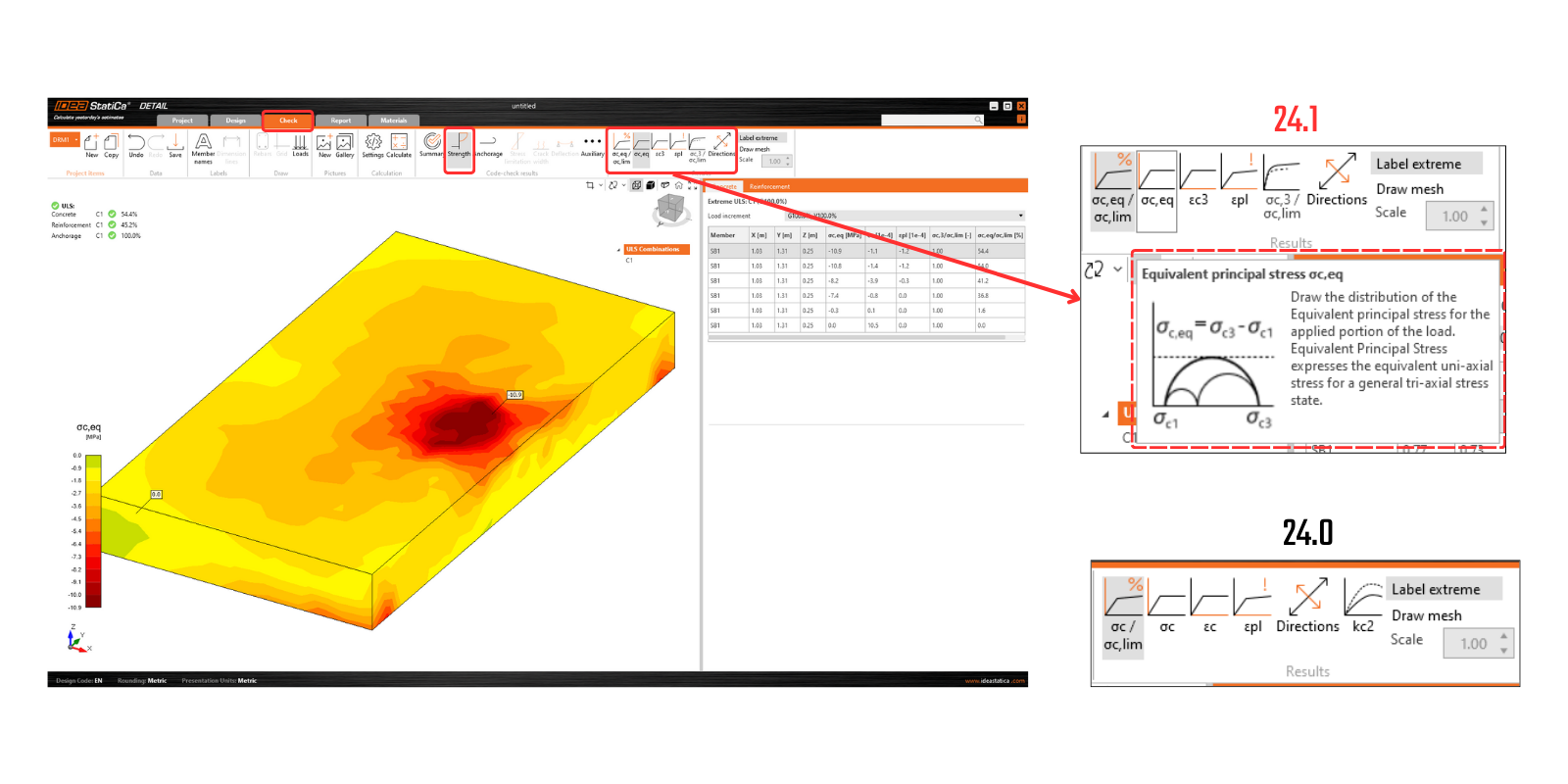
Disponible à partir de la version 24.0.2 d'IDEA StatiCa
Comme il est standard dans nos applications, tous les résultats peuvent être imprimés dans un rapport généré automatiquement, incluant les bases théoriques, les paragraphes utilisateur, et bien plus encore.