
Limitations connues pour Detail 3D
Introduction
En préambule, définissons l'objet de l'application. Dans la version actuelle, nous avons développé des outils et vérifié la solution uniquement pour l'ancrage de structures acier dans des blocs en béton armé simples.
Le texte suivant est divisé en deux parties : les limitations de l'application et de la méthode elle-même, et les limitations de l'import depuis IDEA StatiCa Connection.
Limitations de l'application
Béton armé
Le CSFM 3D n'est pas conçu pour le béton non armé ou le béton faiblement armé. Dans ce cas, le résultat du calcul peut conduire à des résultats trompeurs ou à une divergence du calcul non linéaire.
Vous pouvez en savoir plus dans les bases théoriques.
La principale raison pour laquelle seuls les éléments en béton armé doivent être modélisés dans l'application est que la résistance à la traction du béton est négligeable. Toutes les contraintes de traction doivent donc être reprises par le ferraillage.
La deuxième raison est la suivante : dans IDEA StatiCa Detail 3D, la mécanique de la rupture n'est pas utilisée. Le modèle ne simule pas la propagation explicite des fissures et n'utilise pas les paramètres de mécanique de la rupture du béton (G_f, K_IC, forme de la surface de rupture). Le béton est modélisé comme un matériau ductile avec une branche plastique horizontale en compression — une fois que la contrainte limite de compression est atteinte, la contrainte reste constante et seules les déformations continuent d'augmenter jusqu'à une limite prescrite. En conséquence, Detail 3D peut capturer la redistribution plastique des contraintes et des déformations dans les régions D, mais ne modélise pas explicitement les mécanismes de rupture fragile régis par la mécanique de la rupture (par exemple, rupture par cisaillement pur du béton non armé, propagation instable d'une fissure dominante unique, etc.).
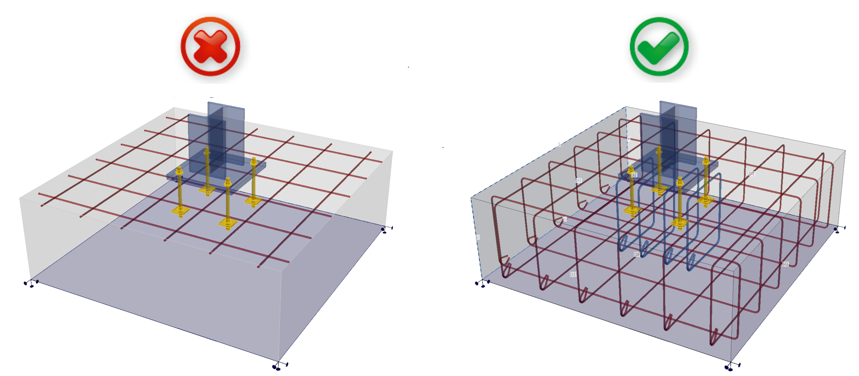
En résumé, vos modèles doivent être conformes à la définition du béton armé telle que présentée dans les normes internationales. Respectez les règles de ferraillage et obtenez des résultats corrects.
État Limite Ultime
Tous les calculs et vérifications normatives sont implémentés pour l'ELU uniquement. La définition des matériaux et la méthode de calcul elle-même doivent être différentes pour l'ELS. Vous pouvez observer cette différence dans Detail 2D.
Adoucissement en compression
Définissons d'abord ce qu'est l'adoucissement en compression : Le béton en compression perd sa résistance et sa rigidité lorsqu'il est simultanément fortement fissuré en traction, c'est-à-dire lorsque de grandes déformations principales de traction transversales sont présentes.
Dans les cas où la résistance est gouvernée par une bielle comprimée (diagonale comprimée) traversant un béton fortement fissuré, Detail 3D tend à surestimer la capacité (c'est-à-dire à être légèrement non conservateur) si le résultat est interprété directement comme la capacité ultime réelle.
Pour ces raisons, le module 3D est adapté uniquement à la vérification de la résistance des ancrages dans des blocs en béton armé simples.
Bien qu'il soit possible de modéliser, par exemple, un chevêtre de pieux à l'aide d'appuis sur une petite surface, la vérification n'est pas fiable car l'effet d'adoucissement devient significatif, notamment dans les problèmes liés au poinçonnement. La même situation peut se produire dans le cas d'une dalle mince avec un poteau posé dessus, et dans d'autres cas similaires.
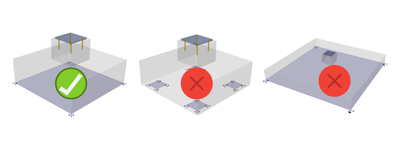
Pour ces situations, il est nécessaire d'implémenter l'adoucissement du béton, qui n'est actuellement disponible que dans le module 2D. Par conséquent, le module 3D ne peut être utilisé que pour la vérification des ruptures où cet effet n'a aucune influence.
Vérification des ancrages
L'élément d'ancrage est défini comme étant capable de transférer des efforts normaux de traction ou de compression ainsi que des efforts de cisaillement, en tenant également compte de la rigidité en flexion, comme décrit dans les bases théoriques.
Nous prenons en charge les vérifications normatives conformément aux normes applicables (EN uniquement), ainsi IDEA StatiCa Detail peut être utilisé de manière indépendante pour l'évaluation des ancrages (ancrages, ferraillage, béton).
Normes implémentées : EN 1992-4, EN 1993-1-8, EN 1994-1-1
Pour la vérification des autres composants de l'assemblage (soudures, platines, etc.), vous devez utiliser IDEA StatiCa Connection, où vous pouvez également effectuer la vérification complète des ancrages pour le béton non armé. L'ancrage dans Connection — avec les efforts appliqués — peut être exporté dans Detail pour la conception complémentaire du ferraillage.
Pour les codes ACI et australien, les vérifications normatives des ancrages en cisaillement et en cisaillement et traction ne sont pas encore implémentées, il est donc toujours nécessaire d'utiliser les deux applications pour des vérifications normatives complètes des ancrages.
Renversement
Si le chargement appliqué provoque le renversement du modèle, le calcul se poursuivra jusqu'à la divergence ou l'atteinte d'un critère. Cela prend généralement beaucoup de temps et vous obtenez le résultat suivant :
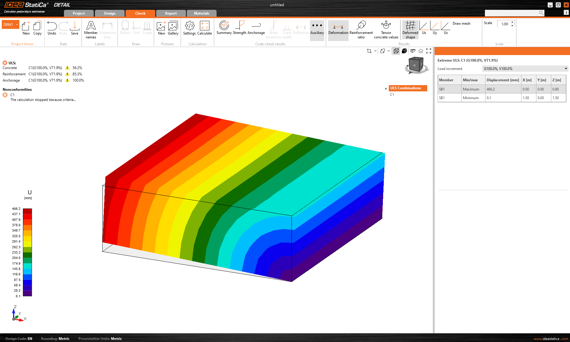
Le pourcentage de la charge transférée est affiché. De plus, la déformation extrême est affichée dans les résultats auxiliaires.
Solution de contournement : Il est recommandé de calculer d'abord tout modèle avec le multiplicateur de taille de maillage par défaut réglé sur une valeur élevée (4-5). Ce multiplicateur se trouve dans Paramètres -> Paramètres du maillage. Le calcul sera rapide et vous pourrez voir si le renversement est le problème ou non.
Il est nécessaire de vérifier si le poids propre du bloc en béton est inclus, car il peut empêcher le renversement du modèle. Notez que lors de l'import depuis l'application Connection, le poids propre n'est pas automatiquement saisi dans le modèle — voir le texte ci-dessous pour plus de détails.
Limitations de l'import depuis Connection
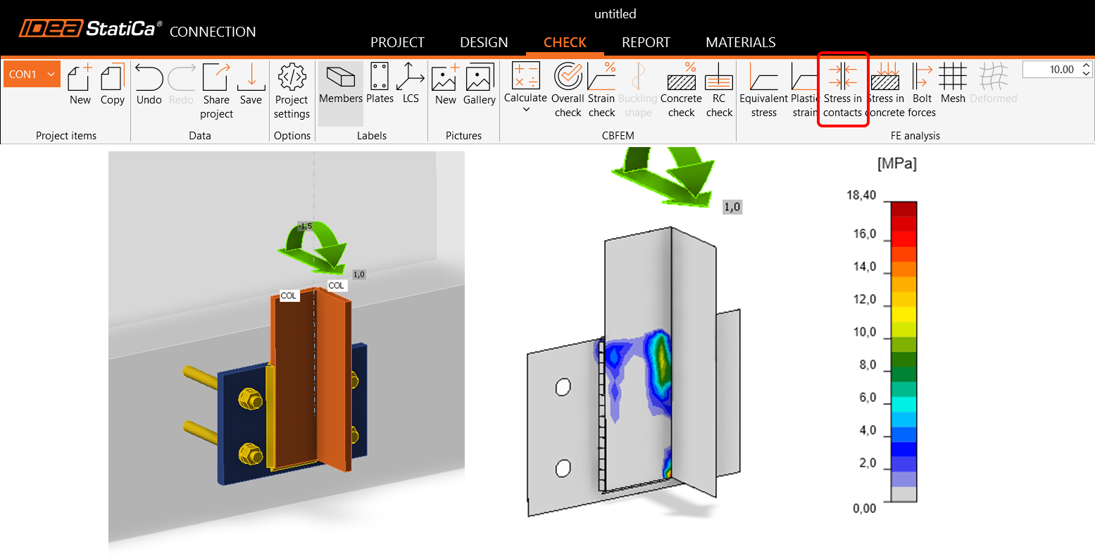
Contacts
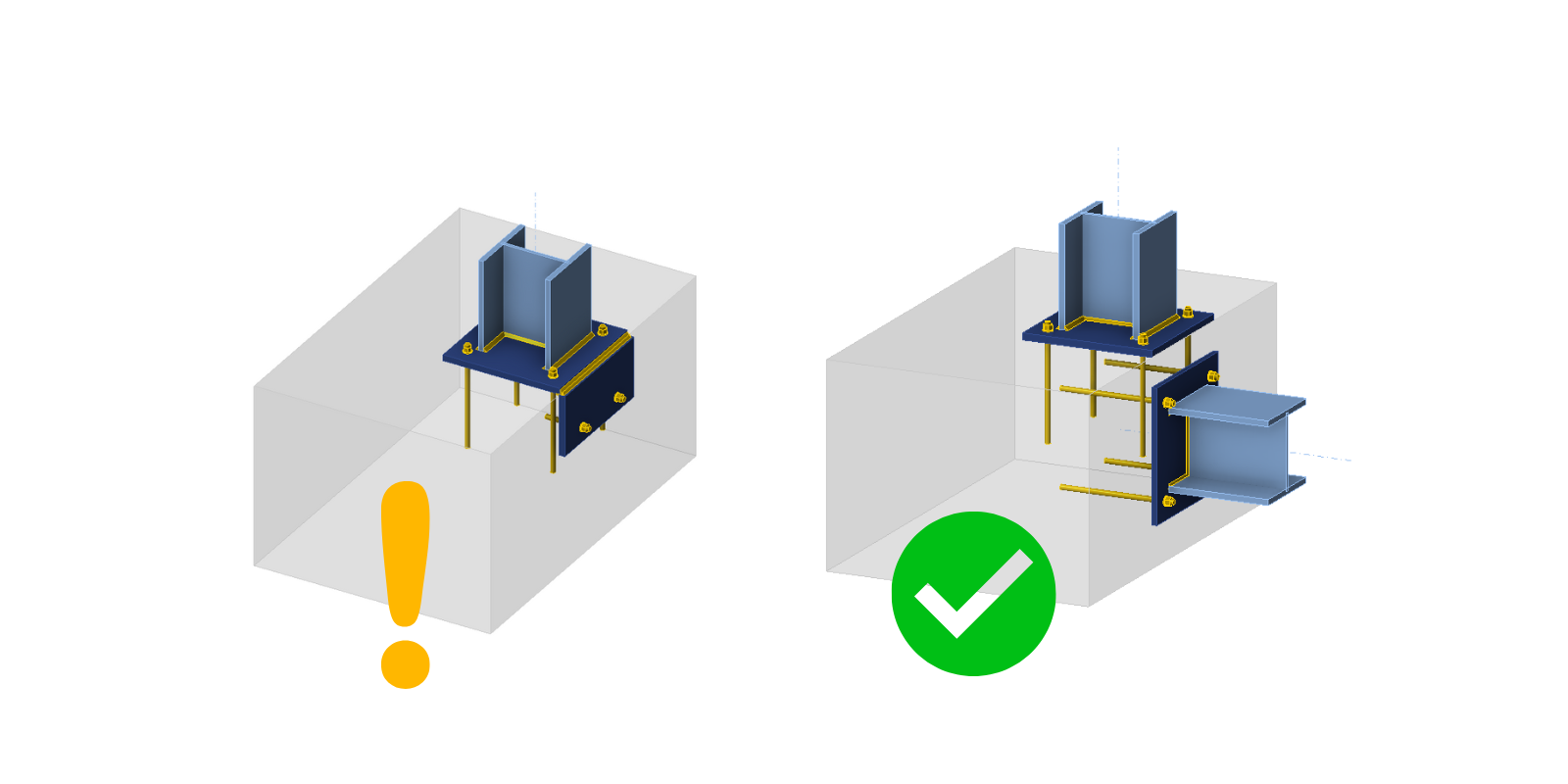
En général, l'import des efforts agissant sur la platine de base par contact avec une autre platine acier n'est pas pris en charge. Cela s'applique aux deux types de contacts : bord-surface et surface-surface. En savoir plus dans cet article.
Ancrage par élément
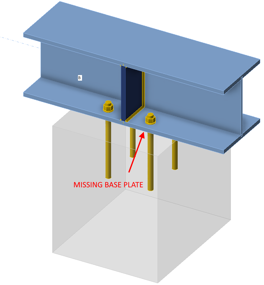
Seuls les modèles ancrés via la platine de base peuvent être correctement importés dans l'application Detail. Pour les modèles où les éléments sont connectés directement aux blocs en béton, la platine de connexion de l'élément avec les ancrages est importée sans charges.
Le poids propre n'est pas ajouté automatiquement
Le poids propre n'est pas calculé/ajouté automatiquement. Il doit être inclus manuellement dans le projet pour Detail. Cela peut principalement affecter la vérification de l'ancrage aux fondations, où le fait de ne pas prendre en compte le poids propre pourrait conduire au renversement de la fondation, comme mentionné dans le paragraphe ci-dessus.
Types d'ancrage non pris en charge pour l'export
Les ancrages avec crochet ne sont pas pris en charge dans Detail. Une rondelle sera utilisée à la place dans le fichier exporté.
La rondelle est modélisée comme un élément plaque-coque directement attaché à la tige d'ancrage, transférant la charge au béton exclusivement par contact en compression. La platine elle-même est modélisée de manière linéaire, sans plasticité, et n'est pas soumise à des vérifications de résistance. Étant donné que la tige possède une adhérence nulle, la totalité de la charge est transférée au béton par la rondelle. Plus d'informations sur les types d'ancrages sont disponibles dans l'article : Définition d'un ancrage unique.
Combinaisons non prises en charge pour les types d'ancrages
L'application Detail ne prend pas en charge la combinaison de goujons à tête ou de ferraillage avec d'autres types d'ancrages. Ces types d'ancrages ne seront pas inclus dans le résultat. Plus d'informations sur les options de platines sont disponibles dans l'article : Options des platines d'ancrage.
Combinaison des charges importées et des charges saisies par l'utilisateur
Les charges importées et les charges saisies par l'utilisateur ne peuvent pas être combinées dans un même modèle. En raison des raisons décrites dans les bases théoriques. Les ancrages sont importés déconnectés des platines de base. Si vous créez un cas de charge défini par l'utilisateur, il est évident que la charge ne sera pas transférée correctement.
Solution de contournement : Copiez l'élément de projet importé, supprimez toutes les charges importées, interconnectez tous les ancrages avec la platine de base, puis vous pouvez saisir votre cas de charge défini par l'utilisateur.
Plusieurs blocs en béton
Un seul bloc en béton est pris en charge dans Detail. Cependant, le bloc en béton peut être modifié à l'aide du volume négatif, du plan de coupe et de l'opération de coupe. Il est donc possible de modéliser des formes plus complexes telles que des socles, des extensions de semelles filantes, des ancrages à proximité d'ouvertures, etc.
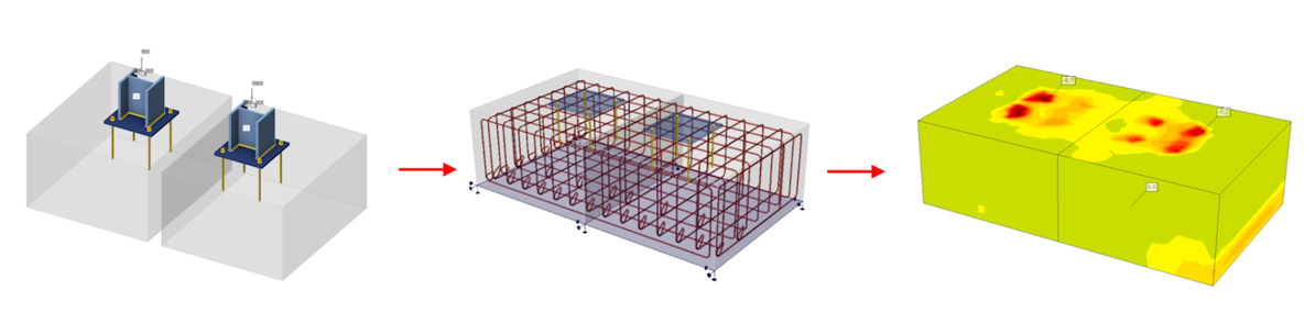
Il est également possible d'importer deux blocs en béton indépendants depuis Connection, qui sont importés dans Detail comme deux entités de modèle pouvant être modifiées ultérieurement à l'aide de l'opération de coupe.
Plus d'une platine de base dans un seul bloc
L'export de plusieurs platines de base dans un seul bloc est pris en charge, bien qu'il ne soit pas recommandé d'importer ce que l'on appelle l'ancrage en rive.
Dans l'application Connection, le béton est modélisé de manière simplifiée à l'aide du modèle de Winkler. En revanche, le modèle de la partie acier au-dessus du bloc en béton est modélisé en détail, incluant la plasticité des matériaux. Pour une vérification plus détaillée du béton armé sous la platine de base, il est possible d'exporter la platine de base, les ancrages et les charges vers l'application Detail. Là, le béton est modélisé de manière plastique.
Les ancrages sont exportés axialement déconnectés, et la charge entre eux est remplacée par une paire de forces égales et opposées (précisément en raison du manque de rigidité de la partie acier au-dessus de la platine de base). Par conséquent, il n'est pas possible que les efforts axiaux dans les ancrages changent si la couche de recouvrement dans le coin du bloc en béton devient plastique. De même, les soudures des platines de base sont exportées déconnectées, la connexion étant remplacée par des forces égales et opposées. Par conséquent, il ne peut y avoir aucun changement de contrainte sur la soudure en cas de plastification du coin en béton.
Il s'ensuit qu'après l'export, bien que toutes les forces agissant sur les platines de base soient en équilibre, les conditions de déformation ne seront pas satisfaites.
Ceci s'applique à la version actuelle 25.1.2. Cela peut différer dans les versions précédentes, car nous travaillons progressivement à la suppression de ces limitations. Vous pouvez trouver plus d'informations sur chaque version dans les notes de version.