
Code et paramètres de calcul dans RCS
Données du projet
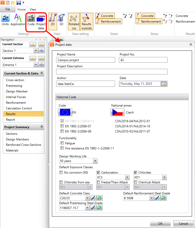
Commençons par les paramètres des données du projet. Vous pouvez accéder au tableau depuis le ruban supérieur -> barre d'outils Paramètres. L'une des choses à définir ici est l'information de base sur le projet, comme le nom du projet, le numéro, la description, l'auteur et la date. Ces informations seront ensuite transmises au rapport automatique.
Une autre saisie possible ici est le paramétrage des valeurs par défaut pour la norme nationale. Vous pouvez définir les normes et l'annexe nationale pour le projet, ainsi que les fonctionnalités, la durée de vie de calcul, les classes d'exposition et les nuances de matériaux.
Paramètres de code et de calcul
Ensuite, il y a les paramètres de code et de calcul, où vous pouvez parcourir les chapitres de la norme utilisée et modifier les valeurs par défaut des coefficients, limites ou conditions.
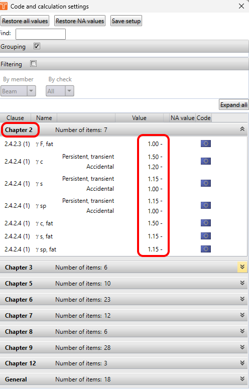
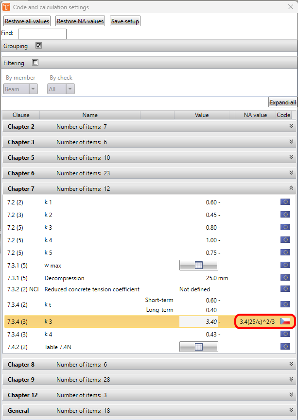
Si l'annexe nationale est sélectionnée, vous verrez le drapeau de l'annexe à côté des valeurs qui diffèrent de l'Eurocode général. La nouvelle valeur ou, par exemple, l'équation pour le calcul automatique sera également affichée, comme le montre la figure suivante.
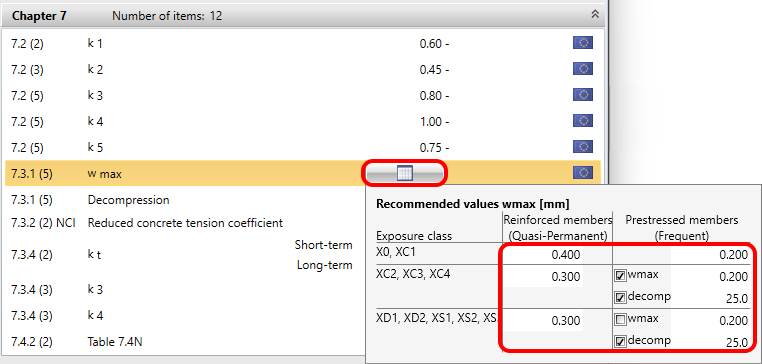
Il peut également y avoir une saisie sous forme de tableau, qui peut bien entendu être ajustée de la même manière. Voir l'exemple avec le tableau de la largeur des fissures dans la figure suivante.
Le dernier onglet, mais non des moindres, est Général. Il contient les paramètres généraux du calcul.
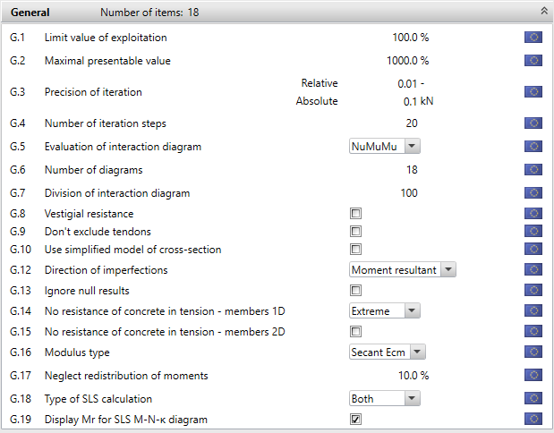
Passons-les en revue :
G.1 - Valeur limite d'exploitation - La valeur maximale du taux de travail de la section transversale ne doit pas nécessairement être de 100 %. Vous pouvez la modifier à l'aide de ce paramètre.
G.2 - Valeur maximale affichable - Ici, vous pouvez modifier la valeur maximale du taux de travail.
G.3 et G.4 - Précision de l'itération et Nombre de pas d'itération - Vous pouvez également influencer le processus d'itération. Cela peut contribuer à accélérer le calcul.
G.5 - Évaluation du diagramme d'itération - Ce point est décrit dans l'article suivant, au chapitre Capacité N-M-M : Résultats ELU dans RCS
G.6 - Nombre de diagrammes - Nombre de sections verticales à travers la surface d'interaction autour des axes verticaux. En augmentant ce nombre, vous pouvez accroître la précision du diagramme d'interaction. Pour en savoir plus, consultez l'article suivant : Flexion
G.7 - Division du diagramme d'interaction - De même, en augmentant ce nombre, vous pouvez accroître la précision du diagramme d'interaction.
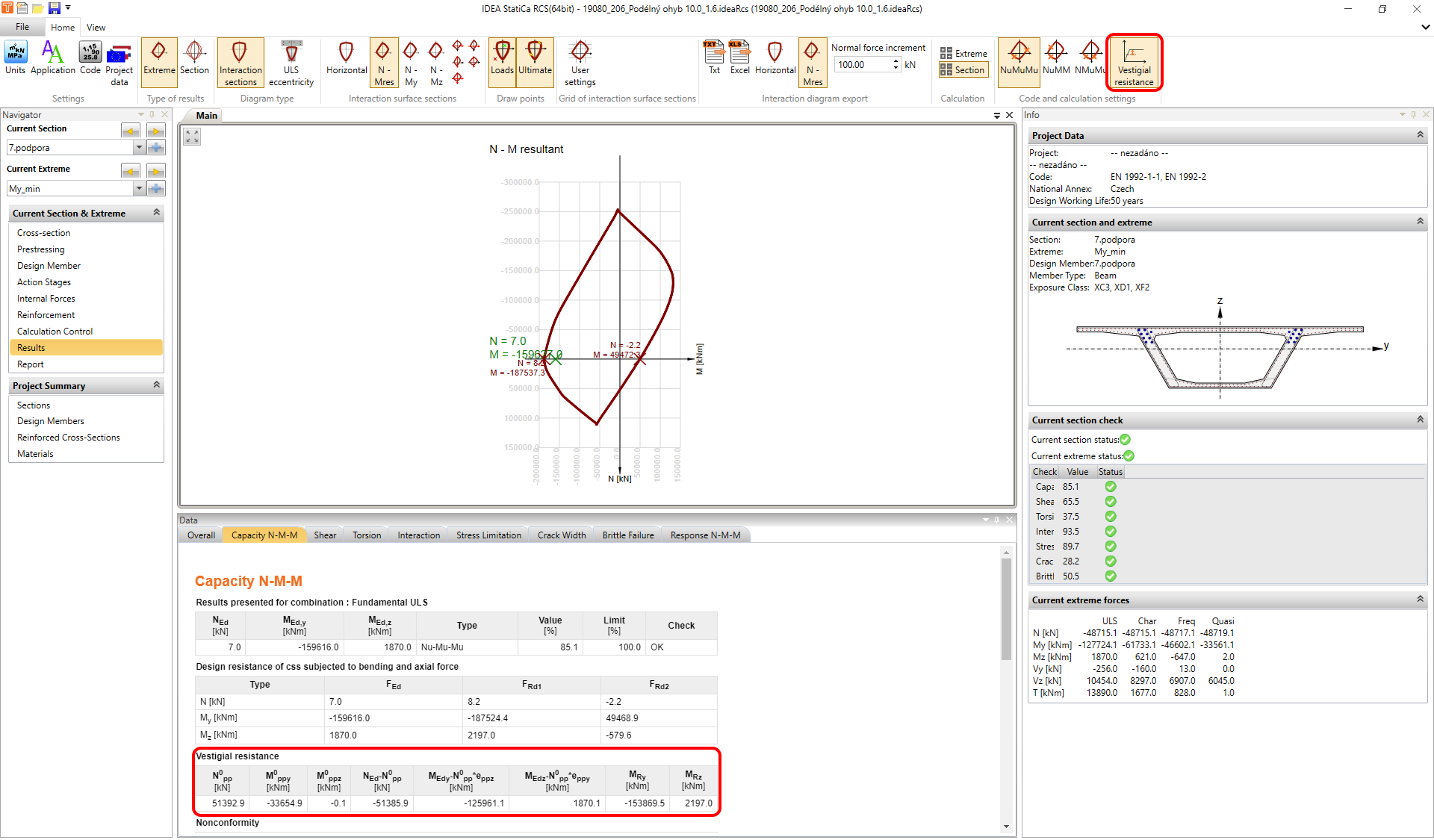
G.8 - Résistance résiduelle - Valable uniquement pour les sections transversales précontraintes. Si elle est DÉSACTIVÉE - Le membre gauche de la condition de fiabilité contient uniquement la charge extérieure. Le membre droit est la résistance, qui comprend les effets primaires résultant de la force de précontrainte à la décompression et l'effet de la résistance résiduelle du ferraillage de précontrainte. Si elle est ACTIVÉE - Un tableau supplémentaire est affiché, dans lequel le membre gauche de la condition de fiabilité contient la charge extérieure diminuée de l'effet primaire résultant de la force de précontrainte à la décompression. Le membre droit est la résistance, qui comprend uniquement l'effet de la résistance résiduelle du ferraillage de précontrainte.
G.9 - Ne pas exclure les câbles de précontrainte - Si cette option est activée, les câbles de précontrainte situés en dehors de la section transversale seront inclus dans le calcul.
G.10 - Utiliser un modèle simplifié - Vous pouvez utiliser cette option pour accélérer votre calcul.
G.12 - Direction de l'imperfection - L'effet est décrit dans l'article suivant : Effet du second ordre dans l'application RCS
G.14 - Pas de résistance du béton en traction - éléments 1D
- Toujours - L'hypothèse selon laquelle le béton ne résiste pas à la traction sera appliquée dans toutes les vérifications ELS pour toutes les combinaisons de toutes les sections et leurs extrêmes.
- Section - Dans le cas où la valeur de calcul supérieure ou inférieure des efforts intérieurs de l'une des combinaisons ELS entraîne une contrainte dans le béton supérieure à la résistance en traction du béton, l'hypothèse selon laquelle le béton ne résiste pas à la traction sera appliquée dans toutes les vérifications ELS pour tous les extrêmes de la section courante. Les hypothèses pour les vérifications ELS dans les combinaisons des autres sections ne seront pas affectées.
- Extrême - Dans le cas où la valeur de calcul supérieure ou inférieure des efforts intérieurs de l'une des combinaisons ELS entraîne une contrainte dans le béton supérieure à la résistance en traction du béton, l'hypothèse selon laquelle le béton ne résiste pas à la traction sera appliquée dans toutes les vérifications ELS pour l'extrême courant uniquement. Les hypothèses pour les vérifications ELS dans les autres extrêmes de la section courante ne seront pas affectées.
G.15 - Pas de résistance du béton en traction - éléments 2D - ACTIVÉ : la traction dans le béton pour les vérifications ELS est négligée. DÉSACTIVÉ : le calcul est effectué conformément à la norme.
G.16 - Type de module - Vous pouvez sélectionner le type de module d'élasticité utilisé pour les vérifications ELS à long terme
- Sécant Ecm
- Tangent Ec = 1,05*Ecm
G.17 - Négliger la redistribution des moments
G.18 - Type de calcul ELS - Ce paramètre vous permet de calculer uniquement les vérifications à long terme ou à court terme pour l'ELS
G19 - Afficher Mr pour le diagramme ELS M-N-κ