Check of steel connection components (CSA)
CBFEM method combines the advantages of the general finite element method and the standard component method. The stresses and internal forces calculated on the accurate CBFEM model are used in checks of all components.
Components are designed according to the Canadian standard (Canadian Institute of Steel Construction, CISC) S16-14 Design of steel structures and CSA A23.3 Design of concrete structures.
Code-check of steel plates according to Canadian standards
The resulting equivalent stress (HMH, von Mises) and plastic strain are calculated on plates. When the yield strength (multiplied by resistance factor for structural steel ϕ = 0.9, which is editable in Code setup) on the bilinear material diagram is reached, the check of the equivalent plastic strain is performed. The limit value of 5 % is suggested in Eurocode (EN1993-1-5 App. C, Par. C8, Note 1), this value can be modified in Code setup, but verifications were done for the recommended value.
The plate element is divided into five layers, and elastic/plastic behavior is investigated in each of them. The program shows the worst result from all of them. The CBFEM method can provide stress a little bit higher than yield strength. The reason is the slight inclination of the plastic branch of the stress-strain diagram, which is used in the analysis to improve the stability of the interaction calculation. This is not a problem for practical design. The equivalent plastic strain is exceeded at higher stress, and the joint does not satisfy anyway.
Code-check of welds according to Canadian standards
Fillet welds are checked according to S16-14 - Chapter 13. The strength of CJP groove welds is assumed the same as the base metal and is not checked.
Fillet welds
The resistance for direct shear and tension or compression induced shear is designed according to S16-14 – 13.13.2.2. Plastic redistribution in weld material is applied in Finite Element Modelling.
\[ V_r = 0.67 \phi_w A_w X_u (1+0.5 \sin^{1.5} \theta ) M_w \]
where:
- ϕw = 0.67 – resistance factor for weld metal, editable in Code setup
- Aw – area of effective weld throat
- Xu – ultimate strength as rated by the electrode classification number
- θ – angle of axis of weld segment with respect to the line of action of applied force (e.g., 0° for a longitudinal weld and 90° for a transverse weld)
- \( M_w = \frac{0.85+\theta_1 / 600}{0.85+\theta_2 / 600} \) – strength reduction factor for multi-orientation fillet welds; equals to 1.0 in IDEA and the resistance of multi-orientation welds is determined by FEA where the most stressed element is assessed
- θ1 – orientation of the weld segment under consideration
- θ2 – orientation of the weld segment in the joint that is nearest to 90°
Base metal capacity at the fusion face:
\[ V_r = 0.67 \phi_w A_m F_u \]
where:
- Am = z L – area of the fusion face
- z – leg size of the weld
- L – length of the weld
- Fu – specified tensile strength
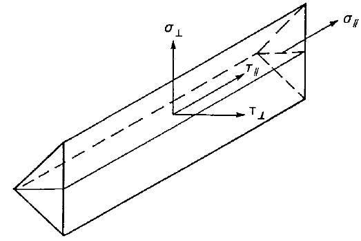
The weld diagrams show stress according to the following formulas:
If base metal is deactivated (matching electrode is used):
\[ \sigma = \frac{\sqrt{ \sigma_{\perp}^2 + \tau_{\perp}^2 + \tau_{\parallel}^2 }}{1+0.5 \sin^{1.5}{\theta}} \]
If base metal is activated (matching electrode is not used):
\[ \sigma = \max \left \{ \frac{\sqrt{ \sigma_{\perp}^2 + \tau_{\perp}^2 + \tau_{\parallel}^2 }}{1+0.5 \sin^{1.5}{\theta}}, \, \frac{\sqrt{ \sigma_{\perp}^2 + \tau_{\perp}^2 + \tau_{\parallel}^2 }}{\sqrt{2} F_u / X_u} \right \} \]
CJP groove welds
The resistance of Complete Joint Penetration (CJP) groove welds is assumed as that of the base metal.
Code-check of bolts and preloaded bolts according to Canadian standards
The forces in bolts including prying forces are determined by finite element analysis. The bolt resistances are checked by S16 – Chapter 13.
Bolts
Tensile strength of bolts
The tensile resistance of a bolt is assessed according to Clause 13.12.1.3 and taken as:
\[ T_r = 0.75 \phi_b A_b F_u \]
where:
- ϕb = 0.8 – resistance factor for bolts, editable in Code setup
- Ab – cross-sectional area of a bolt based on its nominal diameter
- Fu – specified minimum tensile strength for a bolt
When the bolt threads are intercepted by a shear plane, the shear resistance is taken as 0.7 Vr.
Shear strength of bolts
The shear resistance of a bolt is assessed according to Clause 13.12.1.2. Each shear plane of a bolt is checked separately. It is taken as:
\[ V_r=0.6 \phi_b A_b F_u \]
where:
- ϕb = 0.8 – the resistance factor for bolts, editable in Code setup
- Ab – cross-sectional area of a bolt based on its nominal diameter
- Fu – specified minimum tensile strength for a bolt
When the bolt threads are intercepted by a shear plane, the shear resistance is taken as 0.7 Vr.
Combined tension and shear in bearing type connection
The resistance of a bolt loaded by combined tension and shear is assessed according to Clause 13.12.1.4 and taken as:
\[ \left ( \frac{V_f}{V_r} \right )^2 + \left ( \frac{T_f}{T_r} \right )^2 \le 1 \]
where:
- Vf and Tf are design shear force and tensile force acting on the bolt, respectively
- Vr and Tr are design shear resistance and tensile resistance of the bolt, respectively
Bearing strength in bolt holes
The resistance developed at the bolt in a bolted joint subjected to bearing and shear is assessed according to Clause 13.12.1.2 and taken as
Br = 3 ϕbr t d Fu for regular bolt holes
Br = 2.4 ϕbr t d Fu for slotted holes loaded perpendicular to these holes
where:
- ϕbr = 0.8 – resistance factor for the bearing of bolts on the steel
- t – thinner thickness of connected plates
- d – diameter of a bolt
- Fu – tensile strength of the connected material
Hole tear-out of a bolt
The resistance of hole tear-out of a bolt is checked for individual bolts according to Clause 13.11 as:
\[ T_r = \phi_u 0.6 A_{gv} \frac{F_y+F_u}{2} \]
where:
- ϕu = 0.75 – resistance factor for structural steel
- Agv = 2 ∙ l ∙ t – gross area in shear
- Fy – yield strength of the connected material
- Fu – tensile strength of the connected material
- l – distance from the centreline of the bolt to the edge in the direction of the shear force
- t – thickness of the connected material
For steel grades with Fy > 460 MPa, (Fy + Fu) / 2 shall be replaced with Fy in the determination of Tr.
Bolts in slip-critical connections
The slip resistance of a bolted joint is assessed according to Clause 13.12.2 as
Vs = 0.53 cs ks Ab Fu
where:
- cs – coefficient determined according to ks and bolt grade:
- for ks < 0.52 class A cs = 1.00 (A325) or 0.92 (A490) or 0.78 (other)
- for ks ≥ 0.52 class B cs = 1.04 (A325) or 0.96 (A490) or 0.81 (other)
- ks – friction coef. editable in Code setup which should be set according to Table 3 in S16-14; equals 0.3 for class A or 0.52 for class B
- Ab – cross-sectional area of a bolt based on its nominal diameter
- Fu – specified minimum tensile strength for a bolt
When slotted holes are used in slip-critical connections, Vs = 0.75 ∙ 0.53 cs ks Ab Fu.
A bolt subjected to both tension and shear must satisfy the following relationship:
\[ \frac{V_f}{V_s}+1.9\frac{T}{A_b F_u} \]
where:
- Vf and Tf are the design shear force and the tensile force acting on the bolt, respectively
Clause 13.12.2 states that the resistances of the connection as specified in Clause 13.12.1 shall be checked. The user should, therefore, check the state after slip occurs, i.e. change the shear force transfer of bolts from “Friction” to “Bearing – tension and shear interaction”.
Detailing
In the detailing of bolted connections, the minimum pitch and minimum edge distance are checked according to S16-14 – 22.3. Minimum pitch (2.7 d – editable in Code setup) and minimum edge distance (1.25 d) are checked.
Code-check of concrete block according to Canadian standards
The concrete below the base plate is simulated by Winkler subsoil with uniform stiffness, which provides the contact stresses. The average stress at the loaded area in contact with the base plate is used for compressive check.
Concrete in compression
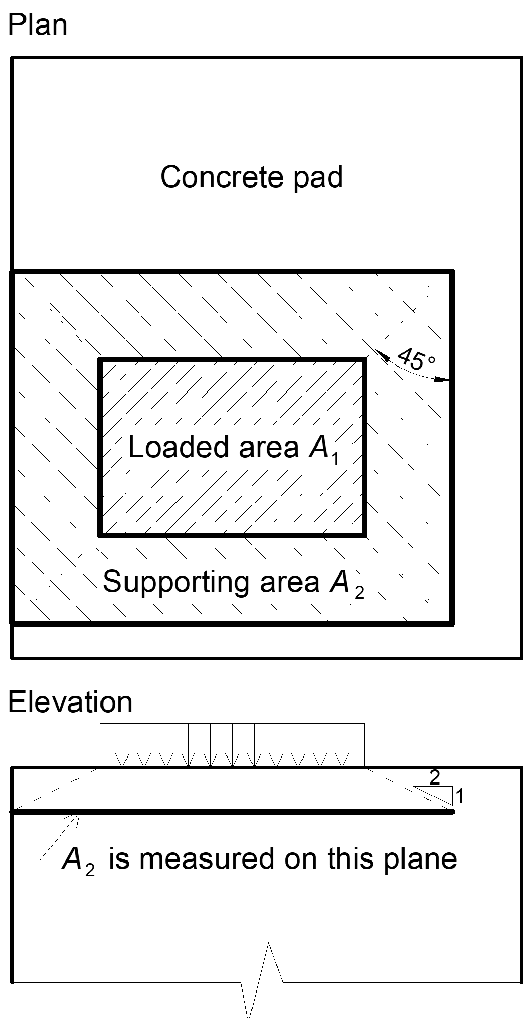
The concrete design bearing strength in compression is determined in accordance with S16-14 – 25.3.1 and CSA A23.3 – 10.8. When the supporting surface of the concrete is larger than the base plate the design bearing strength is defined as
\[ f_{p,(max)} = 0.85 \phi_c f'_c \sqrt{\frac{A_2}{A_1}} \le 1.7 \phi_c f'_c \]
where:
- ϕc=0.65 – resistance factor for concrete
- f'c – concrete compressive strength
- A1 – base plate area in contact with a concrete surface (upper surface area of the frustum)
- A2 – concrete supporting surface (geometrically similar lower area of the frustum having its slopes of 1 vertical to 2 horizontal)
The assessment of concrete in the bearing is as follows:
σ ≤ fp(max)
where:
- σ – average compressive stress under the base plate
Transfer of shear forces
Shear loads can be transferred via one of these options:
- Shear lug,
- Friction,
- Anchor bolts.
Shear lug
Shear loads are considered to be transferred only via shear lug. Concrete bearing is not checked in software and should be checked by the user elsewhere. Shear lug and welds are checked using FEM and weld components.
Friction
In the case of compressive force, the shear loads can be transferred via friction between a concrete pad and a base plate. The friction coefficient is editable in the Code setup.
Anchor bolts
If the shear load is transferred via anchor bolts only, the shear force acting on each anchor is determined by FEA and anchor bolts are assessed according to ACI 318-14 as described in the following chapters.
Code-check of anchors according to Canadian standards
The forces in anchors including prying forces are determined by finite element analysis, but the resistances are checked using code provisions of A23.3 - Annex D.
Anchor rods are designed according to A23.3-14 – Annex D. The following resistances of anchor bolts are evaluated:
- Steel strength of anchor in tension Nsar,
- Concrete breakout strength in tension Ncbr,
- Concrete pullout strength Npr,
- Concrete side-face blowout strength Nsbr,
- Steel strength of anchor in shear Vsar,
- Concrete breakout strength in shear Vcbr,
- Concrete pryout strength of anchor in shear Vcpr.
The concrete condition may be chosen by user as cracked or non-cracked. The type of anchors (cast-in headed with circular or rectangular washers, straight anchors) is selected by user, the pullout strength and side-face blowout strength are checked in the software only for headed anchors.
Following checks of anchors loaded in tension are not provided and should be checked using information in relevant Technical Product Specification (based on the 5 percent fractile of tests):
- Pull-out failure of fastener (for post-installed mechanical anchors) – CSA A23.3-14: D.6.3,
- Bond strength of adhesive anchor (for post-installed bonded anchors) – CSA A23.3-14: D.6.5.
Anchors shall satisfy the required edge distances, spacings, and thicknesses to preclude splitting failure as required by CSA A23.3-14: D.9.
Steel resistance of anchor in tension
Steel strength of anchor in tension is determined according to CSA A23.3-14 – D.6.1 as
Nsar = Ase,N ϕs futa R
where:
- ϕs = 0.85 – steel embedment material resistance factor for reinforcement
- Ase,N – effective cross-sectional area of an anchor in tension
- futa ≤ min (860 MPa, 1.9 fya) – specified tensile strength of anchor steel
- fya – specified yield strength of anchor steel
- R = 0.8 – resistance modification factor as specified in CSA A23.3.-14 – D.5.3
Concrete breakout resistance of anchor in tension
Concrete breakout strength is designed according to the Concrete Capacity Design (CCD) in CSA A23.3-14 – D.6.2. In the CCD method, the concrete cone is considered to be formed at an angle of approximately 34° (1 vertical to 1.5 horizontal slope). For simplification, the cone is considered to be square rather than round in plan. The concrete breakout stress in the CCD method is considered to decrease with an increase in the size of the breakout surface.
\[ N_{cbrg} = \frac{A_{Nc}}{A_{Nco}} \psi_{ed,N} \psi_{ec,N} \psi_{c,N} N_{br} \]
where:
- ANc – concrete breakout cone area for a group of anchors loaded by the tension that creates a common concrete cone
- ANco = 9 hef2 – concrete breakout cone area for single anchor not influenced by concrete edges
- \( \psi_{ed,N} = \min \left ( 0.7+\frac{0.3 c_{a,min}}{1.5 h_{ef}}, \, 1 \right ) \)– modification factor for edge distance
- ca,min – the smallest distance from the anchor to the edge
- hef – depth of embedment; according to A23.3-14 – D.6.2.3, the effective embedment depth hef is reduced to \( h_{ef} = \max \left ( \frac{c_{a,max}}{1.5}, \, \frac{s}{3} \right ) \) if anchors are located less than 1.5 hef from three or more edges
- \( \psi_{ec,N} = \frac{1}{1+\frac{2e'_N}{3 h_{ef}}} \) – modification factor for eccentrically loaded group of anchors
- e'N – tension load eccentricity with respect to the center of gravity of anchors loaded by tension and creating a common concrete cone
- Ψc,N – modification factor for concrete conditions; Ψc,N = 1 for cracked concrete, Ψc,N = 1.25 for non-cracked concrete
- \( N_{br} = k_c \phi_c \lambda_a \sqrt{f'_c} h_{ef}^{1.5} R \) – basic concrete breakout strength of a single anchor in tension in cracked concrete; for cast-in headed anchors and 275 mm ≤ hef ≤ 625 mm, \( N_{br} = 3.9 \phi_c \lambda_a \sqrt{f'_c} h_{ef}^{5/3} R \)
- ϕc=0.65 – resistance factor for concrete
- kc=10 for cast-in anchors
- s – spacing between anchors
- ca,max – maximum distance from an anchor to one of the three close edges
- λa = 1 – is modification factor for lightweight concrete
- f'c – concrete compressive strength [MPa]
- R = 1 – resistance modification factor as specified in CSA A23.3 – D.5.3
According to A23.3-14 – D.6.2.8, in case of headed anchors, the projected surface area ANc is determined from the effective perimeter of the washer plate, which is the lesser value of da + 2 twp or dwp, where:
- da – anchor diameter
- dwp – washer plate diameter or edge size
- twp – washer plate thickness
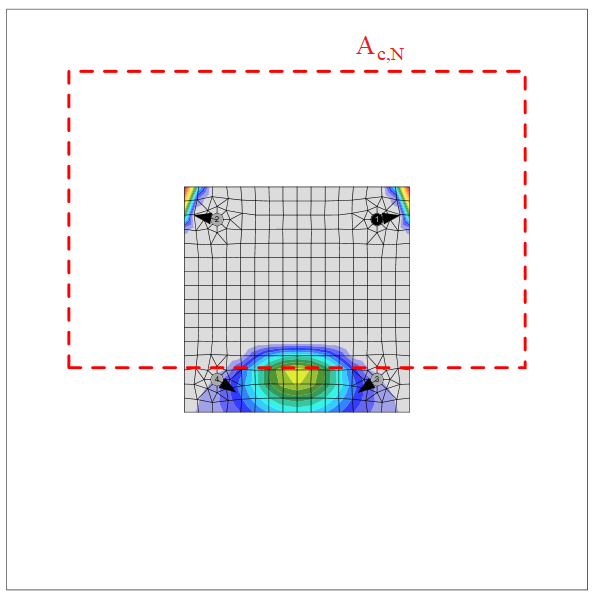
The group of anchors is checked against the sum of tensile forces in anchors loaded in tension and creating a common concrete cone.
The concrete breakout cone area for group of anchors loaded by tension that create common concrete cone, Ac,N, is shown by red dashed line.
According to CSA A23.3-14 – D.6.2.9, where anchor reinforcement is developed in accordance with Clause 12 of A23.3-14 on both sides of the breakout surface, the anchor reinforcement is presumed to transfer the tension forces, and concrete breakout strength is not evaluated (can be set in Code setup).
Concrete pullout resistance of anchor in tension
Concrete pullout strength of a headed anchor is defined in CSA A23.3-14 – D.6.3 as
Ncpr = Ψc,P Npr
where:
- Ψc,P – modification factor for concrete condition; Ψc,P = 1.0 for cracked concrete, Ψc,P = 1.4 for non-cracked concrete
- Npr = 8 Abrg ϕc f'c R for headed anchor
- Abrg – bearing area of the head of stud or anchor bolt
- ϕc = 0.65 – resistance factor for concrete
- da – anchor diameter
- f'c – concrete compressive strength
- R = 1 – resistance modification factor as specified in CSA A23.3 – D.5.3
Concrete pullout strength for other types of anchors than headed is not evaluated in the software and has to be specified by the manufacturer.
Concrete side-face blowout resistance
Concrete side-face blowout strength of headed anchor in tension is defined in CSA A23.3-14 – D.6.4 as:
\[ N_{sbr} = 13.3 c_{a1} \sqrt{A_{brg}} \phi_c \lambda_a \sqrt{f'_c} R \]
If ca2 for the single anchor loaded in tension is less than 3 ca1, the value of Nsbr is multiplied by the factor 0.5 ≤ (1+ ca2 / ca1) / 4 ≤ 1.
D.6.4.2 requires that a group of headed anchors with deep embedment close to an edge (hef > 2.5 ca1) and spacing between anchors less than 6 ca1 has the strength:
\[ N_{sbgr} = \left (1 + \frac{s} {6 c_{a1}} \right ) N_{sbr} \]
Only one reduction factor at a time is applied.
IDEA StatiCa always checks each anchor independently for side-face blowout strength and thus no anchor group of two anchors is assumed and rather the reduction factor is divided by two. This provides the same result if the tensile forces in each anchor are the same and a safe-sided assumption if the forces differ. The reduction factor used in IDEA StatiCa is:
\[ r_c = \min \left \{ \frac{1+\frac{c_{a2}}{c_{a1}}}{4}, \frac{1+\frac{s}{6\cdot c_{a1}}}{2} \right \} \]
\[0.5 \le r_c \le 1.0\]
where:
- ca1 – the shorter distance from an anchor to an edge
- ca2 – the longer distance, perpendicular to ca1, from an anchor to an edge
- Abrg – a bearing area of the head of stud or anchor bolt
- ϕc – resistance factor for concrete editable in Code setup
- f'c – concrete compressive strength
- hef – depth of embedment; according to A23.3-14 – D.6.2.3, the effective embedment depth hef is reduced to \( h_{ef} = \max \left ( \frac{c_{a,max}}{1.5}, \, \frac{s}{3} \right ) \) if anchors are located less than 1.5 hef from three or more edges
- s – spacing between anchors
- R = 1 – resistance modification factor as specified in CSA A23.3 – D.5.3
Steel resistance of anchor in shear
The steel strength in shear is determined according to A23.3 – D.7.1 as
Vsar = Ase,V ϕs 0.6 futa R
where:
- ϕs = 0.85 – steel embedment material resistance factor for reinforcement
- Ase,V – effective cross-sectional area of an anchor in shear
- futa – specified tensile strength of anchor steel but not greater than the smaller of 1.9 fya or 860 MPa
- R = 0.75 – resistance modification factor as specified in CSA A23.3 – D.5.3
If mortar joint is selected, steel strength in shear Vsa is multiplied by 0.8 (A23.3 –D.7.1.3).
The shear on lever arm, which is present in case of base plate with oversized holes and washers or plates added to the top of the base plate to transmit the shear force, is not considered.
Concrete breakout resistance of anchor in shear
Concrete breakout strength of an anchor in shear is designed according to A23.3 –D.7.2. The shear force acting on a base plate is assumed to be transferred by the anchors which are closest to the edge in the direction of the shear force. The direction of the shear force with respect to the concrete edge affects the concrete breakout strength according to FIB Bulletin 58 – Design of anchorages in concrete – Guide to good practice (2011). If concrete cones of anchors overlap, they create a common concrete cone. The eccentricity in shear is also taken into account.
\[ V_{cbr} = \frac{A_{Vc}}{A_{Vco}} \psi_{ec,V} \psi_{ed,V} \psi_{c,V} \psi_{h,V} \psi_{\alpha,V} V_{br} \]
where:
- AVc – projected concrete failure area of an anchor or group of anchors divided by number of anchors in this group
- AVco = 4.5 ca12 – projected concrete failure area of one anchor when not limited by corner influences, spacing or member thickness
- \( \psi_{ec,V} = \frac{1}{1+ \frac{2 e'_V}{3c_{a1}}} \) – modification factor for group of anchors loaded eccentrically in shear
- \( \psi_{ed,V} = 0.7 + 0.3 \frac{c_{a2}}{1.5 c_{a1}}\le1.0 \)– modification factor for edge effect
- Ψc,V – modification factor for concrete condition; Ψc,V = 1.0 for cracked concrete, Ψc,V = 1.4 for non-cracked concrete
- \( \psi_{h,V}=\sqrt{\frac{1.5c_{a1}}{h_a}} \ge 1 \)– modification factor for anchors located in a concrete member where ha < 1.5 ca1
- \( \psi_{\alpha,V} = \sqrt{\frac{1}{(\cos \alpha_V)^2+(0.5\sin \alpha_V)^2}} \) – modification factor for anchors loaded at an angle with the concrete edge (FIB Bulletin 58 – Design of anchorages in concrete – Guide to good practice, 2011)
- ha – height of a failure surface on the concrete side
- \( V_{br}=\min \left(0.58 \left (\frac{l_e}{d_a} \right )^{0.2} \sqrt{d_a} \phi_c \lambda_a \sqrt{f'_c} c_{a1}^{1.5} R, \, 3.75 \lambda_a \phi_c \sqrt{f'_c} c_{a1}^{1.5} R \right ) \)
- le = hef ≤ 8 da – load-bearing length of the anchor in shear
- da – anchor diameter
- f'c – concrete compressive strength
- ca1 – edge distance in the direction of load; according to Cl. 17.5.2.4, for a narrow member, c2,max < 1.5 c1 that is also deemed to be thin, ha < 1.5 c1, c'1 is used in previous equations instead of c1; the reduced c'1 = max (c2,max / 1.5, ha / 1.5, sc,max / 3)
- ca2 – edge distance in the direction perpendicular to load
- c2,max – largest edge distance in the direction perpendicular to load
- sc,max – maximum spacing perpendicular to direction of shear, between anchors within a group
- ϕc = 0.65 – resistance factor for concrete
- R = 1 – resistance modification factor as specified in CSA A23.3 – D.5.3
If both edge distances ca2 ≤ 1.5ca1 and ha ≤ 1.5 ca1, \( c_{a1} = \max \left ( \frac{c_{a2}}{1.5}, \, \frac{h_a}{1.5}, \, \frac{s}{3} \right ) \), where s is the maximum spacing perpendicular to direction of shear, between anchors within a group.
According to A23.3-14 – D.7.2.9, where anchor reinforcement is developed in accordance with A23.3-14 – Clause 12 on both sides of the breakout surface, the anchor reinforcement is presumed to transfer the shear forces and concrete breakout strength is not evaluated.
Concrete pryout resistance of an anchor in shear
Concrete pryout strength is designed according to A23.3 – D.7.3.
Vcpr = kcp Ncpr
where:
- kcp = 1.0 for hef < 65 mm, kcp = 2.0 for hef ≥ 65 mm
- Ncpr – concrete breakout strength – all anchors are considered to be in tension
According to CSA A23.3-14 – D.6.2.9, where anchor reinforcement is developed in accordance with Clause 12 of A23.3-14 on both sides of the breakout surface, the anchor reinforcement is presumed to transfer the tension forces and concrete breakout strength is not evaluated (can be set in Code setup).
Interaction of tensile and shear forces
Interaction of tensile and shear forces is assessed according to A23.3 – Figure D.18.
\[ \left ( \frac{N_f}{N_r} \right )^{5/3}+\left ( \frac{V_f}{V_r} \right )^{5/3} \le 1.0 \]
where:
- Nf and Vf – design forces acting on an anchor
- Nr and Vr – the lowest design strengths determined from all appropriate failure modes
Anchors with stand-off
Anchor with stand-off is designed as a bar element loaded by shear force, bending moment and compressive or tensile force. These internal forces are determined by the finite element model. The anchor is fixed on both sides, one side is 0.5×d below the concrete level, the other side is in the middle of the thickness of the plate. The buckling length is conservatively assumed as twice the length of the bar element. Plastic section modulus is used. The bar element is designed according to S16-14. Interaction of shear force is neglected because the minimum length of the anchor to fit the nut under the base plate ensures that the anchor fails in bending before the shear force reaches half the shear resistance, and the shear interaction is negligible (up to 7 %). Interaction of bending moment and compressive or tensile force is conservatively assumed as linear. Second-order effects are not taken into account.
Shear resistance (CSA S16-14 – 13.4.4):
Vr = ϕ ∙ 0.66 ∙ Av ∙ Fy
- Av = 0.844 ∙ As – the shear area
- As – the bolt area reduced by threads
- Fy – bolt yield strength
- ϕ – the resistance factor, the recommended value is 0.9
Tensile resistance (CSA S16-14 – 13.2)
Tr = ϕ ∙ As ∙ Fy
Compressive resistance (CSA S16-14 – 13.3.1)
\[ C_r = \frac{\phi A_s F_y}{\left (1+\lambda^{2n}\right )^{\frac{1}{n}}} \]
- \( \lambda = \sqrt{\frac{F_y}{F_e}} \) – anchor bolt slenderness
- \( F_e = \frac{\pi^2 E}{\left (\frac{KL}{r}\right )^2} \) – elastic buckling stress
- KL = 2 ∙ l – buckling length
- l – length of the bolt element equal to half the base plate thickness + gap + half the bolt diameter
- \( r = \sqrt{\frac{I}{A_s}} \) – radius of gyration of the anchor bolt
- \( I=\frac{\pi d_s^4}{64} \)– moment of inertia of the bolt
- n = 1.34 – parameter for compressive resistance
Bending resistance (CSA S16-14 – 13.5):
Mr = ϕ ∙ Z ∙ Fy
Z = ds3 / 6 – plastic section modulus of the bolt
Linear interaction:
\( \frac{N}{C_r}+\frac{M}{M_r} \le 1 \) ... for compressive normal force
\( \frac{N}{T_r}+\frac{M}{M_r} \le 1 \) ... for tensile normal force
- N – tensile (positive) or compressive (negative sign) factored force
- Cr – factored compressive (negative sign) resistance
- Tr – factored tensile (positive sign) resistance
- M – factored bending moment
- Mr – factored moment resistance
Detailing
The spacing between anchors should be greater than four times the anchor diameter according to A23.3-14 – D.9.2.
Edge distances to steel plate follow the rules of bolts, i.e. according to S16-14 – 22.3. minimum edge distance (1.25 d – editable in Code setup) is checked.
Steel joint classification according to Canadian standards
Joints are classified according to joint stiffness to:
- Rigid – joints with insignificant change of original angles between members,
- Semirigid – joints which are assumed to have the capacity to furnish a dependable and known degree of flexural restraint,
- Simple – joints which do not develop bending moments.
Canadian standard S14-16, Cl. 8.2 does not provide exact boundaries so the joints are classified according to the commentary in AISC 360-16, Cl. B3.4.
- Rigid – \( \frac{S_{j,ini} L_b}{E I_b} \ge 20 \)
- Semirigid – \( 2 < \frac{S_{j,ini} L_b}{E I_b} < 20 \)
- Simple – \( \frac{S_{j,ini} L_b}{E I_b} \le 2 \)
where:
- Sj,ini – initial stiffness of the joint; the joint stiffness is assumed linear up to the 2/3 of Mj,Rd
- Lb – theoretical length of the analyzed member
- E – Young's modulus of elasticity
- Ib – moment of inertia of the analyzed member
- Mj,Rd – joint design moment resistance
Capacity design according to Canadian standards
Capacity design is a part of seismic check and ensures that the joint has sufficient deformation capacity.
The objective of capacity design is to confirm a building undergoes controlled ductile behaviour in order to avoid collapse in a design-level earthquake. Plastic hinge is expected to appear in dissipative item and all non-dissipative items of the joint must be able to safely transfer forces due to the yielding in the dissipative item. The dissipative item is usually a beam in moment resisting frame but it may also be e.g. an end plate. The resistance factor is not used for dissipative items. Two factors are assigned to the dissipative item:
- Ry = 1.1 – overstrength factor – S16-14, Cl. 27.1.7; editable in materials
- Cpr = 1.1 – strain-hardening factor – S16-14, Cl. 27.2.2; it is recommended to apply for beam as a dissipative item in moment resisting frame
The material diagram is modified according to the following figure:
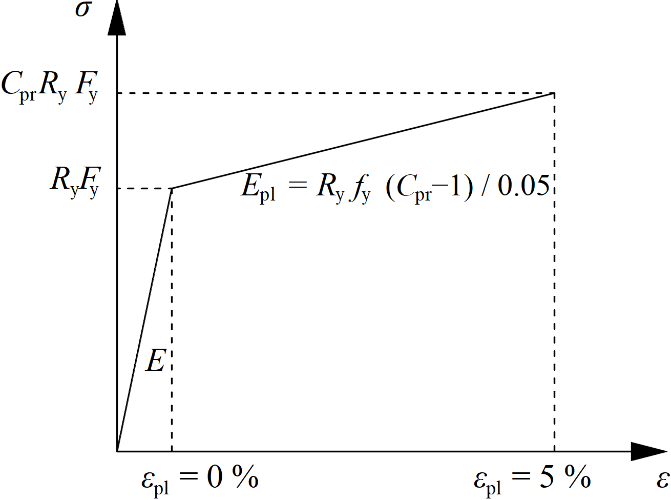
The increased strength of the dissipative item allows for the input of loads that cause the plastic hinge to appear in the dissipative item. In the case of moment resisting frame and beam as the dissipative item, the beam should be loaded by My = CprRyFyWpl,y and corresponding shear forceVz = –2 My,Ed / Lh, where:
- Fy – yield strength
- Wpl,y – plastic section modulus
- Lh – distance between plastic hinges on the beam
In case of asymmetric joint, the beam should be loaded by both sagging and hogging bending moments and their corresponding shear forces.
The plates of dissipative items are excluded from check.