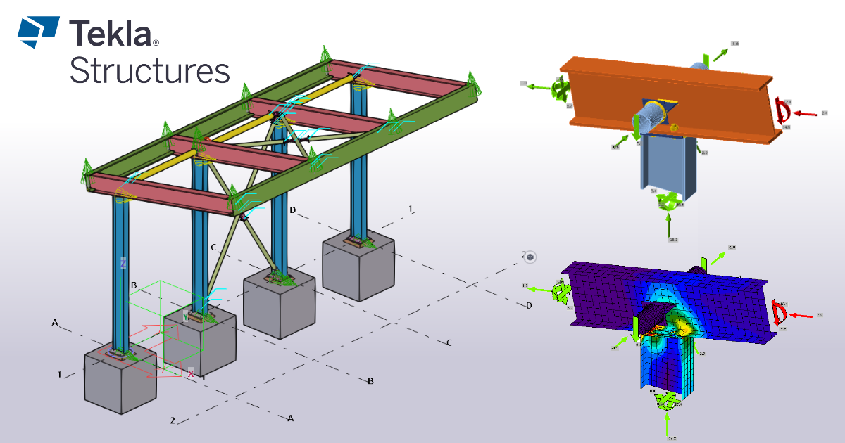
Enlace BIM de Tekla Structures para el diseño de uniones (EN)
Cómo activar el enlace
- Descargue e instale la última versión de IDEA StatiCa
- Asegúrese de que está utilizando una versión compatible de su solución FEA
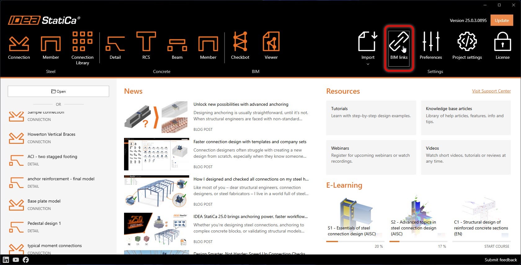
IDEA StatiCa integra enlaces BIM en su software FEA durante su instalación. Puede comprobar el estado e integrar más enlaces BIM ejecutando IDEA StatiCa y abriendo los enlaces BIM. Tenga en cuenta que algunos programas FEA requieren pasos adicionales para activar completamente su enlace BIM con IDEA StatiCa.
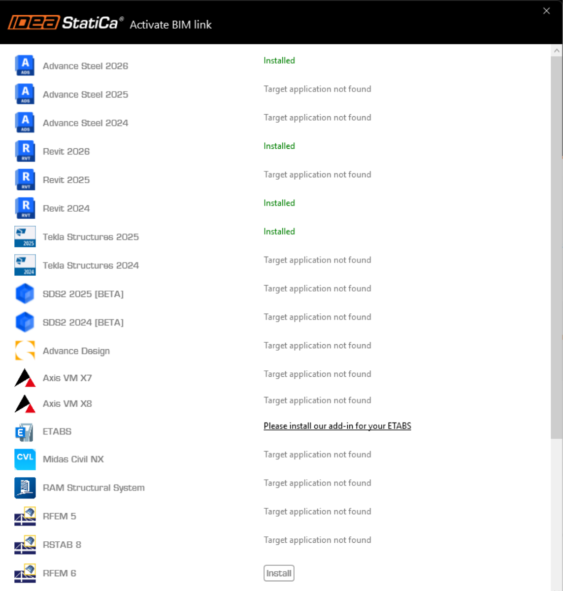
Puede aparecer una notificación "¿Desea permitir que esta aplicación realice cambios en su dispositivo?"; si es así, confirme con el botón Sí.
Al hacer clic en Instalar, el enlace BIM para el software seleccionado queda integrado. La pantalla también muestra el estado de los demás enlaces BIM.
Descargue el proyecto adjunto y ábralo en Tekla Structures, creado en el entorno Default (Trimble Downloads)
El enlace BIM está integrado automáticamente. Puede encontrarlo en la cinta superior en IDEA StatiCa -> Checkbot. Esto abrirá la aplicación Checkbot.

Seleccione la opción Nuevo con el tipo de proyecto Steel y el código de diseño EN. A continuación, seleccione Crear proyecto.
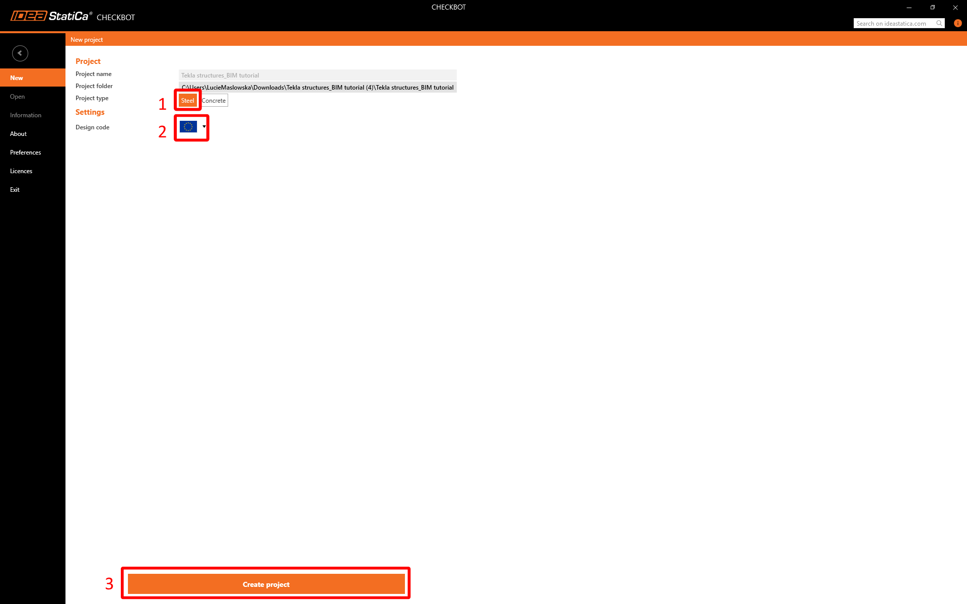
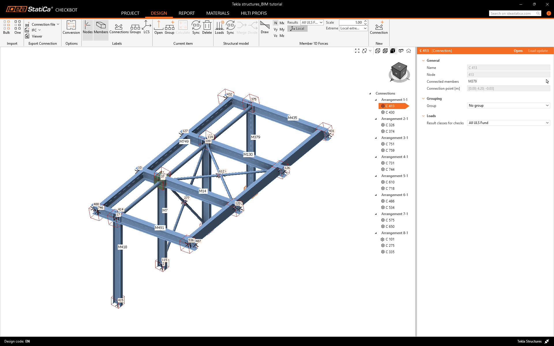
El nuevo proyecto de Checkbot está listo para importar uniones desde Tekla Structures.
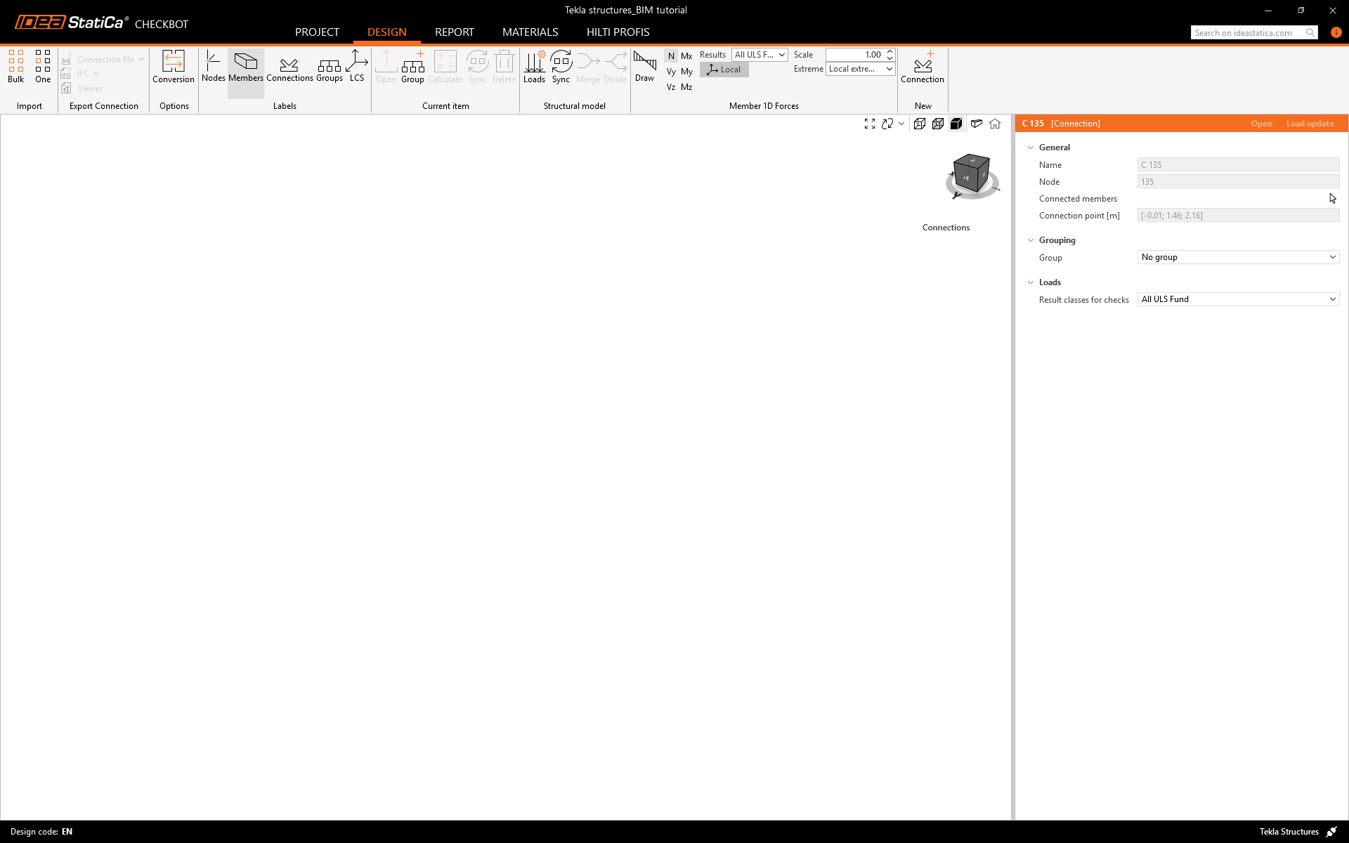
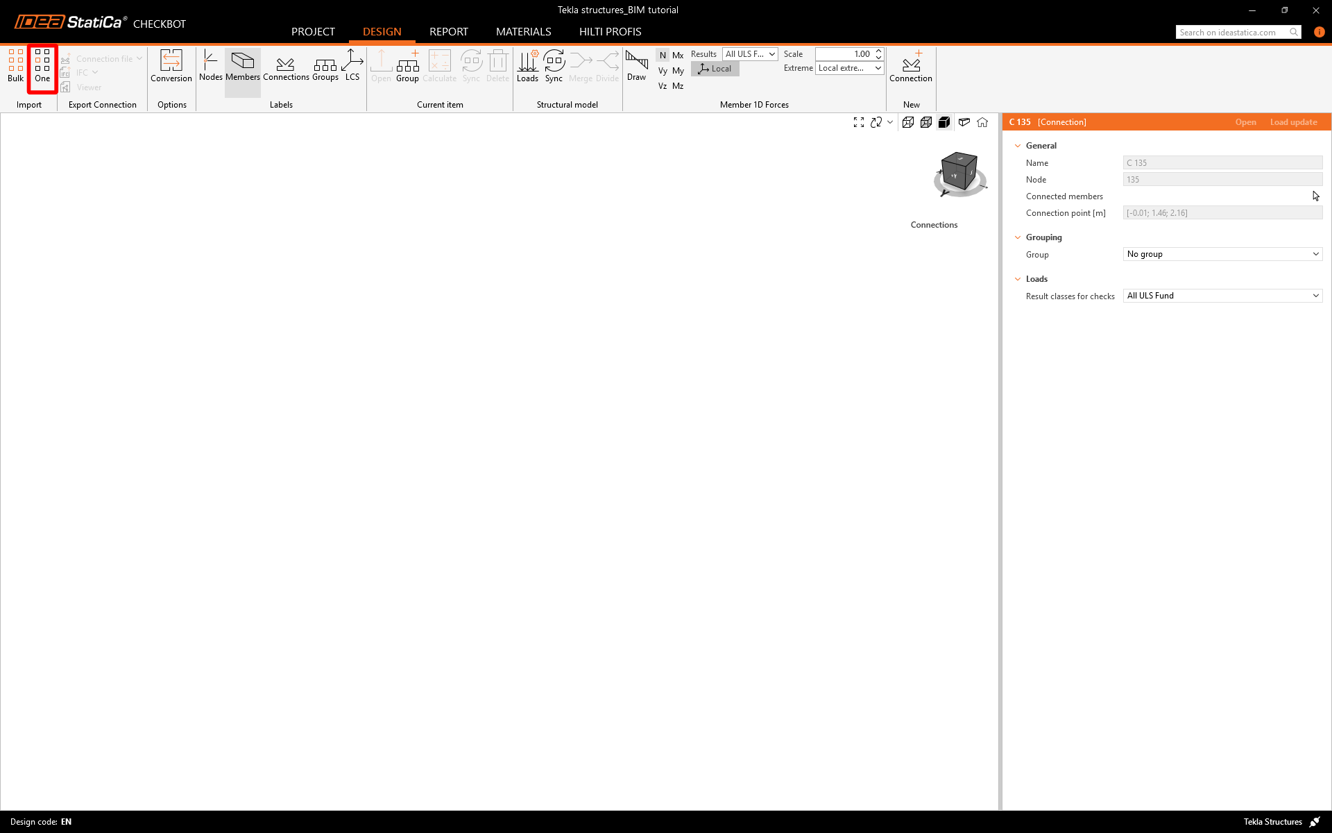
Importar
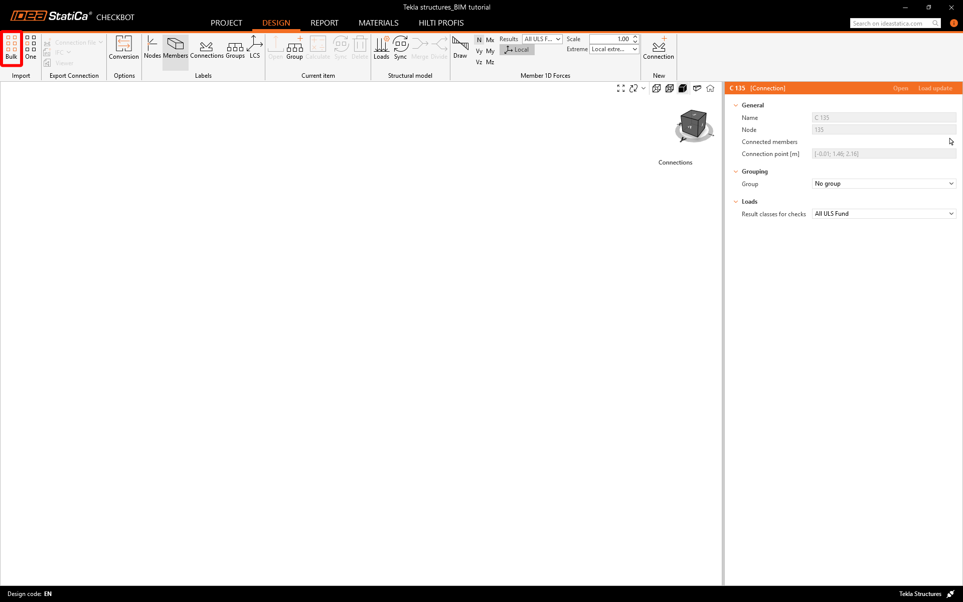
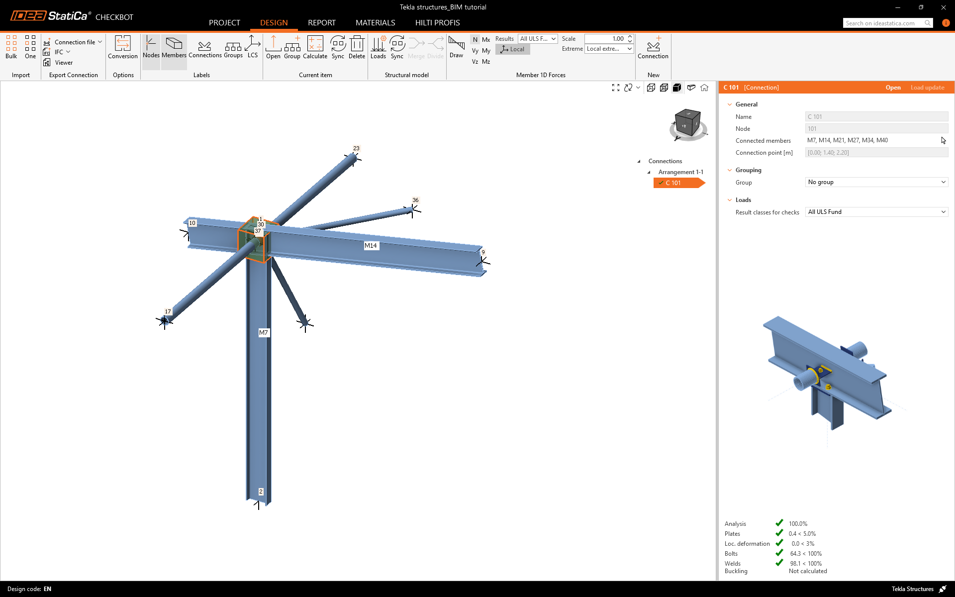
En la aplicación Checkbot, haga clic en el botón One en la cinta superior.
A continuación, en el modelo de Tekla Structures, siga estos pasos:
- Seleccione la posición del nodo que representa el centro de la unión.
- Seleccione los elementos relacionados con la junta. En este caso, se seleccionó en el orden de la secuencia de construcción: el primero se establecerá como el elemento portante en la aplicación Connection. Confirme con la barra espaciadora.
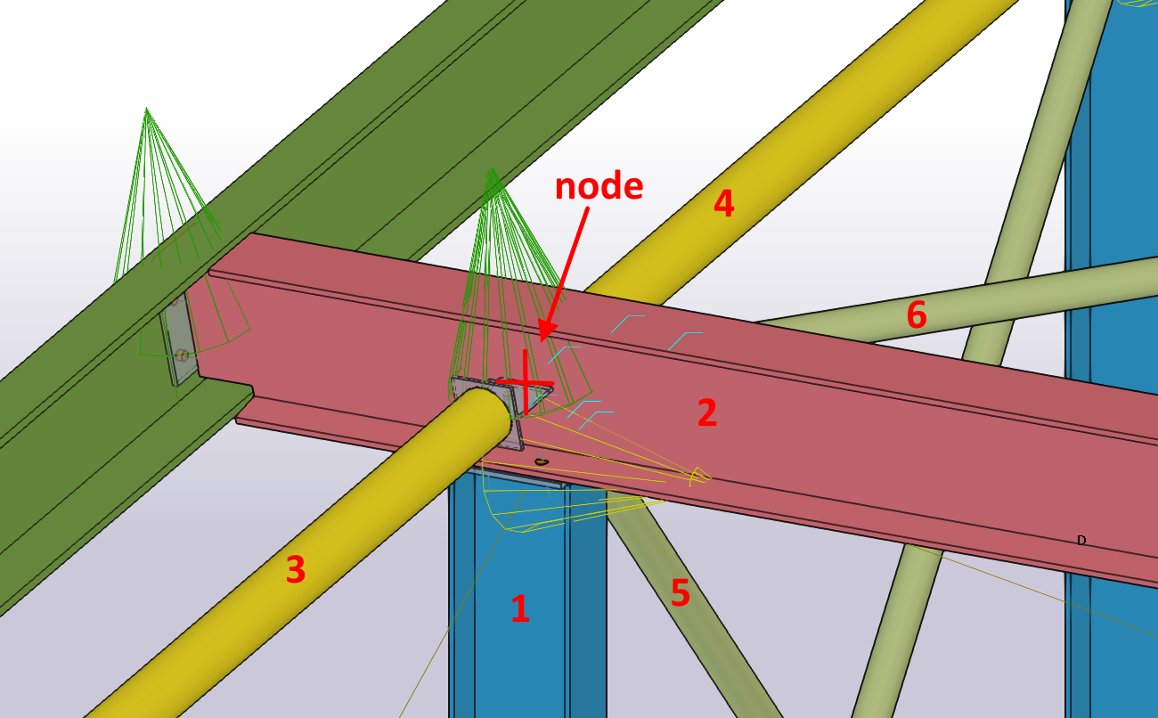
- A continuación, seleccione todos los componentes de la unión (tornillos, soldaduras, placas, etc.) arrastrando el ratón desde la esquina superior derecha hasta la esquina inferior izquierda y confirme con la barra espaciadora.
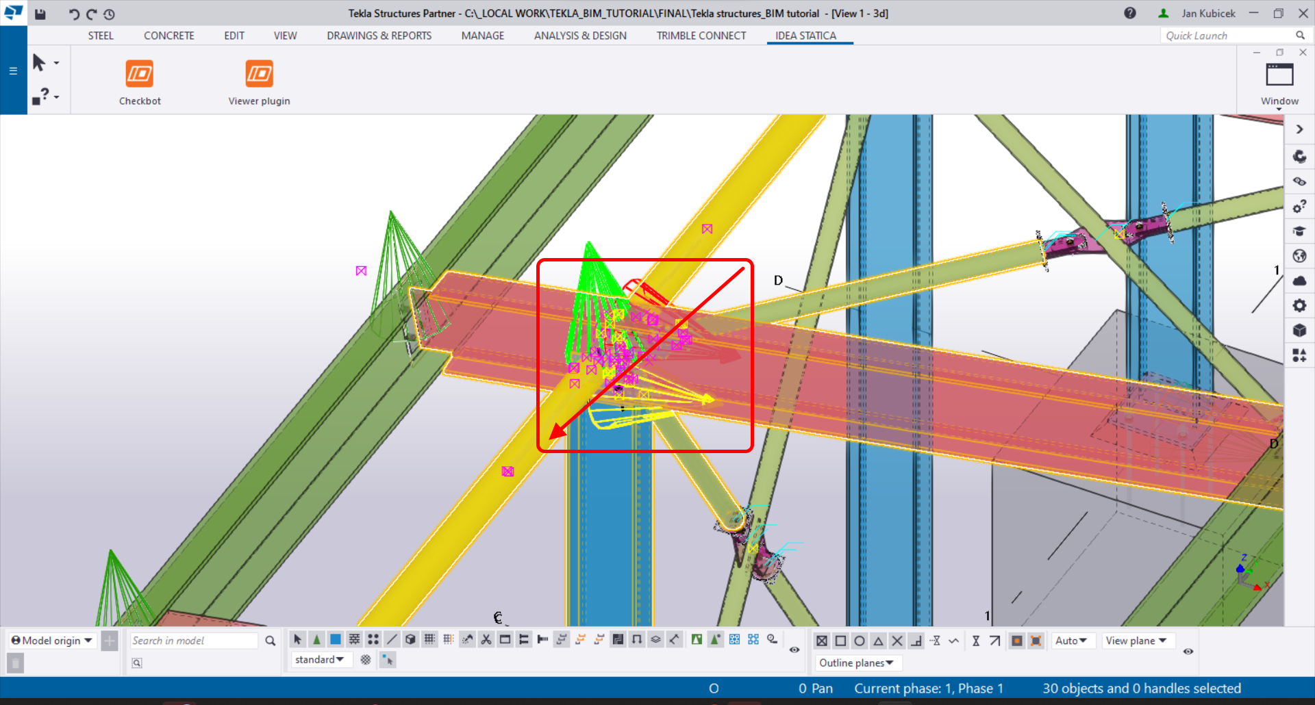
Esto importará todas las partes seleccionadas de la estructura en Checkbot, con las mismas coordenadas, orientaciones y tamaños de sección que en el modelo BIM. El centro de la junta es especificado por usted según la intersección de los elementos.
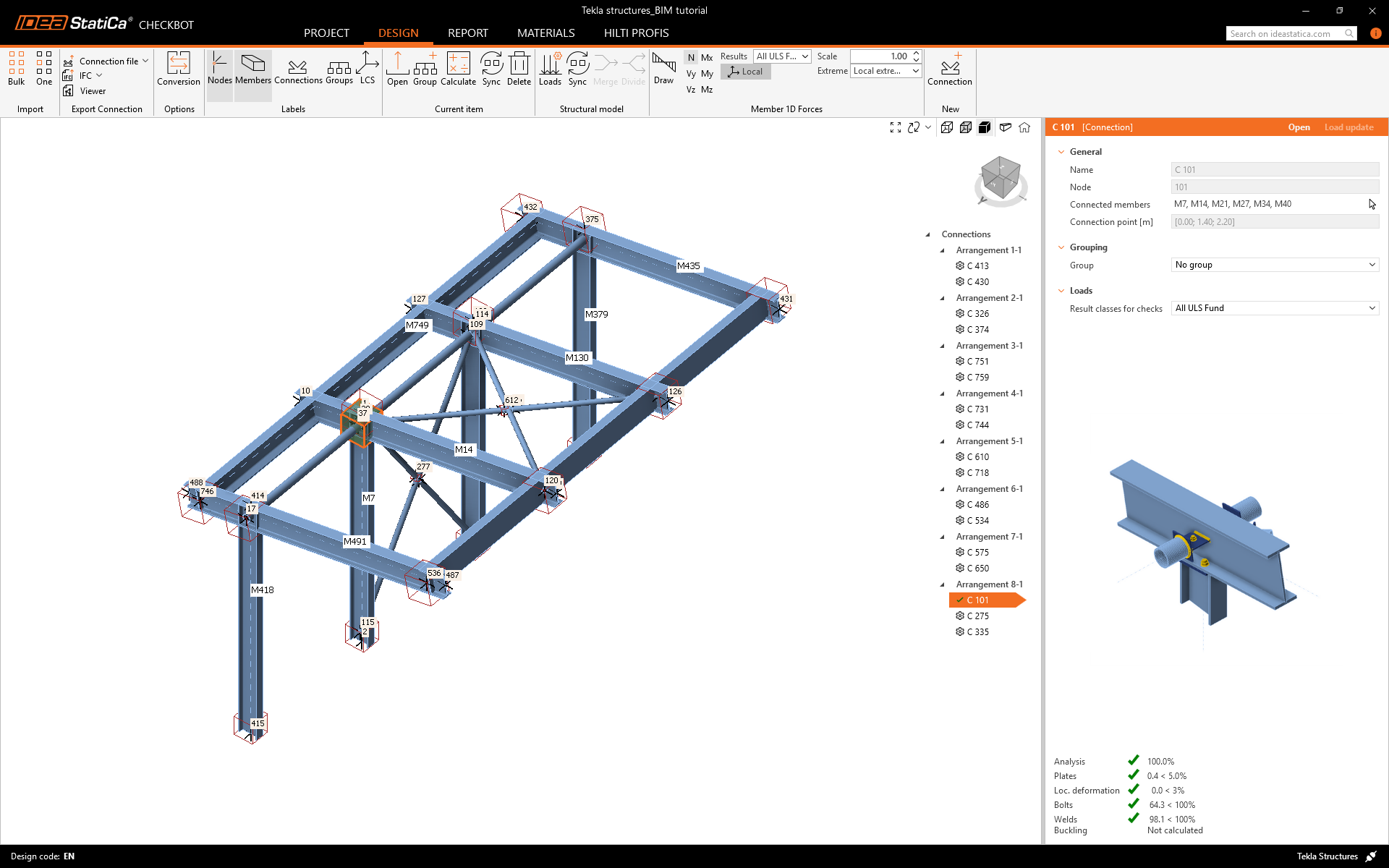
Tenga en cuenta que el espacio de trabajo 3D está diseñado para mostrar una vista general de la estructura importada y no una vista detallada de las uniones reales.
Otra opción es realizar la importación Bulk (masiva). Es más rápida, pero tenga en cuenta que la numeración de nodos y elementos puede ser diferente, lo que afectaría a la correcta importación XLS de los efectos de carga y el equilibrio en la junta.
Seleccione las columnas interiores con arriostramiento, asegurándose de seleccionar también todos los componentes de la unión (tornillos, soldaduras, placas, etc.). Trace el área de selección desde la esquina superior derecha hasta la esquina inferior izquierda.
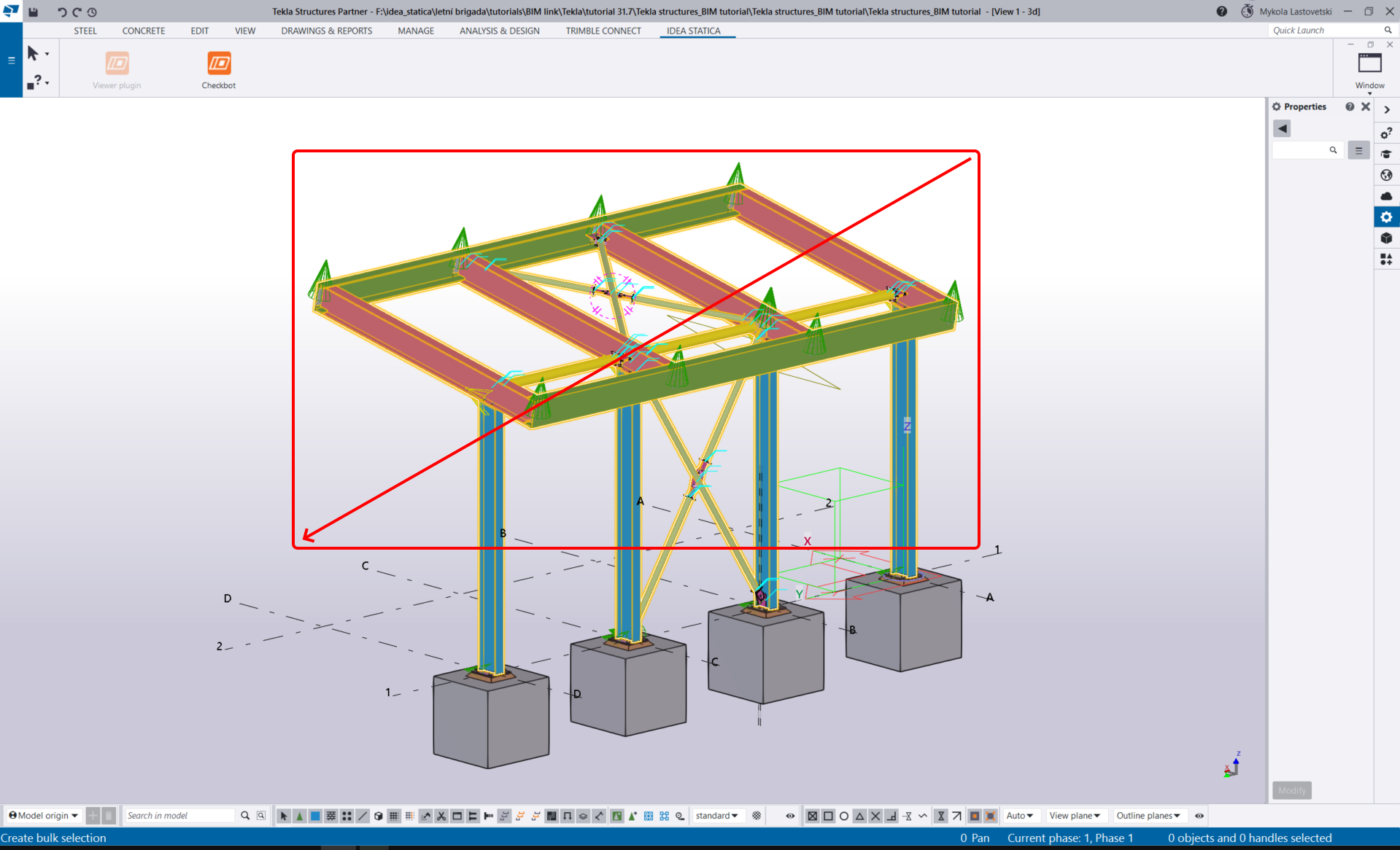
Tras seleccionar todas las partes de la unión, confirme la selección con la barra espaciadora. El centro de la junta es creado automáticamente por el software según la intersección de los elementos.
Para varias soluciones FEA/BIM, también puede importar múltiples uniones en Checkbot. En lugar de seleccionar un nodo y los elementos conectados, puede seleccionar varios nodos y elementos a la vez utilizando los métodos de selección disponibles en la aplicación.
Debido al posible tiempo que puede consumir, recomendamos no importar todas las uniones al mismo tiempo, sino construirlas de forma incremental.
Geometría
La configuración de los elementos se toma de Tekla Structures. Sin embargo, puede cambiar el perfil de la sección y la excentricidad del eje de cualquier elemento en la parte derecha de la pantalla de Checkbot, pero esto romperá el vínculo con la aplicación BIM en esta sesión a menos que se sincronice de nuevo.
En la lista de elementos del proyecto bajo Uniones y con una unión resaltada en Checkbot, puede hacer clic con el botón derecho del ratón y seleccionar Abrir o hacer clic en el comando de la cinta Abrir para comenzar a diseñar, verificar normativamente y generar informes.
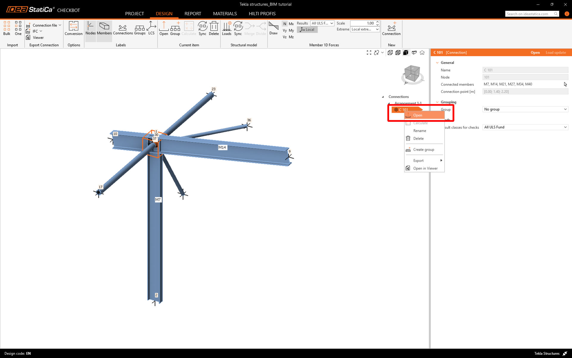
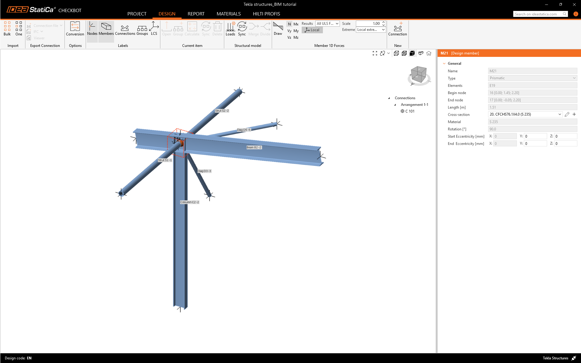
La unión importada se abre en la aplicación IDEA StatiCa Connection.
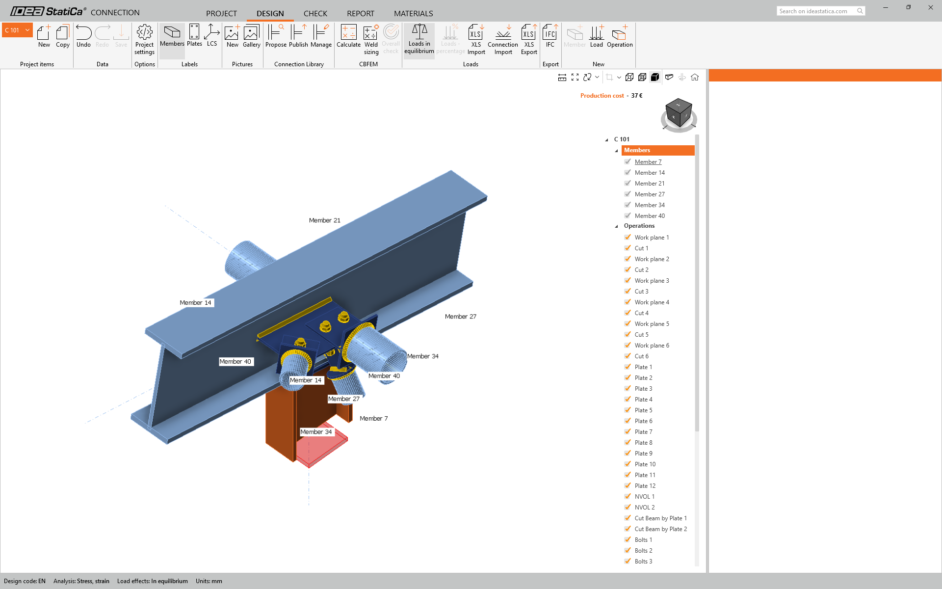
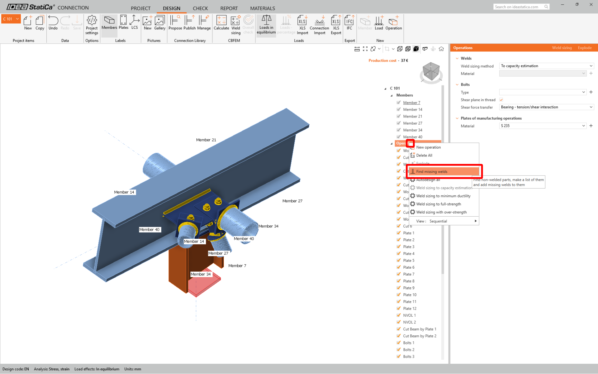
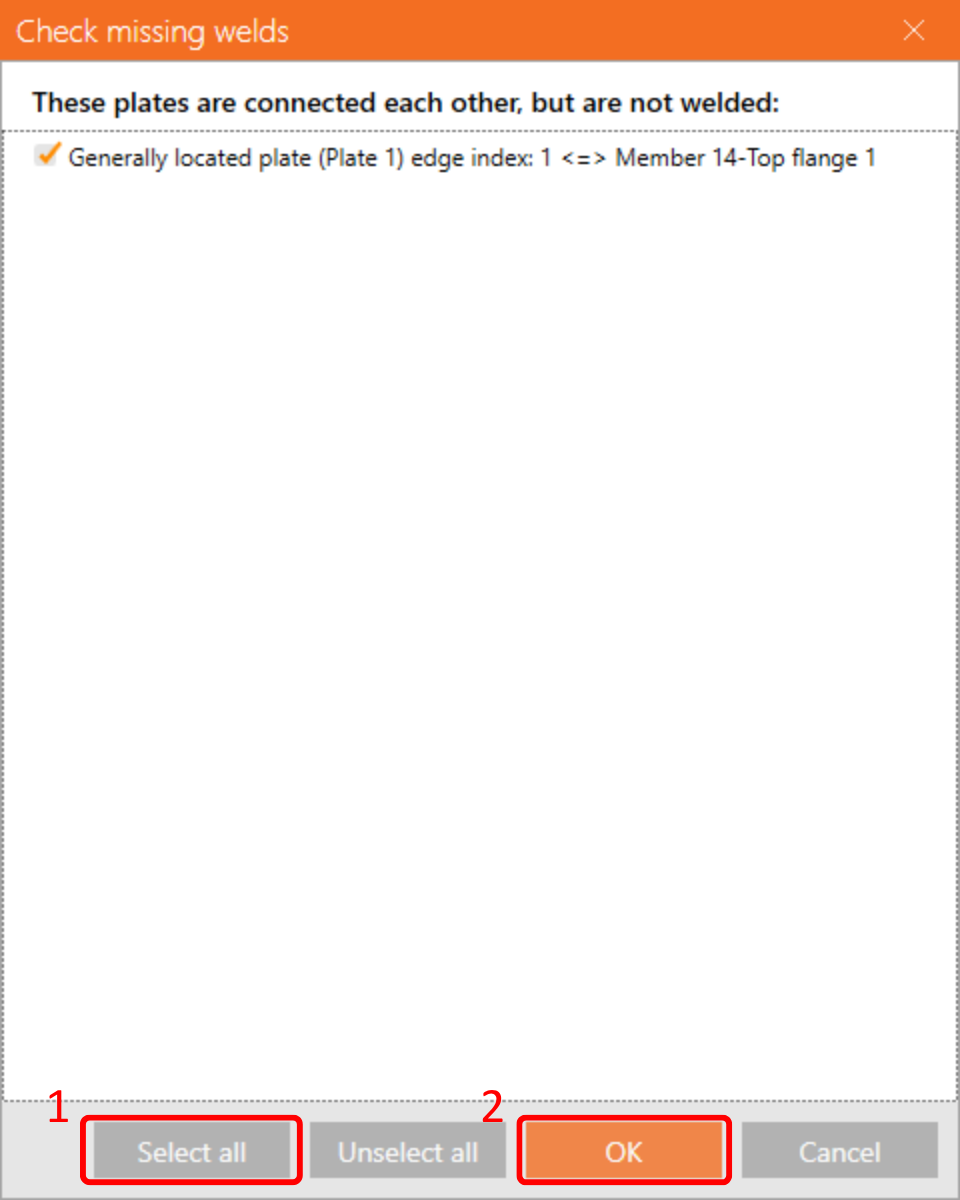
Actualmente, hemos observado que faltan algunas soldaduras en el modelo, pero no se preocupe, ya que esto puede corregirse utilizando la función 'Verificar soldaduras faltantes'.
Marque todas las casillas como se muestra en la siguiente imagen y haga clic en Aceptar.
Efectos de carga
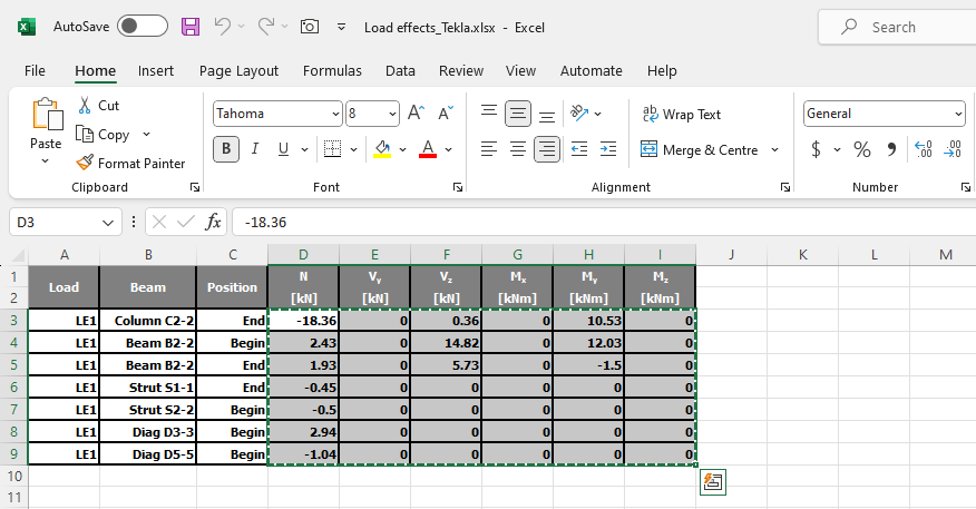
Descargue la hoja de Excel adjunta con los efectos de carga y ábrala. Seleccione los valores de las fuerzas internas en la tabla y cópielos (Ctrl + C).
Luego, en IDEA StatiCa Connection, seleccione el botón XLS Import en la cinta superior.
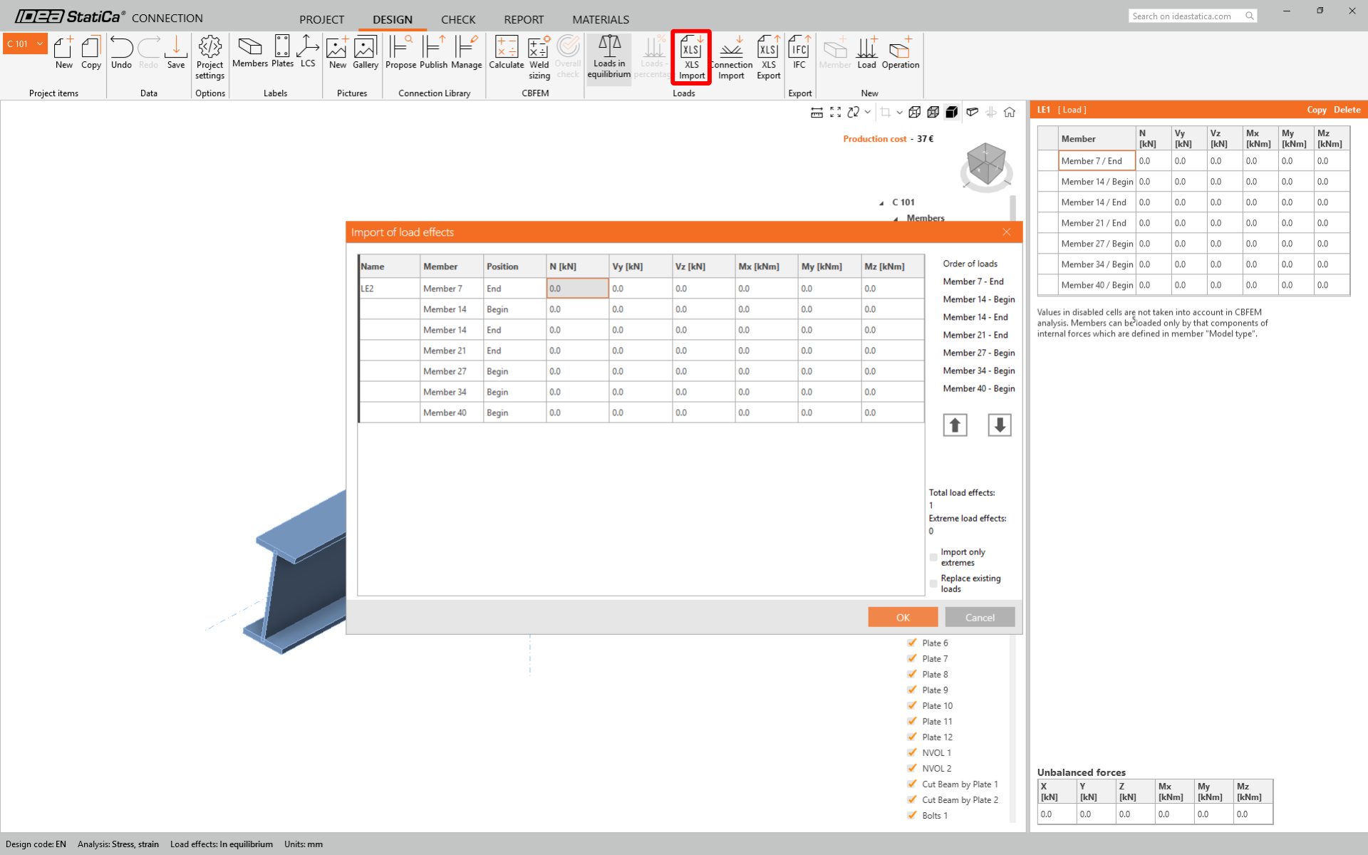
Con un clic derecho, seleccione la primera celda y pegue (Ctrl + V) los valores de las fuerzas internas.
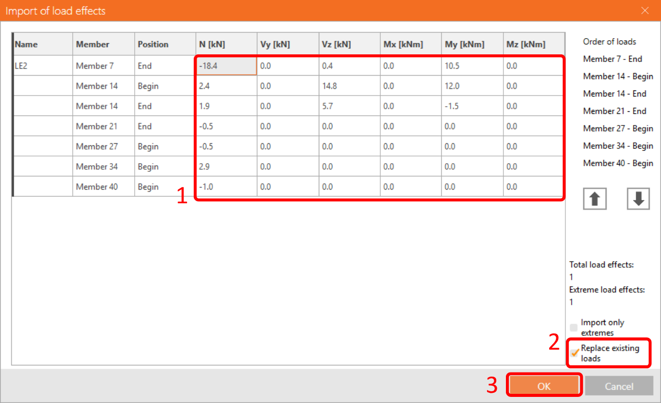
Tenga en cuenta que debe tener el mismo orden de filas y columnas en la tabla de Excel que en la tabla de efectos de carga en la aplicación IDEA StatiCa Connection. Si las filas o columnas están intercambiadas, obtendrá una entrada incorrecta de fuerzas internas en los elementos.
Diseño
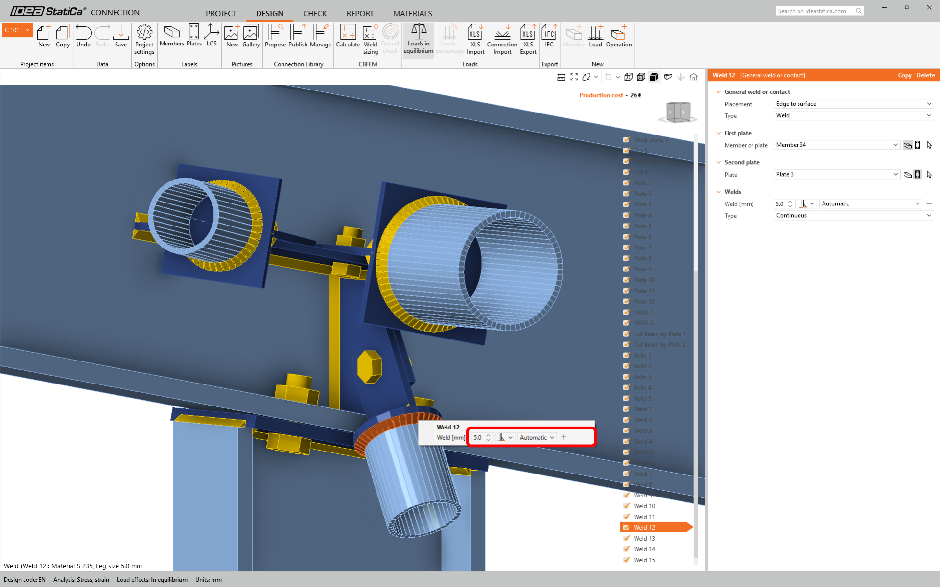
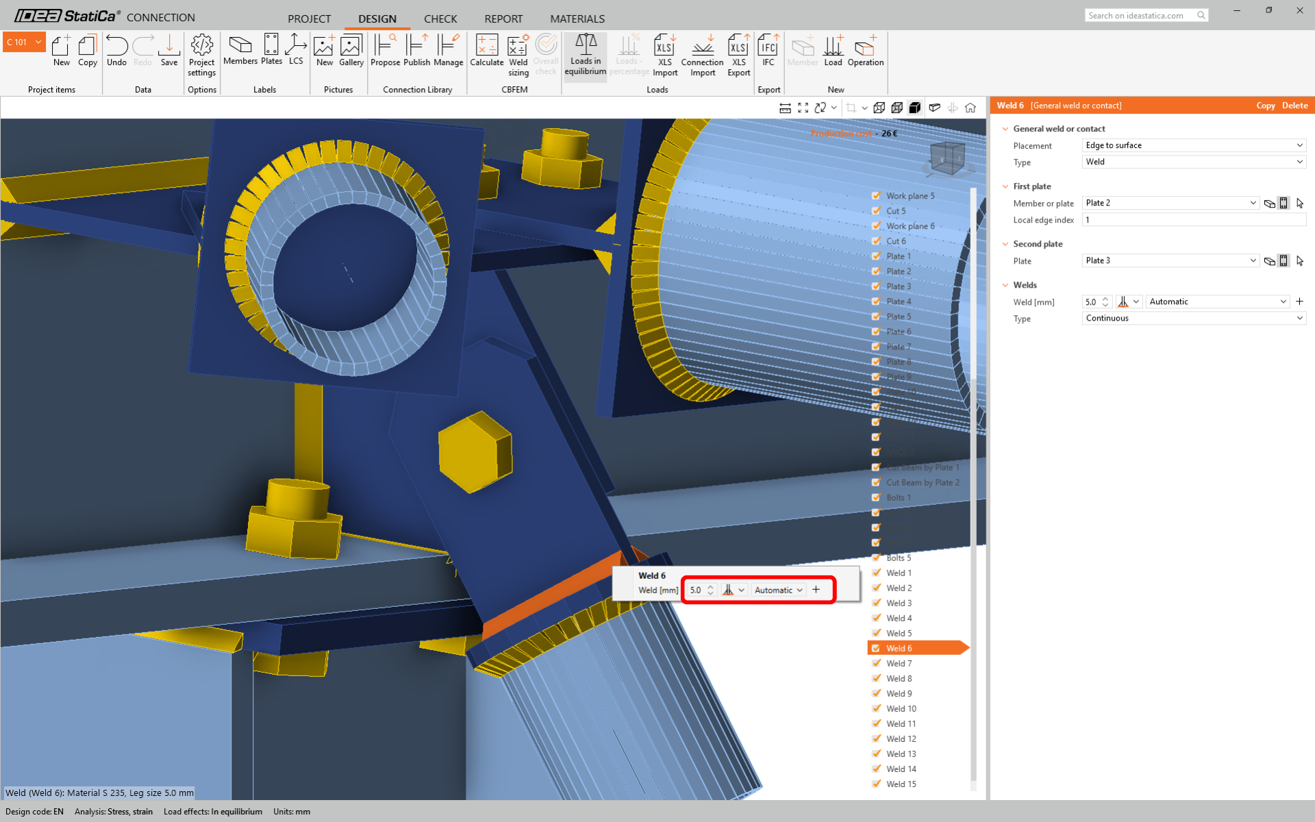
En nuestro modelo de unión importado, podemos ver que algunas soldaduras en los elementos tubulares se importaron incorrectamente y deben corregirse.
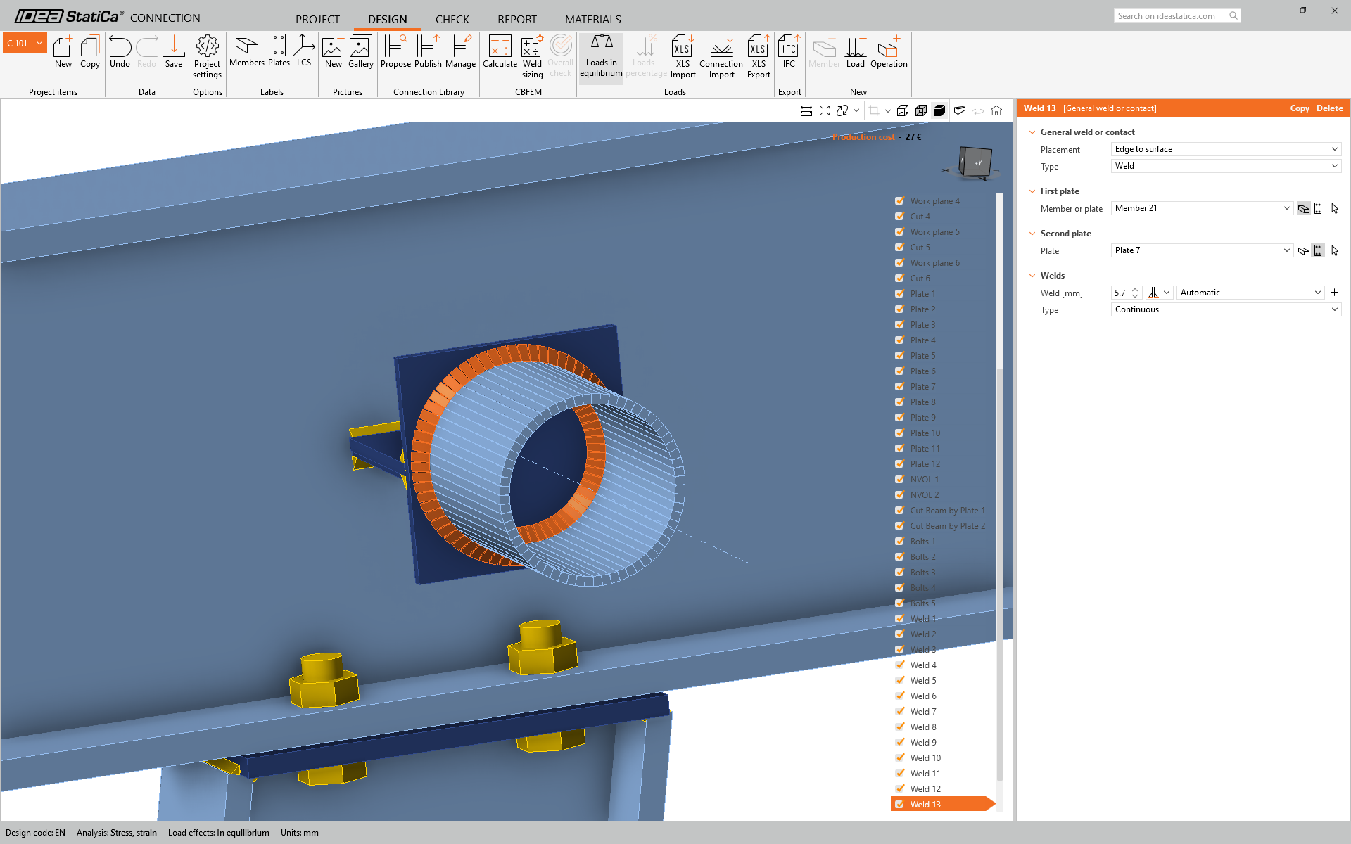
Para el elemento Strut S1-1 cambie el tamaño de la soldadura a 5 mm y la orientación del lado trasero.
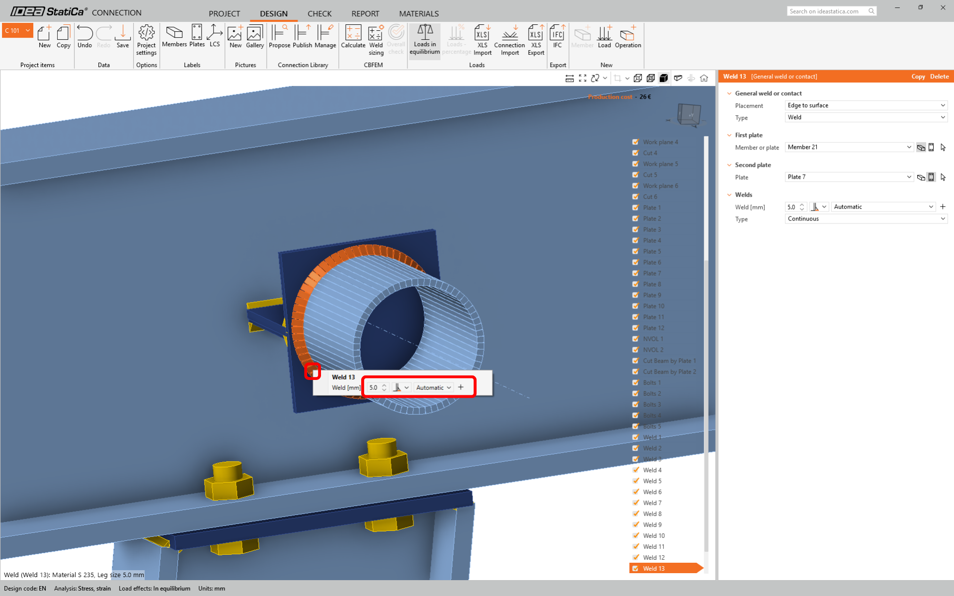
Para el elemento Strut S2-2 cambie el tamaño de la soldadura a 5 mm y la orientación del lado trasero.
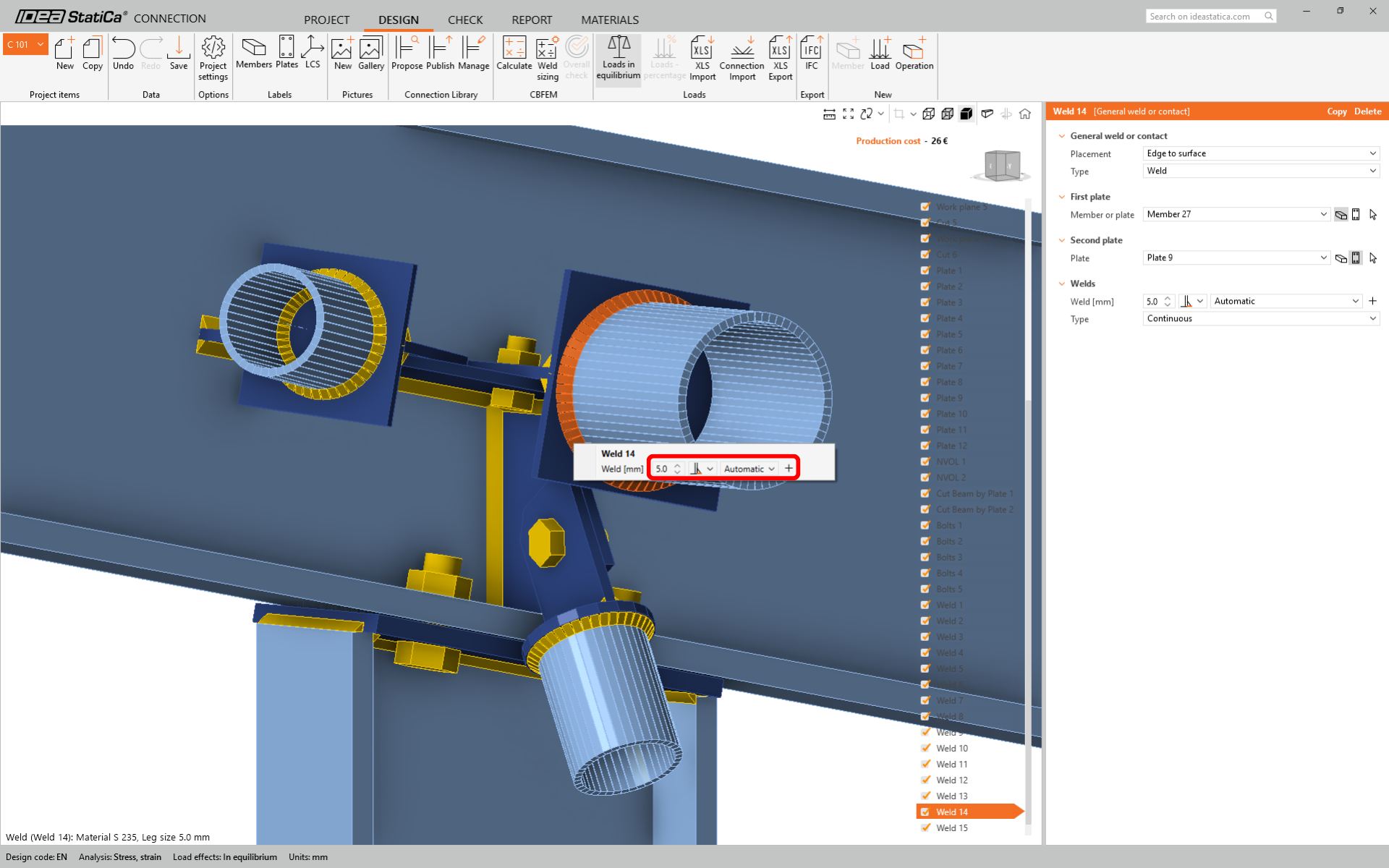
Para el elemento Diag 3-3 cambie el tamaño de la soldadura a 5 mm y la orientación del lado trasero.

Para el elemento Diag 5-5 cambie el tamaño de la soldadura a 5 mm y la orientación del lado trasero.
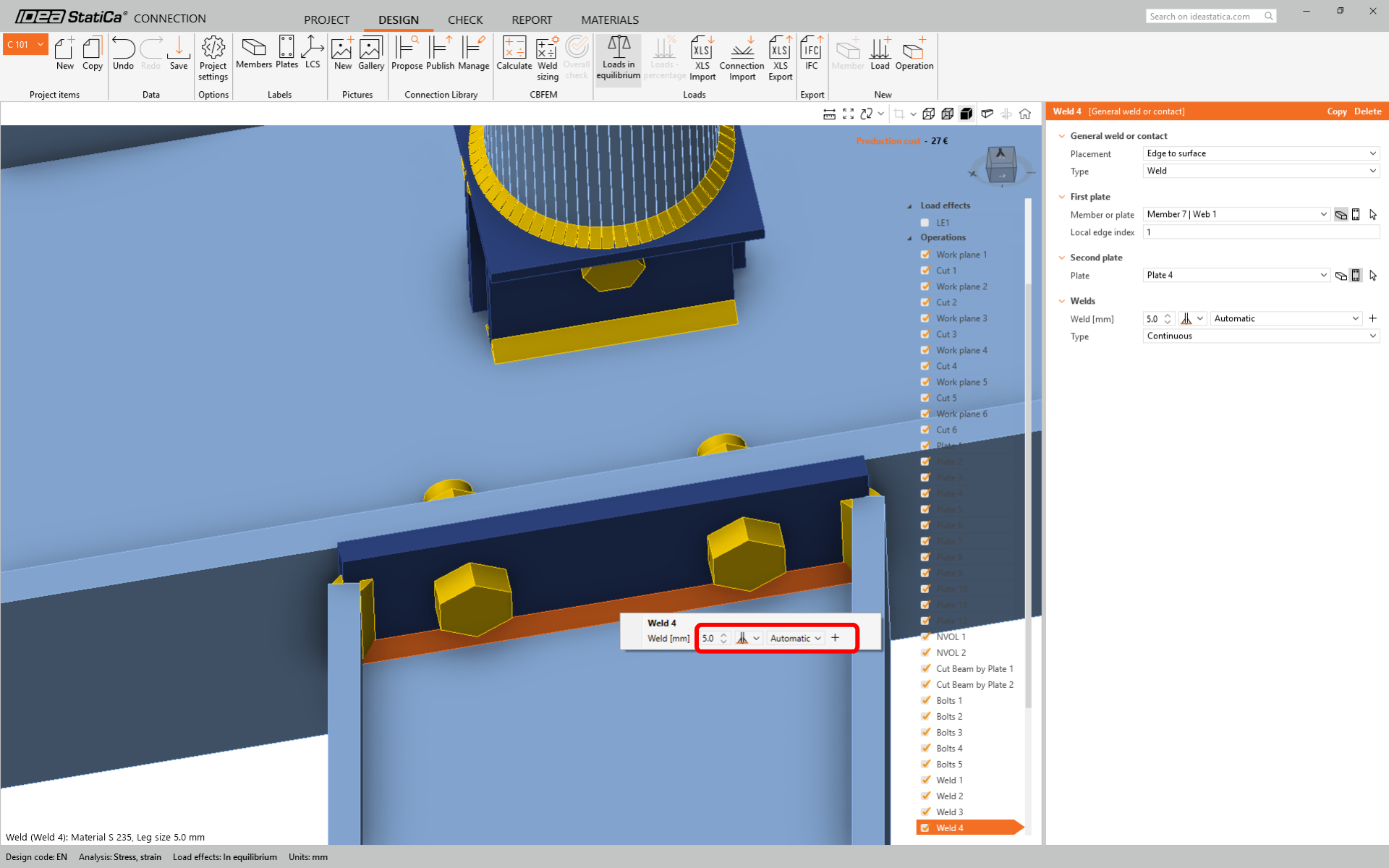
Cambie la orientación de la soldadura entre Tongue y la placa tapa a soldadura de filete doble como se muestra en la siguiente imagen.
Cambie la operación de soldadura entre Plate 3 y Column C2-2 como se muestra en la siguiente imagen.
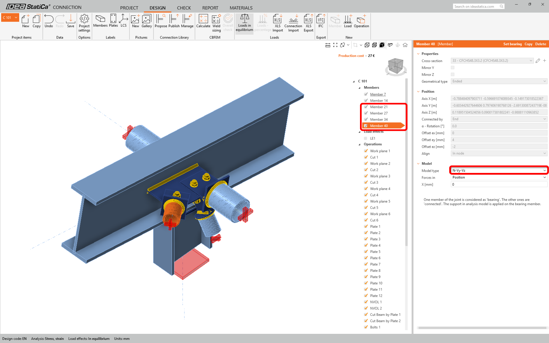
Vamos a utilizar una unión de un solo tornillo para el elemento de arriostramiento de separación y diagonal. Para este tipo de unión, también debemos cambiar el Tipo de modelo del elemento de arriostramiento a N-Vy-Vz. Seleccione los elementos en la lista de Elementos: Strut S1-1, Strut S1-2, Diag D3-3, Diag D5-5, y modifique el Tipo de modelo en la lista desplegable.
Verificación normativa e Informe
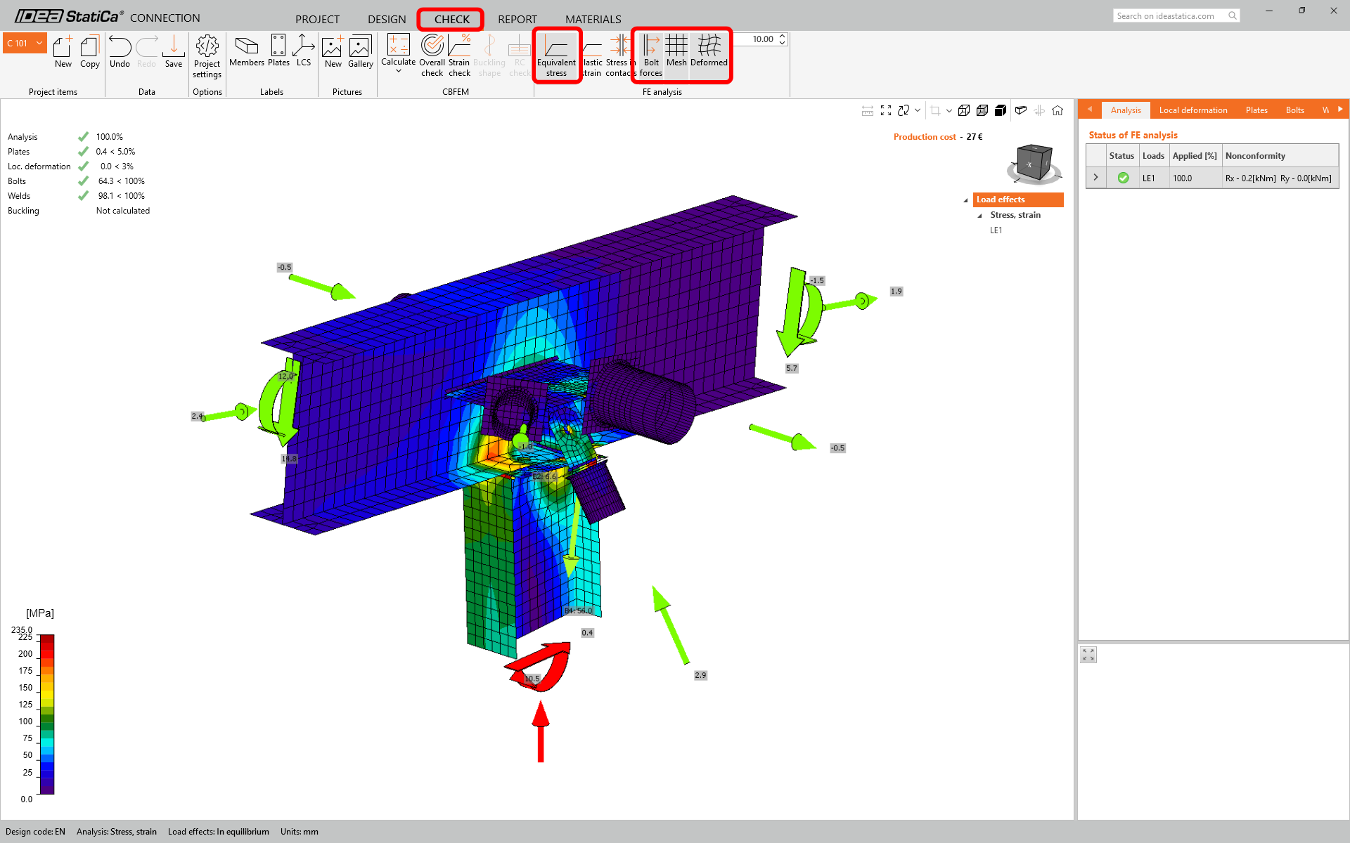
Ahora ejecute una verificación normativa usando el icono Calcular en el panel CBFEM de la cinta superior.
En IDEA StatiCa Connection puede realizar muchos tipos diferentes de análisis y verificaciones normativas. Para más información, consulte aquí.
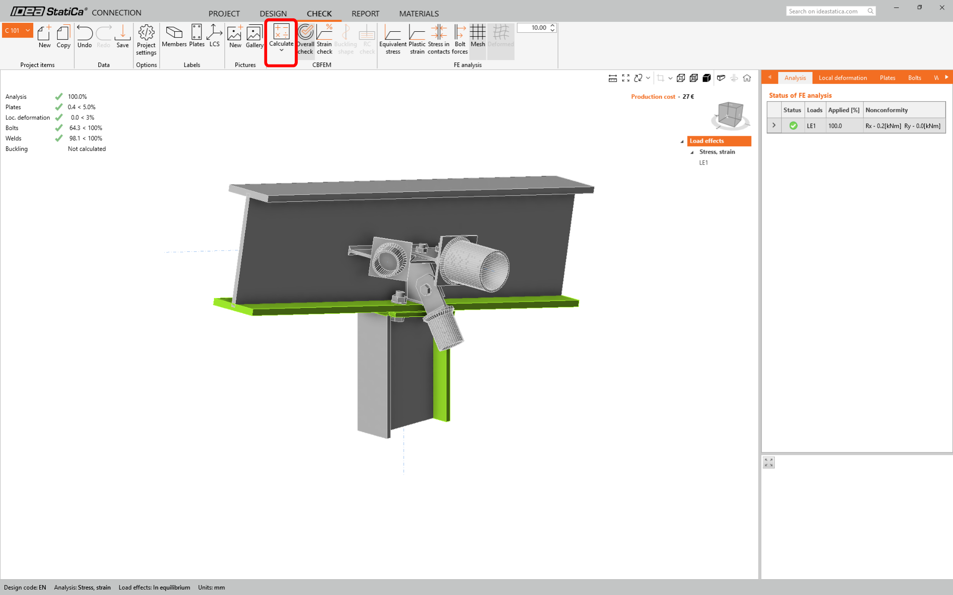
Vaya a la pestaña de visualización Verificación, y active Tensión equivalente, Fuerzas en tornillos, Malla y Deformada desde la cinta para obtener una imagen completa de lo que ocurre en la junta.
Una vez finalizada la verificación normativa, en la pestaña Informe puede crear el informe con los resultados y diagramas de su modelo de unión.
El informe puede imprimirse o guardarse en varios formatos. Para más información, consulte aquí.

Guarde y salga de esta unión de vuelta a Checkbot.
En Checkbot, verá que hay una marca verde junto a la unión. Esto significa que la unión es válida y ha superado todas las verificaciones normativas. En el panel de Unión, también puede ver una representación de la unión y un resumen de los resultados de la verificación normativa.
Si hay varias uniones presentes en Checkbot, cada una debe abrirse, diseñarse y verificarse normativamente.
Puede continuar con el diseño de uniones adicionales utilizando el mismo enfoque presentado anteriormente.
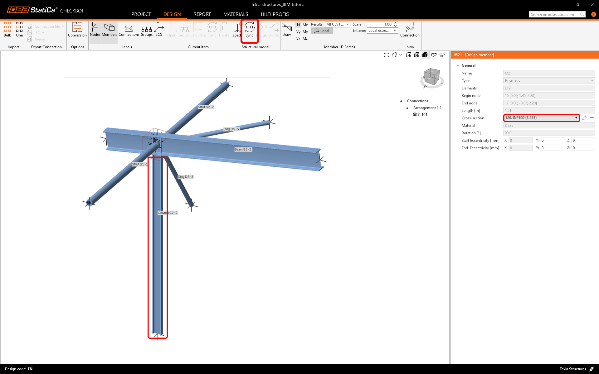
Sincronizar modelo
A veces, hay cambios en su modelo FEA/BIM, como diferentes tamaños de sección de elementos o cargas. Estos pueden sincronizarse entre Checkbot y el modelo FEA/BIM.
Hay dos alternativas posibles:
- Sincronizar el elemento actual (si hay una o más juntas seleccionadas)
- Sincronizar todo el modelo estructural importado

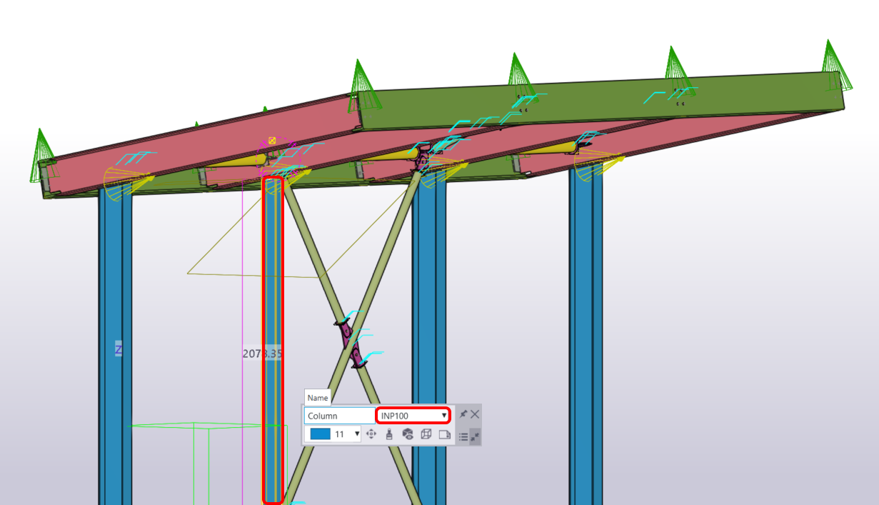
Para probar esta función, puede cambiar el tamaño o la forma de la sección de un elemento en su aplicación BIM o modificar un caso de carga o combinación, etc.: cambie la columna seleccionada a una sección más pequeña.
En Checkbot seleccione las uniones diseñadas (puede haber más de una) y en el panel del elemento actual seleccione Sincronizar.
El proyecto de Checkbot se actualizará, el diseño de la unión se conserva pero los resultados quedarán invalidados. Puede ver que la columna ahora está actualizada, coincidiendo con el cambio en el modelo BIM.
Simplemente realice la verificación normativa de las uniones resaltadas de nuevo seleccionando Calcular en el panel del elemento actual. Recuerde que cambios mayores en el modelo pueden requerir pasos de validación adicionales con las uniones afectadas (como se indica arriba).

Si las uniones no dan los resultados deseados, puede abrirlas de nuevo para optimizar el diseño (es decir, reforzarlas si no superan la verificación normativa o aligerar si la utilización es demasiado baja).
Ha vinculado correctamente Tekla Structures con IDEA StatiCa Connection a través de Checkbot.
Para más información sobre Checkbot, eche un vistazo aquí.
Lea más sobre las limitaciones conocidas del enlace BIM de Tekla Structures.