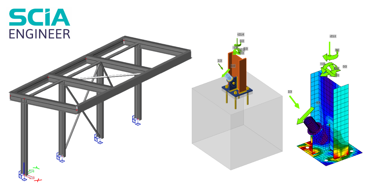
SCIA Engineer BIM link para el diseño de uniones de acero (EN)
Cómo activar el enlace
- Descargue e instale la última versión de IDEA StatiCa
- Asegúrese de que está utilizando una versión compatible de su solución FEA
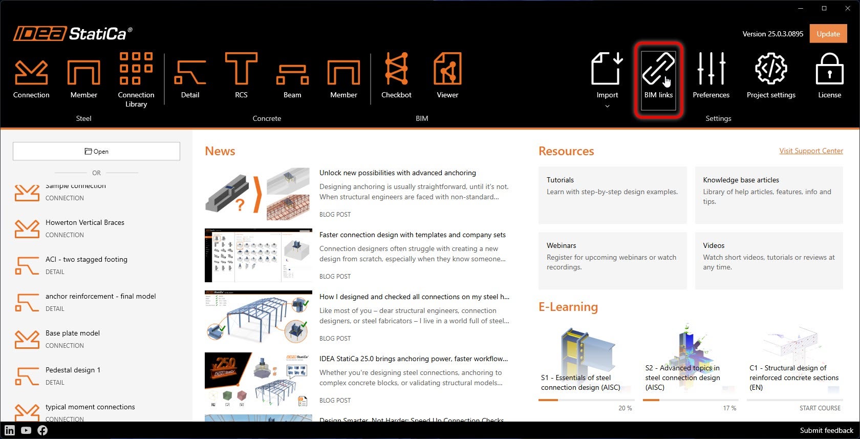
IDEA StatiCa integra enlaces BIM en su software FEA durante su instalación. Puede comprobar el estado e integrar más enlaces BIM ejecutando IDEA StatiCa y abriendo los enlaces BIM. Tenga en cuenta que algunos programas FEA requieren pasos adicionales para activar completamente su enlace BIM con IDEA StatiCa.
Puede aparecer una notificación "¿Desea permitir que esta aplicación realice cambios en su dispositivo?"; si es así, confirme con el botón Sí.
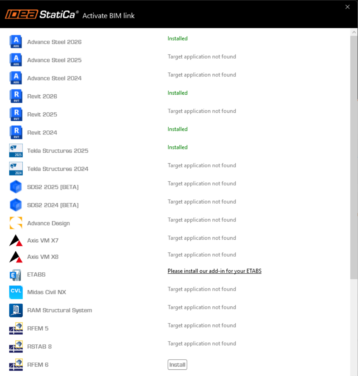
Al hacer clic en Instalar, el enlace BIM para el software seleccionado queda integrado. La pantalla también muestra el estado de los demás enlaces BIM.
Cómo utilizar el enlace
Descargue el proyecto adjunto, ábralo en SCIA Engineer y ejecute el análisis lineal para obtener los esfuerzos internos en la estructura.
El enlace BIM está integrado automáticamente. Puede encontrarlo en la cinta superior en Design -> External tools -> IDEA StatiCa.
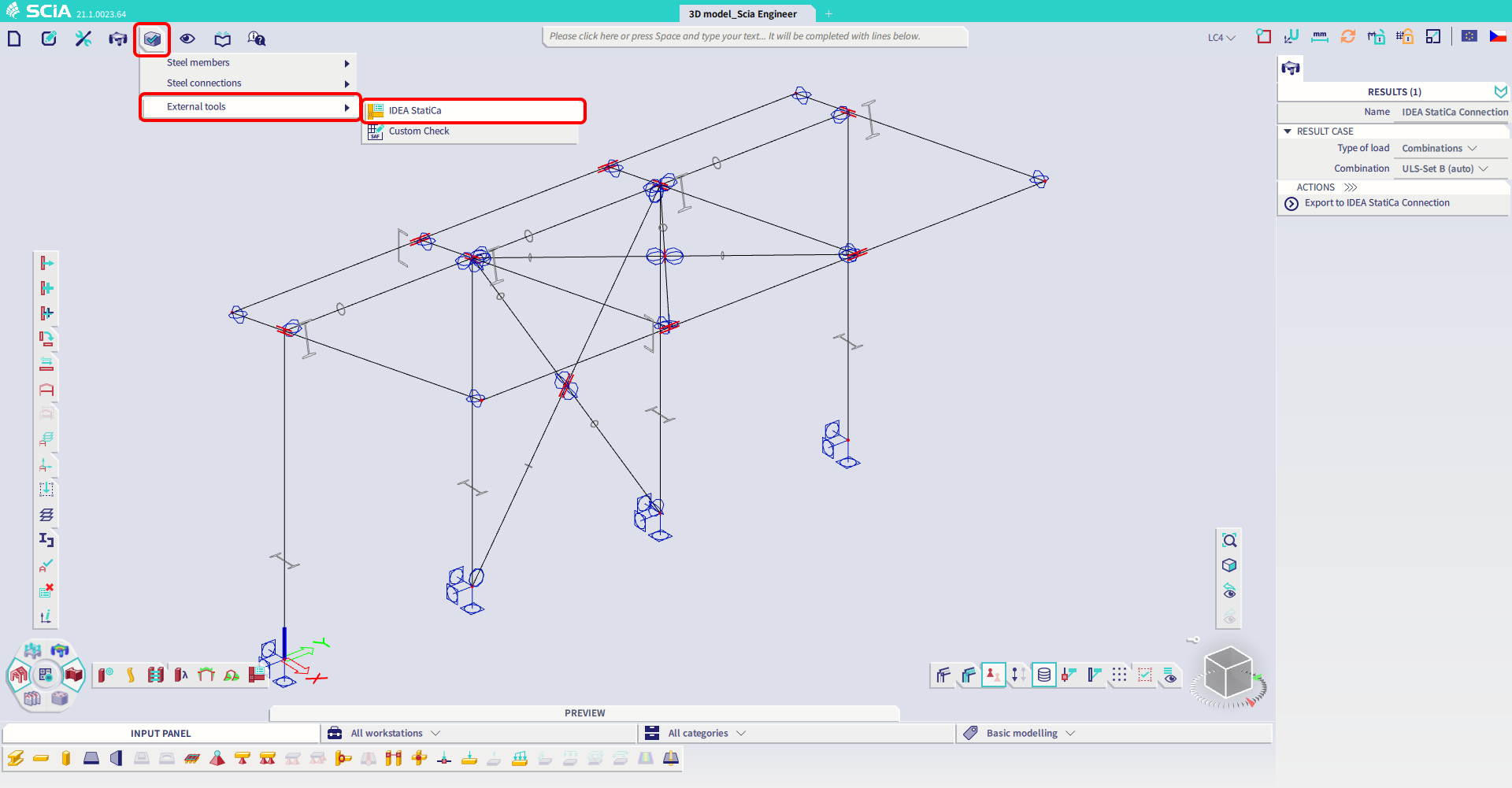
O ejecute el comando "IDEA StatiCa" en la línea de comandos superior.
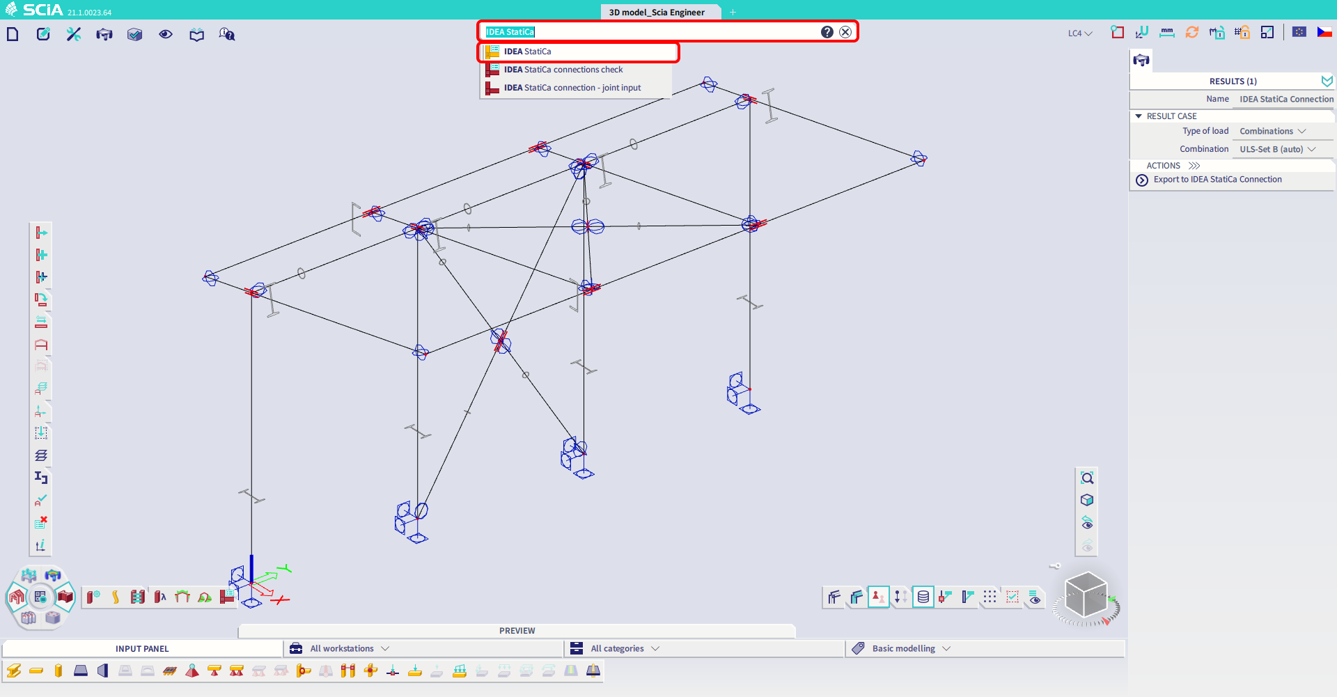
Ambas opciones abrirán la aplicación Checkbot .
Seleccione la opción Nuevo con tipo de proyecto Acero y código de diseño EN. Luego seleccione Crear proyecto.
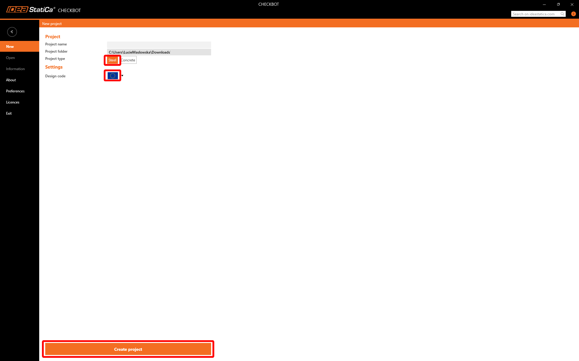
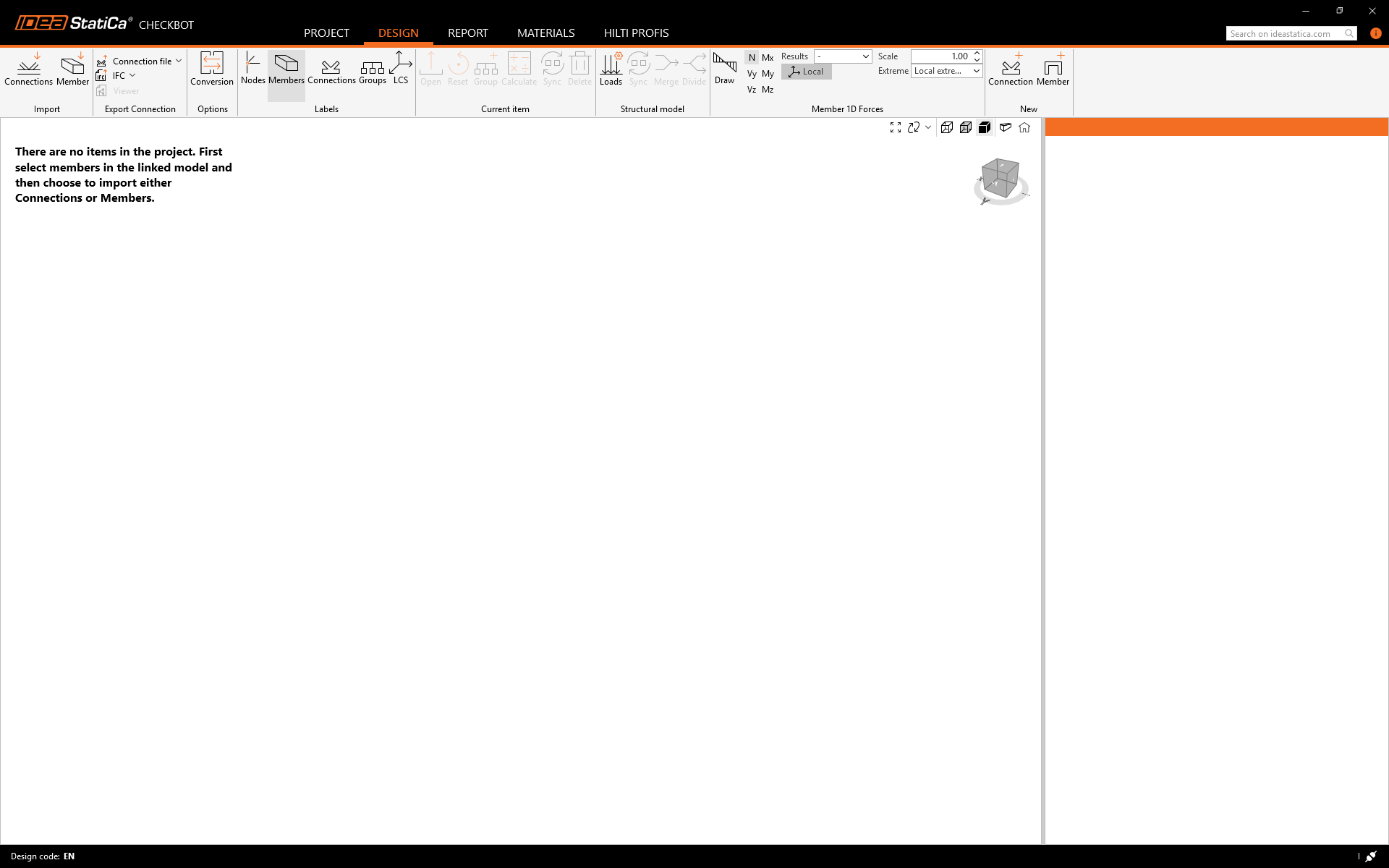
El nuevo proyecto de Checkbot está listo para importar uniones desde SCIA Engineer.
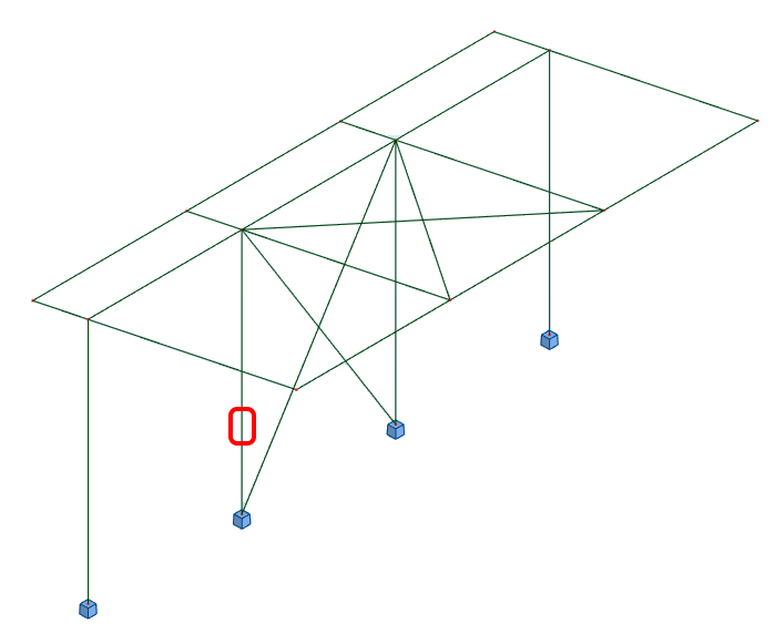
En SCIA Engineer, seleccione una de las columnas interiores con arriostramiento asegurándose de seleccionar también el nodo inferior.

Importar
Luego en Checkbot seleccione Connections.
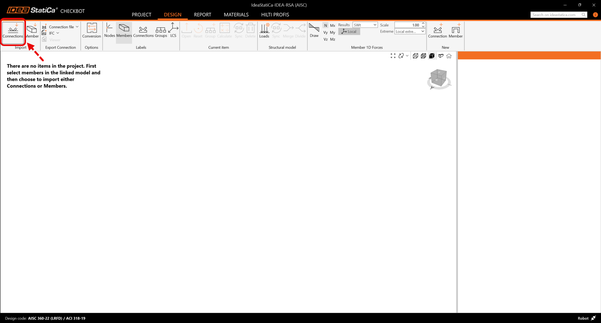
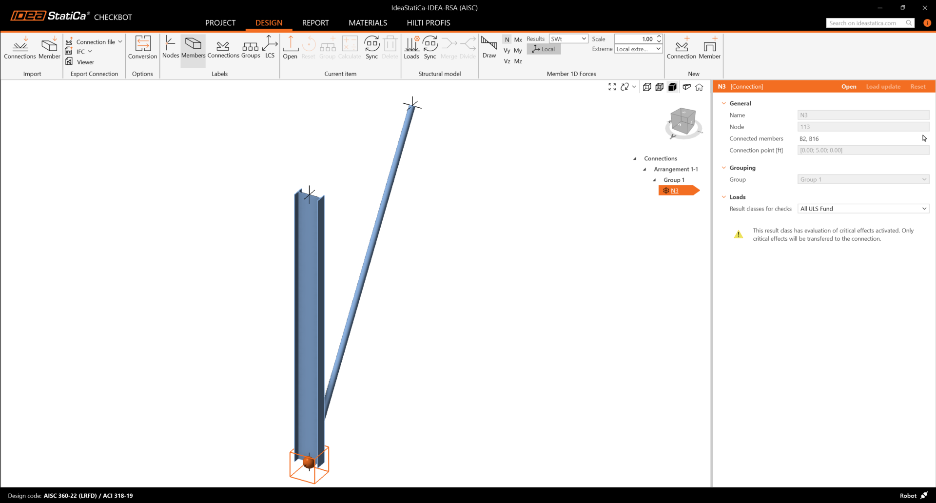
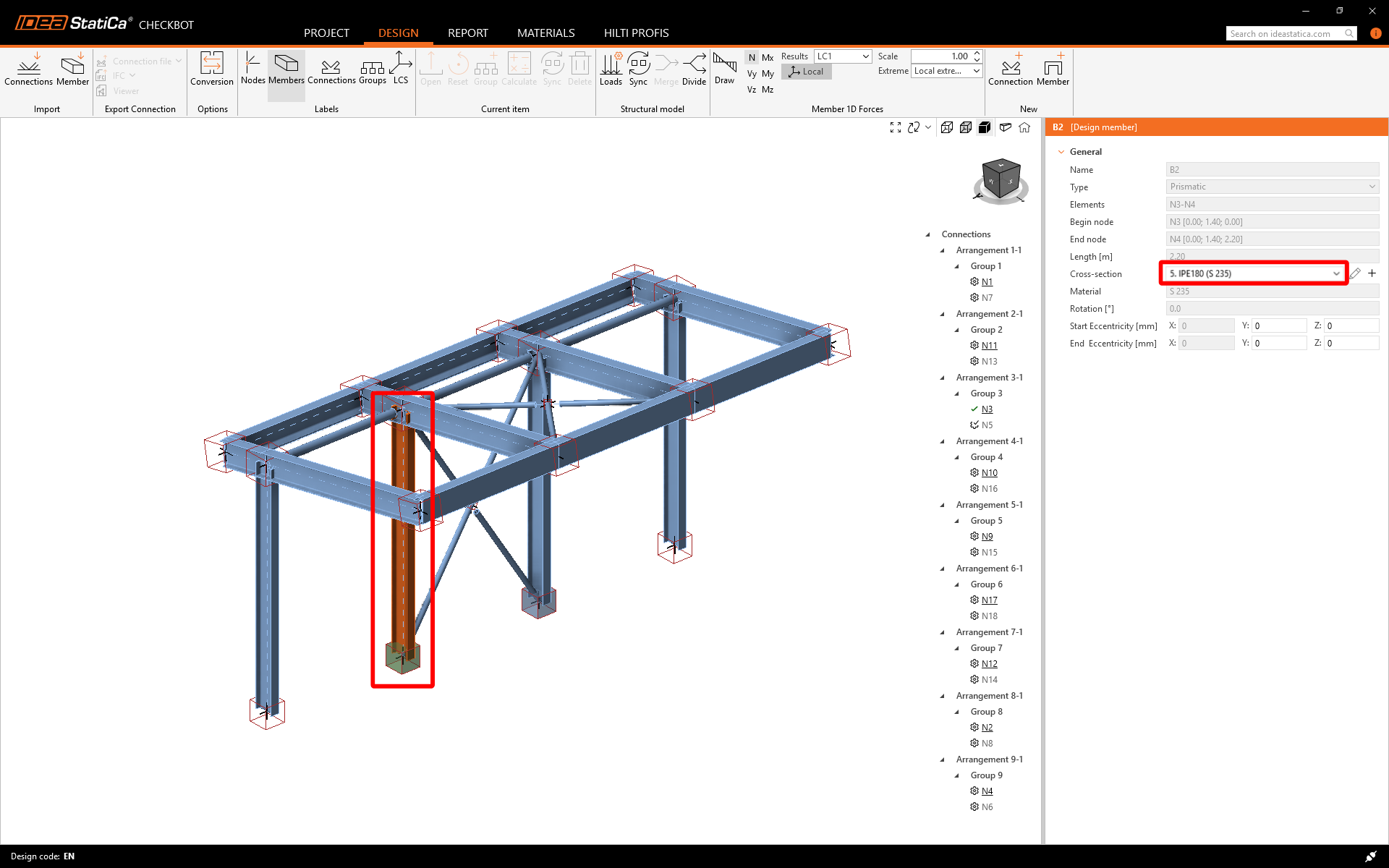
Esto importará el pilar y sus efectos de carga en Checkbot, con las mismas coordenadas, orientaciones y tamaños de sección que en el modelo de análisis por elementos finitos.
Tenga en cuenta que la numeración de nodos y elementos puede ser diferente.
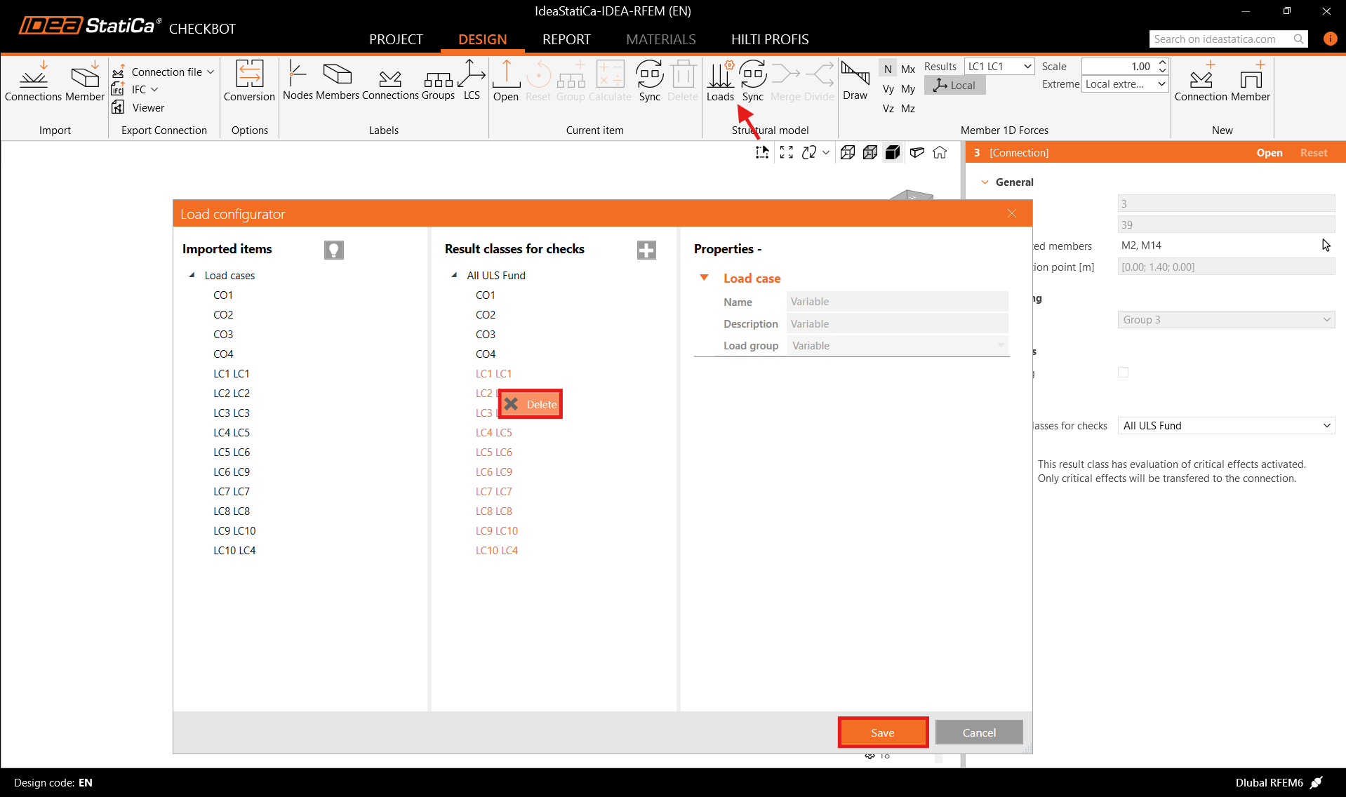
Antes de ejecutar el análisis, asegúrese de revisar las clases de resultado para las verificaciones y ajuste las combinaciones de carga en consecuencia. En el diálogo Configurador de cargas, puede ver todos los casos de carga e hipótesis importados a la izquierda y las clases de resultado utilizadas para las verificaciones en el centro. Si algunos casos de carga no son relevantes para su verificación de diseño, exclúyalos haciendo clic derecho sobre las cargas seleccionadas y eliminándolas de la lista de clases de resultado.
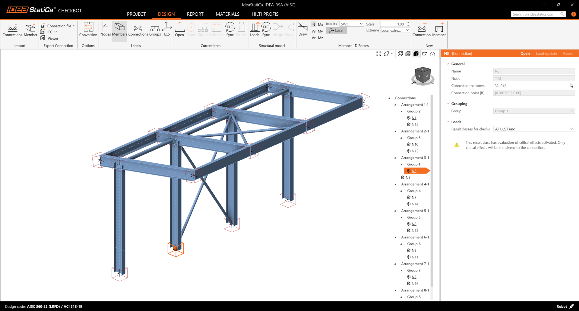
Tenga en cuenta que el espacio de trabajo 3D está diseñado para mostrar una vista general de la estructura importada y no una vista detallada de las uniones reales. Para más información sobre Checkbot, consulte aquí.
Para varias soluciones de análisis por elementos finitos, también puede importar múltiples uniones en Checkbot de la misma manera que se describe anteriormente. En lugar de seleccionar un nodo y los elementos conectados, puede seleccionar múltiples nodos y elementos e importarlos todos a la vez.
Geometría
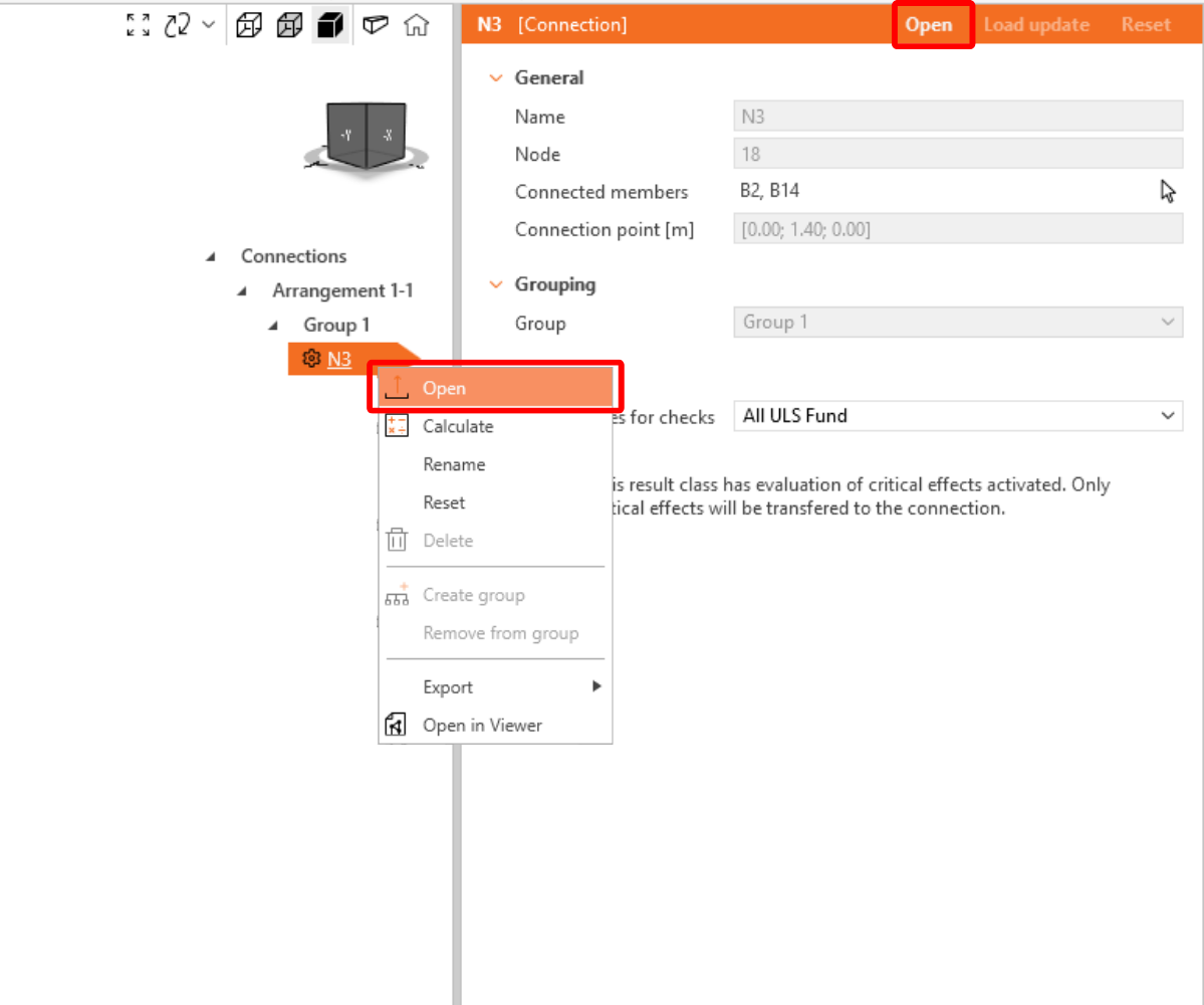
En la lista de elementos del proyecto bajo Conexiones y con una unión resaltada en Checkbot, puede hacer clic con el botón derecho del ratón y seleccionar Abrir o hacer clic en el comando de la cinta Abrir para comenzar a diseñar, realizar la verificación normativa e informes.
La configuración de los elementos se toma de la aplicación FEA original. Sin embargo, puede cambiar el tamaño de la sección de cualquier elemento en la pantalla principal de Checkbot, pero esto romperá el vínculo con la aplicación FEA en esta sesión a menos que se sincronice de nuevo.
La unión importada se abre en la aplicación IDEA StatiCa Connection.
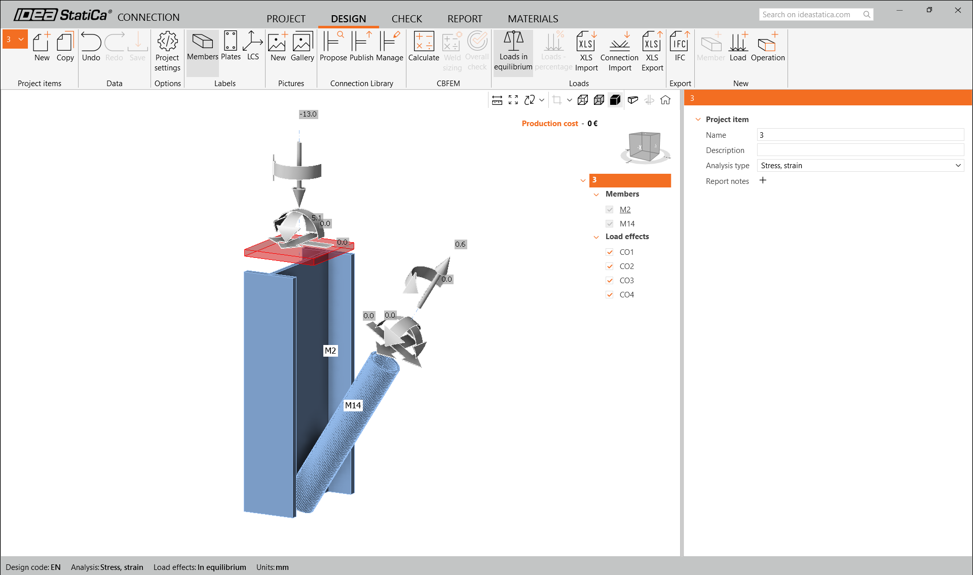
Es posible que no vea ningún efecto de carga o que vea efectos de carga diferentes a los de su solución FEA, dependiendo de cómo se hayan definido las combinaciones de casos de carga. Por defecto, IDEA StatiCa elegirá el más crítico para la verificación normativa. (* Algunas soluciones BIM no pueden almacenar los resultados de las combinaciones de casos de carga)
Para más información sobre los efectos de carga, consulte aquí.
Diseño
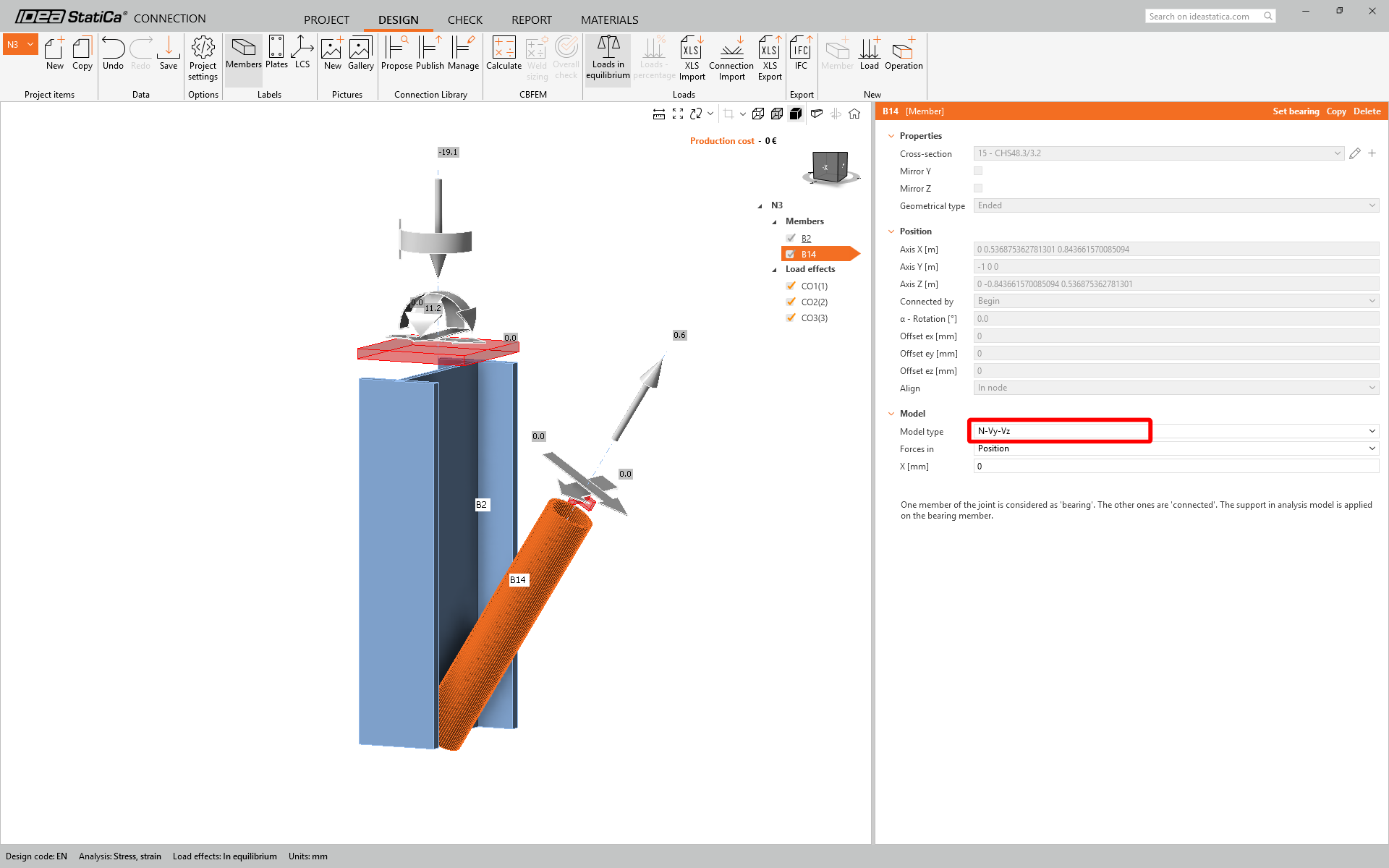
Vamos a utilizar una unión de un solo tornillo para la diagonal de arriostramiento. Para este tipo de unión, también debemos cambiar el Tipo de modelo del elemento diagonal a N-Vy-Vz. Seleccione la diagonal en la lista de Elementos y modifique el Tipo de modelo en la lista desplegable.
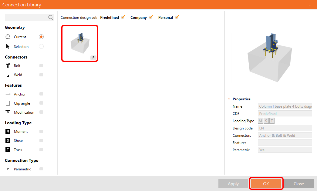
Vamos a utilizar la Connection Library para generar una unión. Seleccione Proponer e IDEA StatiCa presentará posibles soluciones para la geometría actual.

Connection Library le muestra las posibles soluciones para la geometría actual. Elija la plantilla Column I base plate 4 bolts diagonal bolted weak y pulse OK.
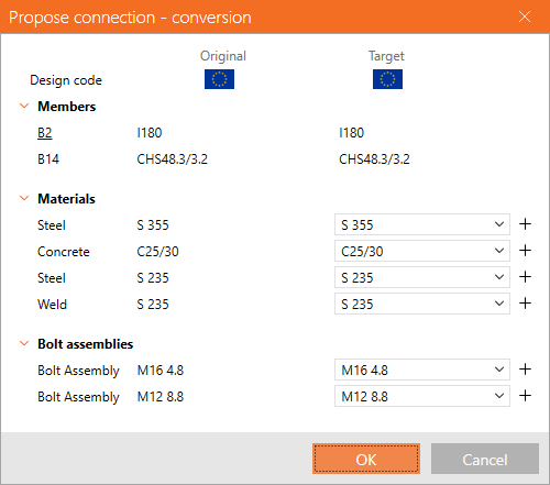
Acepte los valores propuestos en la pestaña de conversión y pulse OK.
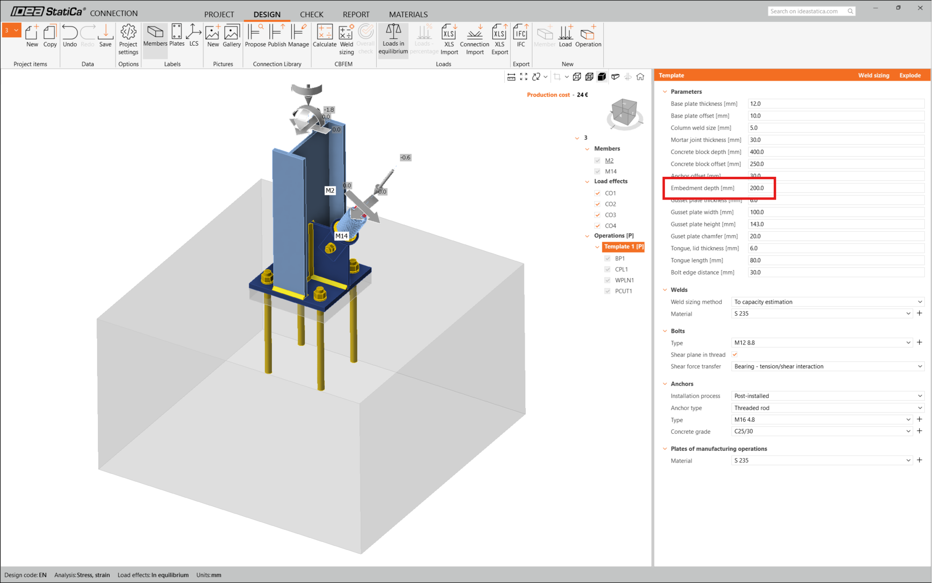
Edite los parámetros de esta plantilla para ajustarlos al diseño deseado: Espesor de la placa base a 12 mm, Desplazamiento de la placa base a 10 mm, Desplazamiento del bloque de hormigón a 250 mm, Espesor de la placa de unión a 6 mm y Ancho de la placa de unión a 100 mm.
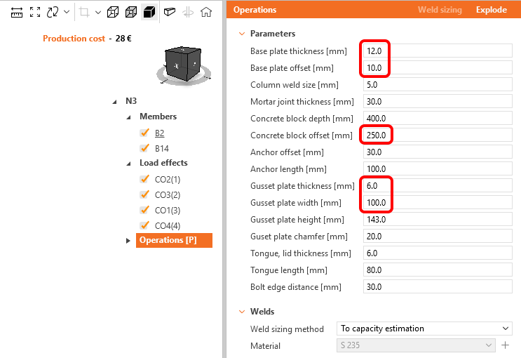
Este es el aspecto inicial de la unión.
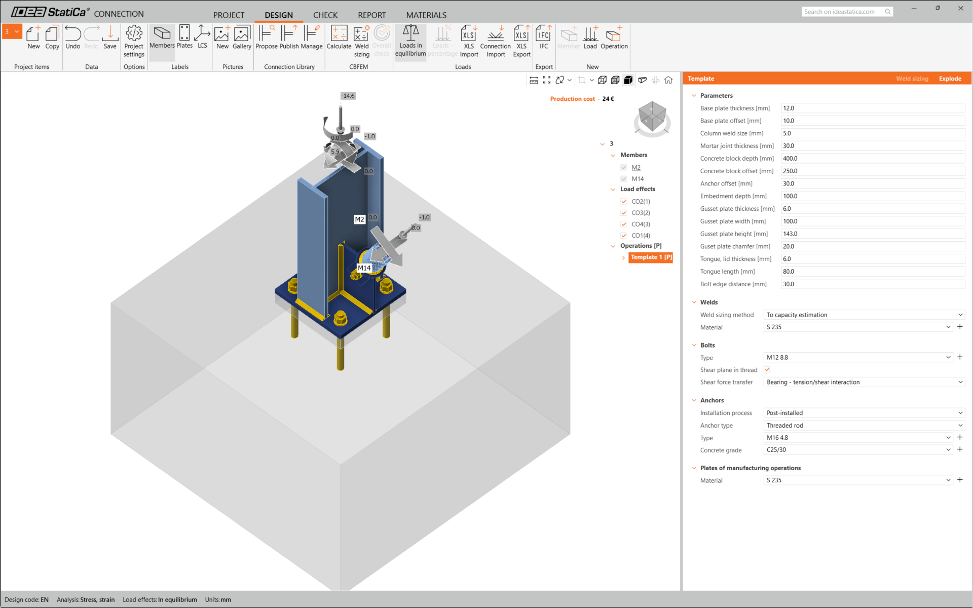
Con esto se completa el diseño de la unión para la placa base de la columna con una diagonal de arriostramiento.
Verificación normativa e Informe
Ahora ejecute una verificación normativa utilizando el icono Calcular en el panel CBFEM de la cinta superior.
Dentro de IDEA StatiCa Connection, puede realizar muchos tipos diferentes de análisis y verificaciones normativas. Para más información, consulte aquí.

Es posible que los resultados no sean aceptables. En este caso, los anclajes fallan debido a su baja capacidad de cálculo.
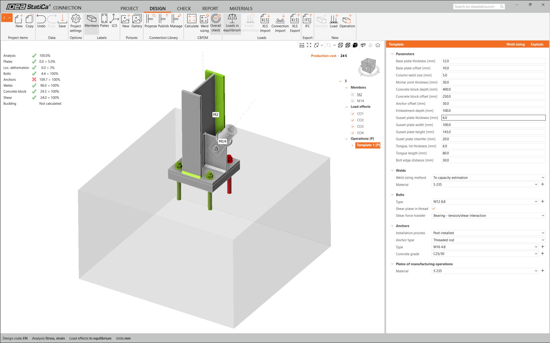
Puede ir a la pestaña Verificar para revisar los resultados y examinar más de cerca los anclajes expandiendo el cálculo con el símbolo '+'. Puede ver que los anclajes están fallando a tracción en el bloque de hormigón.
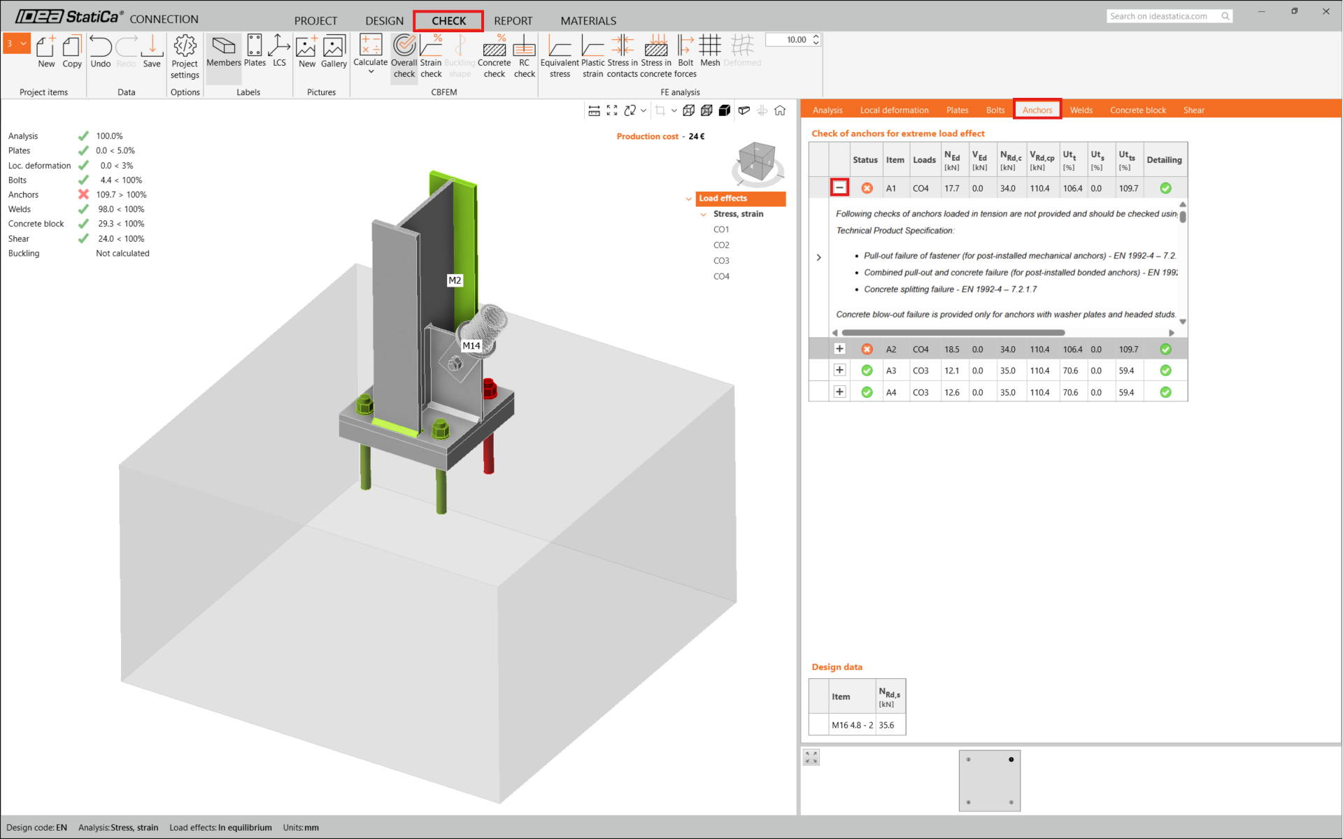
Debemos optimizar el diseño para encontrar la solución válida. Vuelva a la pestaña Diseño , haga clic en la operación y cambie la Longitud de anclaje a 200 mm. Luego ejecute de nuevo el análisis y la verificación normativa.
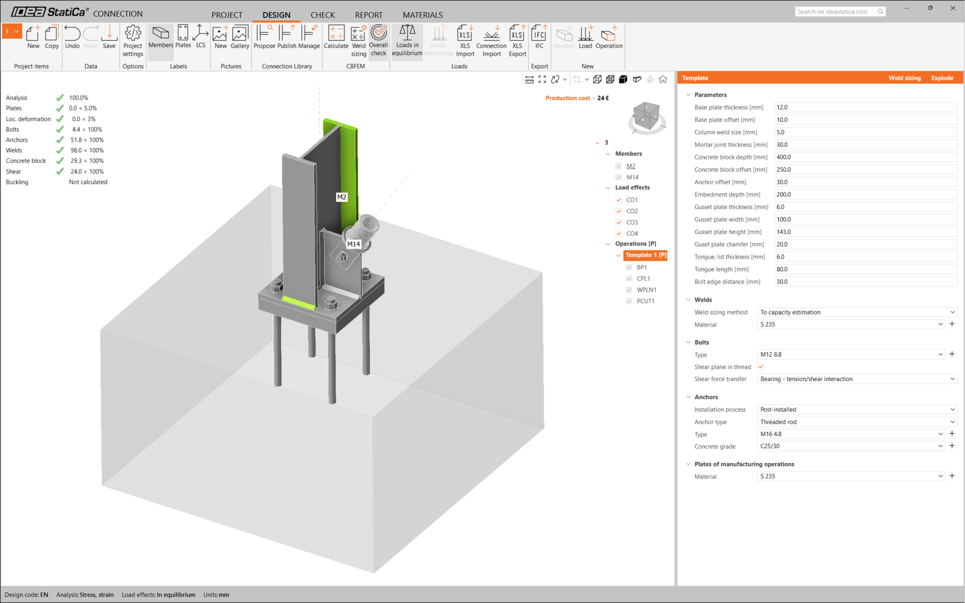
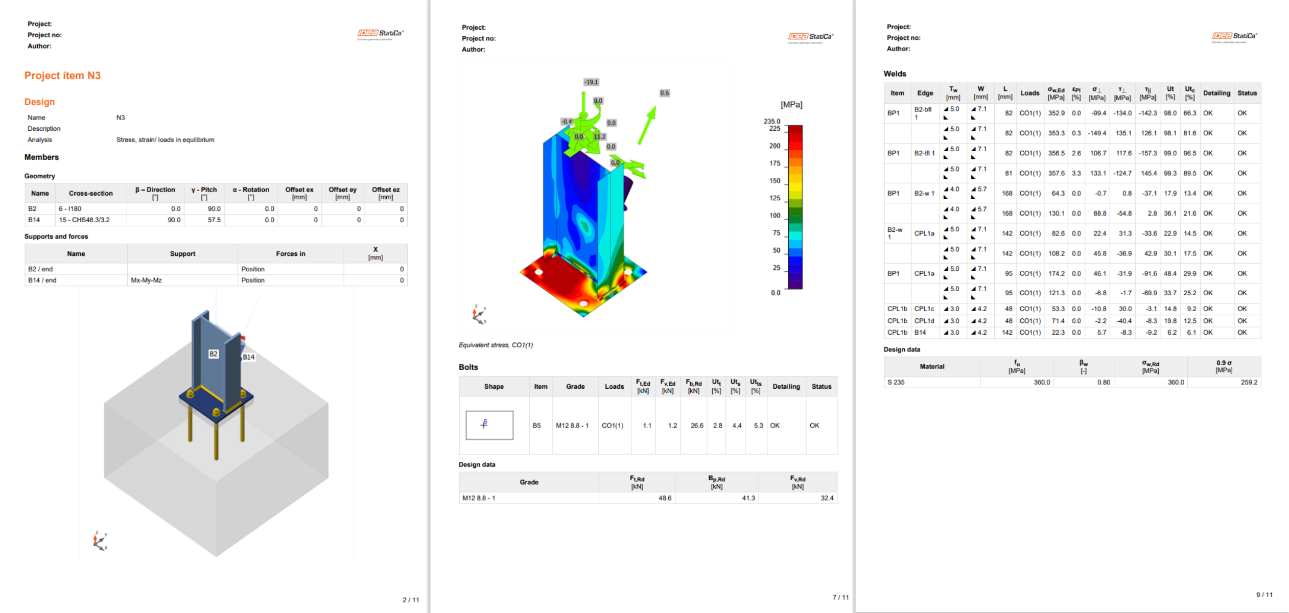
Una vez finalizada la verificación normativa, en la pestaña Informe puede crear el informe con los resultados y diagramas de su modelo de unión.
El informe puede imprimirse o guardarse en varios formatos. Para más información, consulte aquí.
Guarde esta unión y vuelva a la ventana de Checkbot (puede mantener la ventana de Connection abierta).
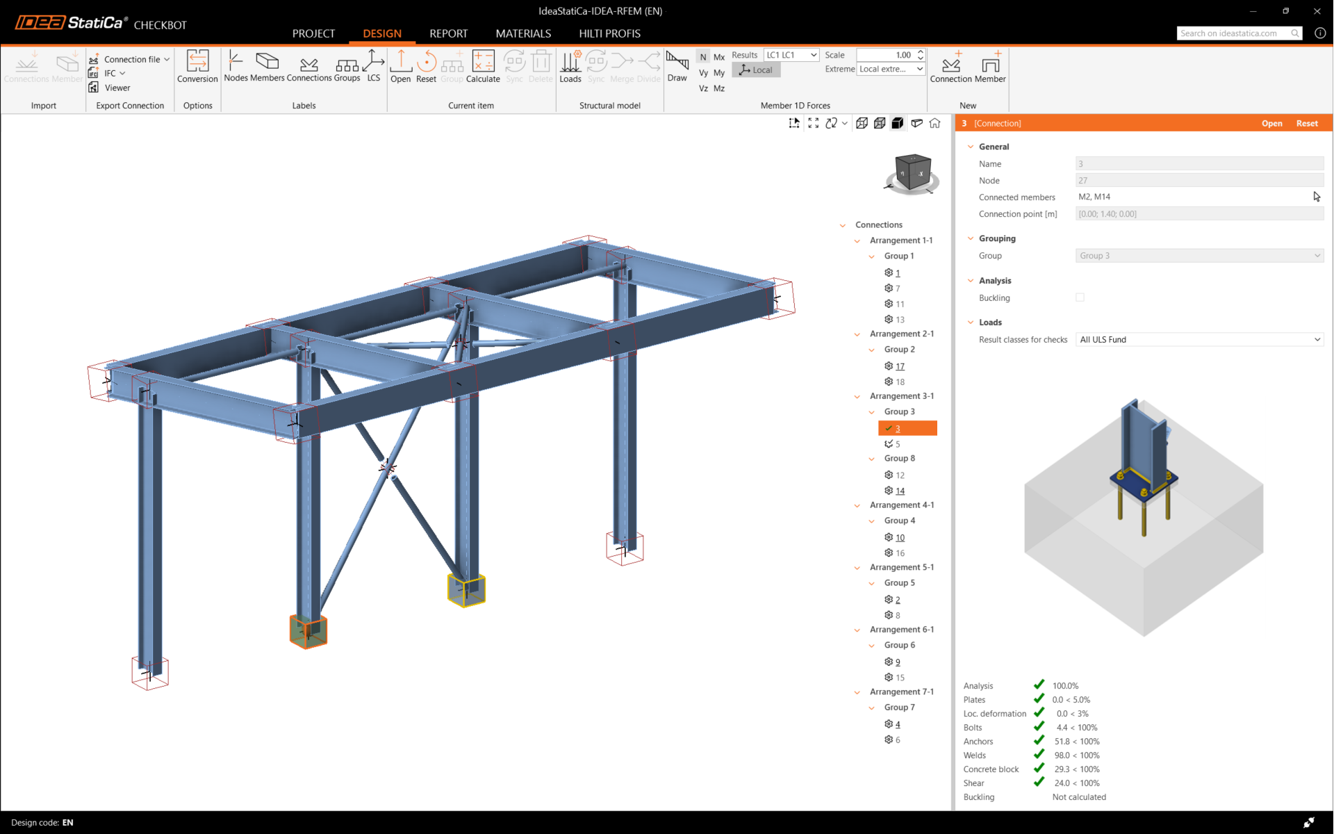
En Checkbot, verá una marca verde junto a la unión y el cuadro del nodo relleno de color verde. Esto significa que la unión ha superado todas las verificaciones normativas. En el panel de Connection, también puede ver una representación de la unión y un resumen de los resultados de la verificación normativa.
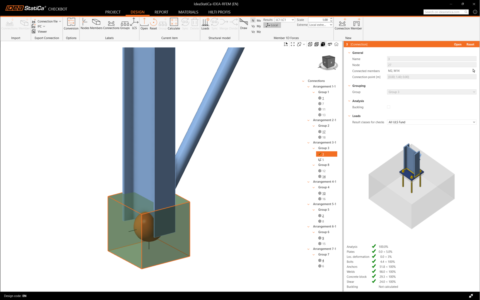
En el ejemplo siguiente, puede ver que solo una unión ha superado la verificación normativa correspondiente, mientras que las uniones restantes aún están por diseñar.
Puede continuar con el diseño de otras uniones, ya sea una por una o utilizando los flujos de trabajo masivos.
Sincronizar uniones
A veces, hay cambios en su modelo de análisis por elementos finitos (FEA), como una sección transversal de elemento diferente o una carga aumentada. Estos pueden sincronizarse entre Checkbot y el modelo FEA.
Hay dos alternativas posibles:
- Sincronizar el Elemento actual (si hay una o más juntas seleccionadas)
- Sincronizar todo el Modelo estructural importado
Para probar esta función, puede cambiar la sección transversal de un elemento en su aplicación FEA. Recuerde volver a analizar el modelo FEA para sincronizar también los resultados actualizados.
En Checkbot, seleccione las uniones diseñadas (puede haber más de una) y desde el panel Elemento actual seleccione Sincronizar.

El proyecto de Checkbot se actualizará. El diseño de la unión previamente finalizado se conserva, pero las verificaciones normativas quedarán invalidadas. Puede ver que la columna ahora está actualizada, coincidiendo con el cambio en el modelo FEA.
Simplemente vuelva a realizar la verificación normativa de las uniones resaltadas seleccionando Calcular desde el panel Elemento actual.
Si las uniones no ofrecen los resultados deseados, puede abrirlas de nuevo para optimizar el diseño (es decir, reforzarlas si no superan la verificación normativa o aligerar si la utilización es demasiado baja).
Los cambios más importantes en el modelo FEA pueden requerir la sincronización de todo el modelo estructural en Checkbot, en lugar de solo el elemento actual.

Tenga en cuenta que los elementos o cargas recién añadidos no pueden sincronizarse, y se debe crear un nuevo proyecto de Checkbot.
Ha vinculado correctamente SCIA Engineer con IDEA StatiCa Connection a través de Checkbot.
Lea más sobre las limitaciones conocidas del enlace BIM de SCIA Engineer.